Page 116 of 518

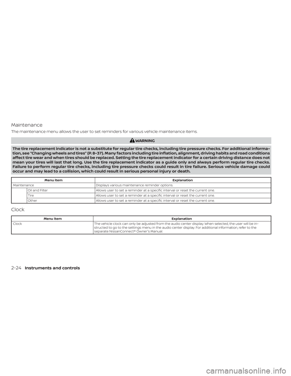
Maintenance
The maintenance menu allows the user to set reminders for various vehicle maintenance items.
WARNING
The tire replacement indicator is not a substitute for regular tire checks, including tire pressure checks. For additional informa-
tion, see “Changing wheels and tires” (P. 8-37). Many factors including tire inflation, alignment, driving habits and road conditions
affect tire wear and when tires should be replaced. Setting the tire replacement indicator for a certain driving distance does not
mean your tires will last that long. Use the tire replacement indicator as a guide only and always perform regular tire checks.
Failure to perform regular tire checks, including tire pressure checks could result in tire failure. Serious vehicle damage could
occur and may lead to a collision, which could result in serious personal injury or death.
Menu item Explanation
Maintenance Displays various maintenance reminder options.
Oil and Filter Allows user to set a reminder at a specific interval or reset the current one.
Tire Allows user to set a reminder at a specific interval or reset the current one.
Other Allows user to set a reminder at a specific interval or reset the current one.
Clock
Menu item Explanation
Clock The vehicle clock can only be adjusted from the audio center display. When selected, the user will be in-
structed to go to the settings menu in the audio center display. For additional information, refer to the
separate NissanConnect® Owner's Manual.
2-24Instruments and controls
Page 130 of 518
NOTE:
The top and bottom few rows of wires on
the rear window are not part of the rear
window defroster system. These wires
make up the antenna for the audio
system.
HEADLIGHT CONTROL SWITCH
Lighting
�1Rotate the switch to theposition,
and the front parking, tail, license plate,
and instrument panel lights will come
on.
�2Rotate the switch to theposition,
and the headlights will come on and all
the other lights remain on.
CAUTION
Use the headlights with the engine run-
ning to avoid discharging the vehicle
battery.
LIC3240
Type A (if so equipped)
LIC3241
Type B (if so equipped)
HEADLIGHT AND TURN SIGNAL
SWITCH
2-38Instruments and controls
Page 147 of 518
1. Type-C USB
2. Type-A USB
There are USB/iPod® charging ports lo-
cated in the rear seat area on the back of
the center console. These ports will charge
compatible devices.
NOTE:
• Only the USB connection port(s) lo-cated below the instrument panel will
allow operation of USB/iPod® devices
through the audio system.
• For best results, it is recommended to use the manufacturer cables, which
are sold separately. A USB Type-A to
USB Type-C adapter (or vice versa) can
also be purchased separately; how-
ever, results may vary.
The extended storage switch is pulled out
when in transit from the factory to the re-
tailer. It is located in the fuse panel to the
lef t of the steering wheel on the instrument
panel. If any electrical equipment does not
operate, ensure the extended storage
switch is pushed fully in place, as shown.
LIC5051
Rear seat area
LIC4599
USB/iPod® CHARGING PORTS EXTENDED STORAGE SWITCH
Instruments and controls2-55
Page 171 of 518

CAUTION
Listed below are conditions or occur-
rences which will damage the Intelli-
gent Key:
• Do not allow the Intelligent Key,
which contains electrical compo-
nents, to come into contact with wa-
ter or salt water. This could affect the
system function.
• Do not drop the Intelligent Key.
• Do not strike the Intelligent Key
sharply against another object.
• Do not change or modif y the Intelli-
gent Key.
• Wetting may damage the Intelligent
Key. If the Intelligent Key gets wet,
immediately wipe until it is com-
pletely dry.
• Do not place the Intelligent Key for an
extended period in an area where
temperatures exceed 140°F (60°C).
• Do not attach the Intelligent Key with
a key holder that contains a magnet.
• Do not place the Intelligent Key near
equipment that produces a magnetic
field, such as a TV, audio equipment
and personal computers. If an Intelligent Key is lost or stolen,
NISSAN recommends erasing the ID
code of that Intelligent Key from the
vehicle. This may prevent the unau-
thorized use of the Intelligent Key to
operate the vehicle. For information
regarding the erasing procedure, it is
recommended that you visit a NISSAN
dealer.
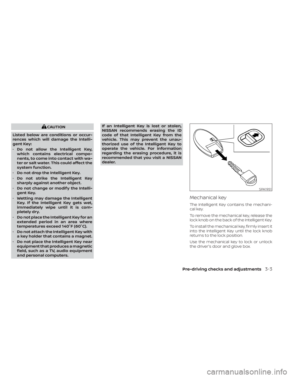
Mechanical key
The Intelligent Key contains the mechani-
cal key.
To remove the mechanical key, release the
lock knob on the back of the Intelligent Key.
To install the mechanical key, firmly insert it
into the Intelligent Key until the lock knob
returns to the lock position.
Use the mechanical key to lock or unlock
the driver's door and glove box.
SPA1951
Pre-driving checks and adjustments3-3
Page 207 of 518

4 Monitor, climate, audio, phone and
voice recognition systems
NissanConnect® Owner’s Manual...............4-2
RearView Monitor (if so equipped) ...............4-3
RearView Monitor system operation ..........4-4
How to read the displayed lines ..............4-4
Difference between predicted and
actual distances .............................4-5
How to park with predicted course
lines ..........................................4-7
Adjusting the screen .........................4-8
How to turn on and off predicted
course lines ..................................4-8
RearView Monitor system limitations .........4-9
System maintenance ....................... 4-10
Intelligent Around View® Monitor (if so
equipped) ....................................... 4-11
Intelligent Around View® Monitor
system operation ........................... 4-12
Difference between predicted and
actual distances ............................ 4-16
How to park with predicted course
lines ......................................... 4-17
How to switch the display ...................4-18Adjusting the screen
........................ 4-19
Intelligent Around View® Monitor
system limitations .......................... 4-20
System maintenance .......................4-22
Moving Object Detection (MOD)
(if so equipped) ................................. 4-23
MOD system operation ......................4-24
Turning MOD on and off .....................4-26
MOD system limitations .....................4-26
System maintenance .......................4-27
Vents .......................................... 4-27
Heater and Air Conditioner (automatic) .........4-29
Automatic operation ........................ 4-30
Manual operation ........................... 4-31
Operating tips ............................... 4-32
Servicing air conditioner ........................4-32
Antenna ........................................ 4-33
Roof Mounted Antenna ......................4-33
Car phone or CB radio .......................... 4-33
iPod®/iPhone® ................................. 4-34
Page 208 of 518
Refer to the digital NissanConnect® Own-
er’s manual using the QR code on this
page, or your printed NissanConnect®
Owner’s manual (if so equipped). This
manual includes the following information:
• NissanConnect® Services (if so equipped)
• Navigation system (if so equipped)
• Audio system
• Apple CarPlay®
• Android Auto™
• Bluetooth® Hands-Free Phone system
• Viewing information
• Other settings• Voice recognition
• General system information
LHA5686
NISSANCONNECT® OWNER’S
MANUAL
4-2Monitor, climate, audio, phone and voice recognition systems
Page 209 of 518
1. CAMERA button
WARNING
• Failure to follow the warnings and in-
structions for proper use of the Rear-
View Monitor system could result in
serious injury or death. •
RearView Monitor is a convenience
feature and is not a substitute for
proper backing. Always turn and look
out the windows and check mirrors
to be sure that it is safe to move be-
fore operating the vehicle. Always
back up slowly. •
The system is designed as an aid to
the driver in showing large station-
ary objects directly behind the ve-
hicle, to help avoid damaging the
vehicle.
LHA5076
REARVIEW MONITOR (if so
equipped)
Monitor, climate, audio, phone and voice recognition systems4-3
Page 210 of 518

•The distance guide line and the ve-
hicle width line should be used as a
reference only when the vehicle is on
a level paved surface. The distance
viewed on the monitor is for refer-
ence only and may be different than
the actual distance between the ve-
hicle and displayed objects.
CAUTION
Do not scratch the camera lens when
cleaning dirt or snow from the front of
the camera.
The RearView Monitor system automati-
cally shows a rear view of the vehicle when
the shif t lever is shif ted into the R (Reverse)
position. While in the R (Reverse), pressing
the CAMERA button will cycle through
guideline options. The radio can still be
heard while the RearView Monitor is active. To display the rear view, the RearView Moni-
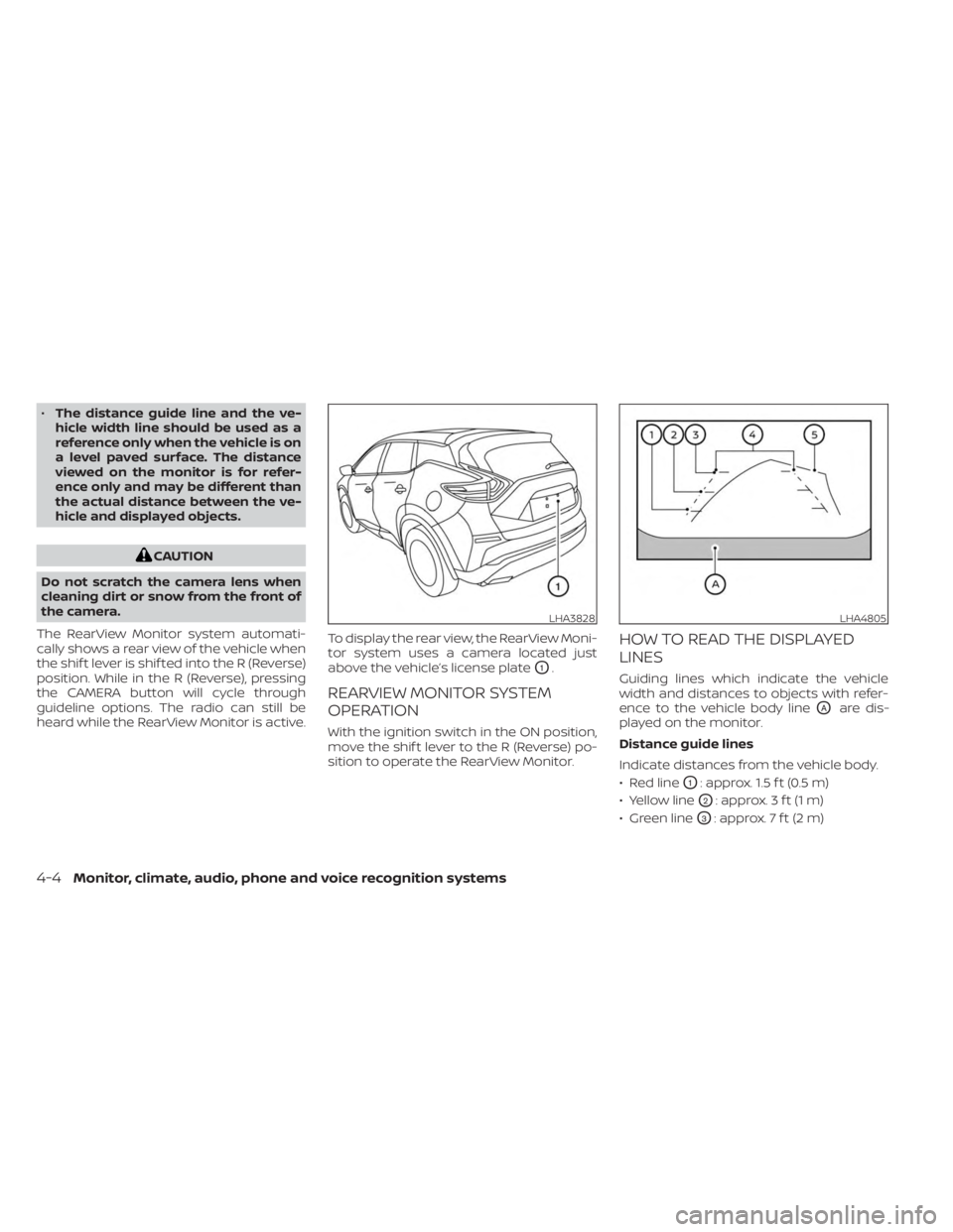
tor system uses a camera located just
above the vehicle’s license plate
O1.
REARVIEW MONITOR SYSTEM
OPERATION
With the ignition switch in the ON position,
move the shif t lever to the R (Reverse) po-
sition to operate the RearView Monitor.
HOW TO READ THE DISPLAYED
LINES
Guiding lines which indicate the vehicle
width and distances to objects with refer-
ence to the vehicle body line
OAare dis-
played on the monitor.
Distance guide lines
Indicate distances from the vehicle body.
• Red line
O1: approx. 1.5 f t (0.5 m)
• Yellow line
O2: approx. 3 f t (1 m)
• Green line
O3: approx. 7 f t (2 m)
LHA3828LHA4805
4-4Monitor, climate, audio, phone and voice recognition systems