2023 NISSAN MURANO coolant
[x] Cancel search: coolantPage 18 of 518
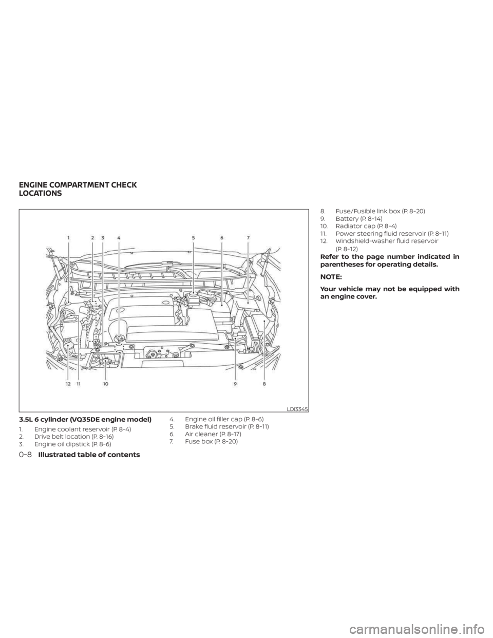
3.5L 6 cylinder (VQ35DE engine model)
1. Engine coolant reservoir (P. 8-4)
2. Drive belt location (P. 8-16)
3. Engine oil dipstick (P. 8-6)4. Engine oil filler cap (P. 8-6)
5. Brake fluid reservoir (P. 8-11)
6. Air cleaner (P. 8-17)
7. Fuse box (P. 8-20)8. Fuse/Fusible link box (P. 8-20)
9. Battery (P. 8-14)
10. Radiator cap (P. 8-4)
11. Power steering fluid reservoir (P. 8-11)
12. Windshield-washer fluid reservoir
(P. 8-12)
Refer to the page number indicated in
parentheses for operating details.
NOTE:
Your vehicle may not be equipped with
an engine cover.
LDI3345
ENGINE COMPARTMENT CHECK
LOCATIONS
0-8Illustrated table of contents
Page 92 of 518
2 Instruments and controls
Instrument panel................................2-2
Meters and gauges .............................2-4
Speedometer and odometer .................2-4
Tachometer ..................................2-6
Engine coolant temperature gauge ..........2-6
Fuel gauge ................................... 2-7
Distance To Empty (DTE) ..................... 2-7
Eco Drive Report (if so equipped) .............2-8
Warning lights, indicator lights and audible
reminders .......................................2-9
Checking lights .............................. 2-10
Warning/Indicator lights (red) ...............2-10
Warning/Indicator lights (yellow) ............2-12
Warning/Indicator lights (other) .............2-17
Audible reminders ........................... 2-17
Vehicle information display .....................2-18
How to use the vehicle information
display ...................................... 2-18
Startup display .............................. 2-19
Settings ..................................... 2-19
Vehicle information display warnings
and indicators ............................... 2-26
Security systems ............................... 2-32
Vehicle security system .....................2-32
NISSAN Vehicle Immobilizer System .........2-34
Wiper and washer switch .......................2-35Switch operation
............................ 2-35
Rear switch operation .......................2-36
Rear window and outside mirror
(if so equipped) defroster switch ...............2-37
Headlight and turn signal switch ...............2-38
Headlight control switch ....................2-38
LED Daytime Running Lights (DRL)
system ...................................... 2-43
Instrument brightness control ..............2-43
Turn signal switch ........................... 2-44
Fog light switch (if so equipped) .............2-44
Horn ........................................... 2-45
Climate controlled seat switches
(if so equipped) ................................. 2-45
Heated seat switches (if so equipped) ..........2-47
Heated rear seat switches (if so equipped) .....2-48
Heated steering wheel switch (if so equipped) . . 2-49
Dynamic
driver assistance switch ..............2-50
Vehicle Dynamic Control (VDC) OFF switch .....2-50
Emergency call (SOS) button (if so equipped) . . . 2-51 Emergency support ......................... 2-51
Rear Door Alert ................................. 2-53
Power outlets .................................. 2-54
12v outlets .................................. 2-54
USB/iPod® charging ports ......................2-55
Page 96 of 518
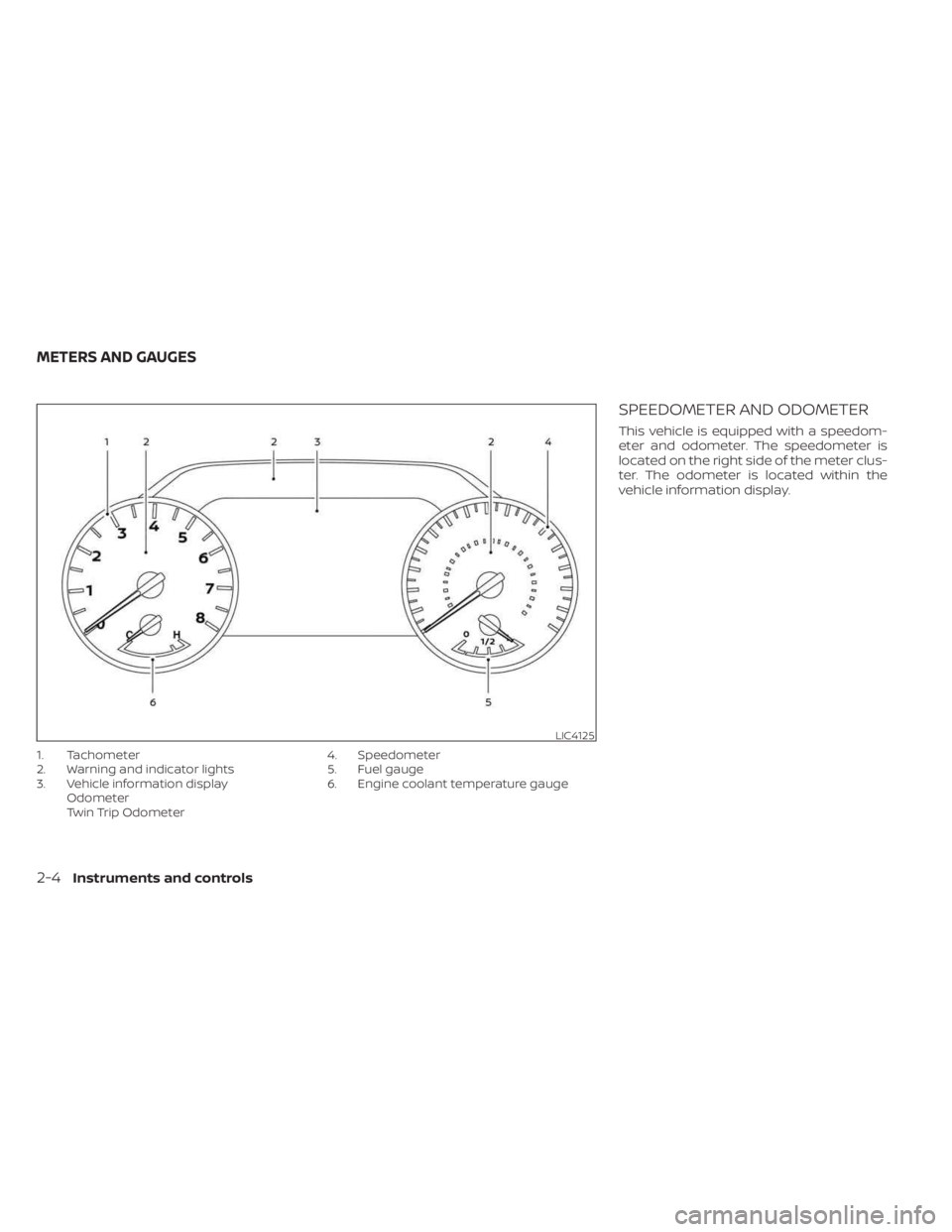
1. Tachometer
2. Warning and indicator lights
3. Vehicle information displayOdometer
Twin Trip Odometer 4. Speedometer
5. Fuel gauge
6. Engine coolant temperature gauge
SPEEDOMETER AND ODOMETER
This vehicle is equipped with a speedom-
eter and odometer. The speedometer is
located on the right side of the meter clus-
ter. The odometer is located within the
vehicle information display.
LIC4125
METERS AND GAUGES
2-4Instruments and controls
Page 98 of 518
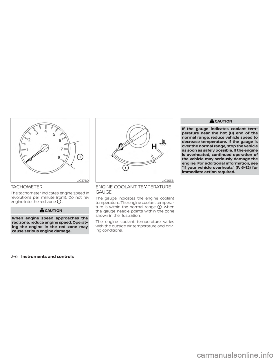
TACHOMETER
The tachometer indicates engine speed in
revolutions per minute (rpm). Do not rev
engine into the red zone
O1.
CAUTION
When engine speed approaches the
red zone, reduce engine speed. Operat-
ing the engine in the red zone may
cause serious engine damage.
ENGINE COOLANT TEMPERATURE
GAUGE
The gauge indicates the engine coolant
temperature. The engine coolant tempera-
ture is within the normal range
O1when
the gauge needle points within the zone
shown in the illustration.
The engine coolant temperature varies
with the outside air temperature and driv-
ing conditions.
CAUTION
If the gauge indicates coolant tem-
perature near the hot (H) end of the
normal range, reduce vehicle speed to
decrease temperature. If the gauge is
over the normal range, stop the vehicle
as soon as safely possible. If the engine
is overheated, continued operation of
the vehicle may seriously damage the
engine. For additional information, see
“If your vehicle overheats” (P. 6-12) for
immediate action required.
LIC3780LIC3538
2-6Instruments and controls
Page 238 of 518
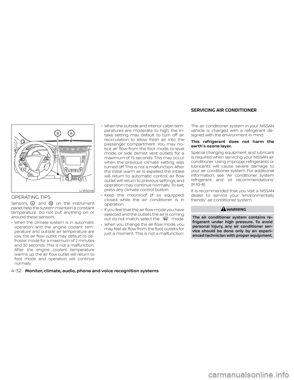
OPERATING TIPS
Sensors,OAandOBon the instrument
panel, help the system maintain a constant
temperature. Do not put anything on or
around these sensors.
•
When the climate system is in automatic
operation and the engine coolant tem-
perature and outside air temperature are
low, the air flow outlet may default to de-
froster mode for a maximum of 2 minutes
and 30 seconds. This is not a malfunction.
Af ter the engine coolant temperature
warms up, the air flow outlet will return to
foot mode and operation will continue
normally.
• When the outside and interior cabin tem- peratures are moderate to high, the in-
take setting may default to turn off air
recirculation to allow fresh air into the
passenger compartment. You may no-
tice air flow from the foot mode, bi-level
mode, or side demist vent outlets for a
maximum of 15 seconds. This may occur
when the previous climate setting was
turned off. This is not a malfunction. Af ter
the initial warm air is expelled, the intake
will return to automatic control, air flow
outlet will return to previous settings, and
operation may continue normally. To exit,
press any climate control button.
• Keep the moonroof (if so equipped) closed while the air conditioner is in
operation.
• If you feel that the air flow mode you have selected and the outlets the air is coming
out do not match, select the
mode.
• When you change the air flow mode, you may feel air flow from the foot outlets for
just a moment. This is not a malfunction. The air conditioner system in your NISSAN
vehicle is charged with a refrigerant de-
signed with the environment in mind.
This refrigerant does not harm the
earth's ozone layer.
Special charging equipment and lubricant
is required when servicing your NISSAN air
conditioner. Using improper refrigerants or
lubricants will cause severe damage to
your air conditioner system. For additional
information, see “Air conditioner system
refrigerant and oil recommendations”
(P. 10-8).
It is recommended that you visit a NISSAN
dealer to service your “environmentally
friendly” air conditioner system.
WARNING
The air conditioner system contains re-
frigerant under high pressure. To avoid
personal injury, any air conditioner ser-
vice should be done only by an experi-
enced technician with proper equipment.
LHA5046
SERVICING AIR CONDITIONER
4-32Monitor, climate, audio, phone and voice recognition systems
Page 243 of 518
System maintenance......................5-110
Intelligent Driver Alertness (I-DA) ...............5-112
Intelligent Driver Alertness system
operation .................................. 5-112
How to enable/disable the Intelligent
Driver Alertness (I-DA) system ..............5-113
Intelligent Driver Alertness (I-DA)
system limitations ......................... 5-114
Break-in schedule ............................. 5-115
Fuel efficient driving tips .......................5-115
Increasing fuel economy ......................5-116
All-Wheel Drive (AWD) (if so equipped) ...........5-117
Parking/parking on hills .......................5-119
Power steering ................................ 5-120
Brake system ................................. 5-121
Brake precautions .......................... 5-121
Anti-lock Braking System (ABS) .............5-121
Brake Assist ................................ 5-123Vehicle Dynamic Control (VDC) system
........5-123
Rise-up and build-up ....................... 5-124
Brake force distribution ....................5-125
Hill start assist system ........................5-126
Front and rear sonar system (if so equipped) . . 5-126 System operation .......................... 5-127
How to enable/disable the front and
rear sonar system .......................... 5-129
Sonar limitations ........................... 5-130
System temporarily unavailable ............5-130
System maintenance ......................5-130
Cold weather driving .......................... 5-131
Freeing a frozen door lock ..................5-131
Antifreeze .................................. 5-131
Battery..................................... 5-131
Draining of coolant water ..................5-131
Tire equipment ............................. 5-131
Special winter equipment ..................5-132
Driving on snow or ice ......................5-132
Page 258 of 518
REMOTE ENGINE START (if so
equipped)
Vehicles started with the Remote Engine
Start require the ignition switch to be
placed in the ON position before the shif t
lever can be moved from the P (Park) posi-
tion. To place the ignition switch in the ON
position, follow these steps:
1. Make sure that the Intelligent Key is onyou.
2. Apply the brake.
3. Push the ignition switch once to the ON position.
For additional information, see “NISSAN In-
telligent Key®” (P. 3-2).
ENGINE PROTECTION MODE
The engine has an engine protection mode
to reduce the chance of damage if the
coolant temperature becomes too high
(for example, when climbing steep grades
in high temperatures with heavy loads,
such as when towing a trailer). When the
engine temperature reaches a certain
level:
• The engine coolant temperature gauge will move toward the H position.
• Engine power may be reduced.
• The air conditioning cooling function may be automatically turned off for a short
time (the blower will continue to operate).
Engine power and, under some conditions,
vehicle speed will decrease. Vehicle speed
can be controlled with the accelerator
pedal, but the vehicle may not accelerate at
the desired speed. The transmission will
downshif t or upshif t as it reaches pre-
scribed shif t points. You can also shif t
manually.
As driving conditions change and engine
coolant temperature is reduced, vehicle
speed can be increased using the accel-
erator pedal, and the air conditioning cool-
ing function will automatically be turned
back on. The Malfunction Indicator Light (MIL) may
also come on if the engine coolant tem-
perature is not reduced or the air condi-
tioning cooling function does not turn back
on. If
only it remains on, you do not need to
have your vehicle towed, but have it in-
spected soon. It is recommended that you
visit a NISSAN dealer for this service. For
additional information, see “Malfunction In-
dicator Light (MIL)” (P. 2-14).
WARNING
Overheating can result in reduced en-
gine power and vehicle speed. The re-
duced speed may be lower than other
traffic, which could increase the chance
of a collision. Be especially careful
when driving. If the vehicle cannot
maintain a safe driving speed, pull to
the side of the road in a safe area. Allow
the engine to cool and return to normal
operation. For additional information,
see “If your vehicle overheats” (P. 6-12).
DRIVING THE VEHICLE
5-18Starting and driving
Page 371 of 518
The sonar sensors may be blocked by tem-
porary ambient conditions such as splash-
ing water, mist or fog.
The blocked condition may also be caused
by objects such as ice, frost or dirt ob-
structing the sonar sensors.
Check for and remove objects obstructing
the area around the sonar sensors.
Do not attach stickers (including transpar-
ent material), install accessories or apply
additional paint near the sonar sensors.
Do not strike or damage the area around
the sonar sensors. It is recommended that
you visit a NISSAN dealer if the area around
the sonar sensors is damaged due to a
collision.FREEING A FROZEN DOOR LOCK
To prevent a door lock from freezing, apply
de-icer through the key hole. If the lock
becomes frozen, heat the key before in-
serting it into the key hole, or use the
NISSAN Intelligent Key®.
ANTIFREEZE
In the winter when it is anticipated that the
temperature will drop below 32°F (0°C),
check the antifreeze to assure proper win-
ter protection. For additional information,
see “Engine cooling system” (P. 8-4).
BATTERY
If the battery is not fully charged during
extremely cold weather conditions, the
battery fluid may freeze and damage the
battery. To maintain maximum efficiency,
the battery should be checked regularly.
For additional information, see “Battery”
(P. 8-14).
DRAINING OF COOLANT WATER
If the vehicle is to be lef t outside without
antifreeze, drain the cooling system, includ-
ing the engine block. Refill before operating
the vehicle. For additional information, see
“Changing engine coolant” (P. 8-5).
TIRE EQUIPMENT
1. SUMMER tires have a tread designed toprovide superior performance on dry
pavement. However, the performance of
these tires will be substantially reduced
in snowy and icy conditions. If you oper-
ate your vehicle on snowy or icy roads,
NISSAN recommends the use of MUD &
SNOW or ALL SEASON TIRES on all four
wheels. It is recommended that you visit
a NISSAN dealer for the tire type, size,
speed rating and availability information.
2. For additional traction on icy roads, studded tires may be used. However,
some U.S. states and Canadian prov-
inces prohibit their use. Check local,
state and provincial laws before install-
ing studded tires.
Skid and traction capabilities of studded
snow tires on wet or dry surfaces may be
poorer than that of non-studded snow
tires.
3. Tire chains may be used. For additional information, see “Tire chains” (P. 8-36).
COLD WEATHER DRIVING
Starting and driving5-131