2023 NISSAN MURANO ignition
[x] Cancel search: ignitionPage 413 of 518

WARNING
Be sure the engine and ignition switch
are off and that the parking brake is
engaged securely.
CAUTION
Be sure to use the correct socket to re-
move the spark plugs. An incorrect
socket can damage the spark plugs.
If replacement is required, it is recom-
mended that you visit a NISSAN dealer for
this service. The air cleaner filter should not be cleaned
and reused. Replace it according to the
maintenance log shown in the "Mainte-
nance and schedules" section of this
manual.
To remove the air cleaner filter:
1. Unlatch the retaining clips
OA.
2. Move the air cleaner cover upwards.
3. Remove the air cleaner filter. Wipe the inside of the air cleaner filter housing
and the cover with a damp cloth, then
replace air cleaner filter.
NOTE:
Af ter installing a new air cleaner filter,
make sure the air cleaner cover is seated
in the housing and latch the clips.
WARNING
• Operating the engine with the air
cleaner removed can cause you or
others to be burned. The air cleaner
not only cleans the air, it stops the
flame if the engine backfires. If it isn't
there, and the engine backfires, you
could be burned. Do not drive with
the air cleaner removed, and be care-
ful when working on the engine with
the air cleaner removed.
• Never pour fuel into the throttle body
or attempt to start the engine with
the air cleaner removed. Doing so
could result in serious injury.
LDI2553
AIR CLEANER
Do-it-yourself8-17
Page 417 of 518
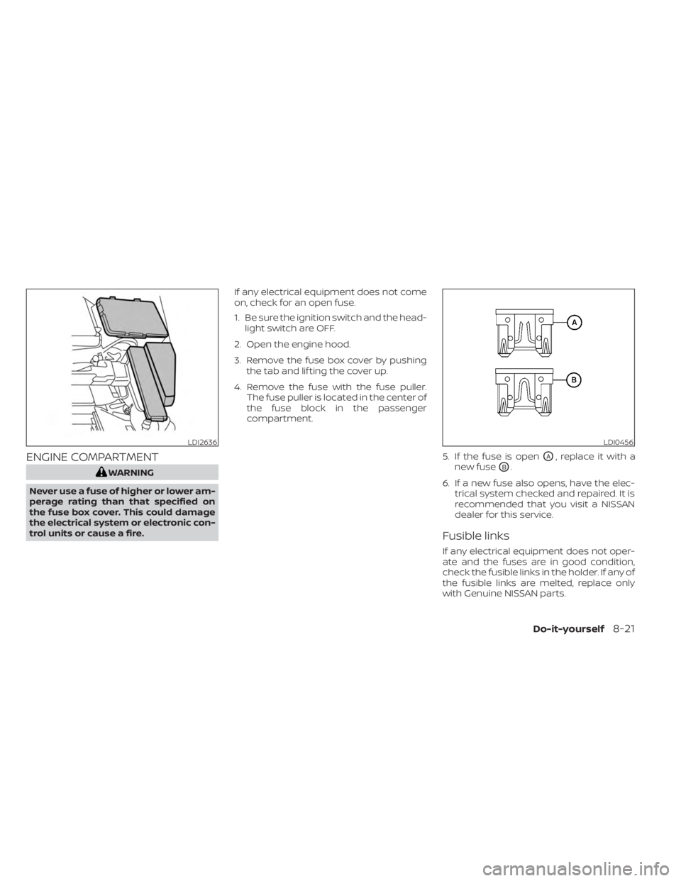
ENGINE COMPARTMENT
WARNING
Never use a fuse of higher or lower am-
perage rating than that specified on
the fuse box cover. This could damage
the electrical system or electronic con-
trol units or cause a fire. If any electrical equipment does not come
on, check for an open fuse.
1. Be sure the ignition switch and the head-
light switch are OFF.
2. Open the engine hood.
3. Remove the fuse box cover by pushing the tab and lif ting the cover up.
4. Remove the fuse with the fuse puller. The fuse puller is located in the center of
the fuse block in the passenger
compartment.
5. If the fuse is open
OA, replace it with a
new fuse
OB.
6. If a new fuse also opens, have the elec- trical system checked and repaired. It is
recommended that you visit a NISSAN
dealer for this service.
Fusible links
If any electrical equipment does not oper-
ate and the fuses are in good condition,
check the fusible links in the holder. If any of
the fusible links are melted, replace only
with Genuine NISSAN parts.
LDI2636LDI0456
Do-it-yourself8-21
Page 418 of 518
For checking and replacing the fusible links,
it is recommended that you visit a NISSAN
dealer for this service.
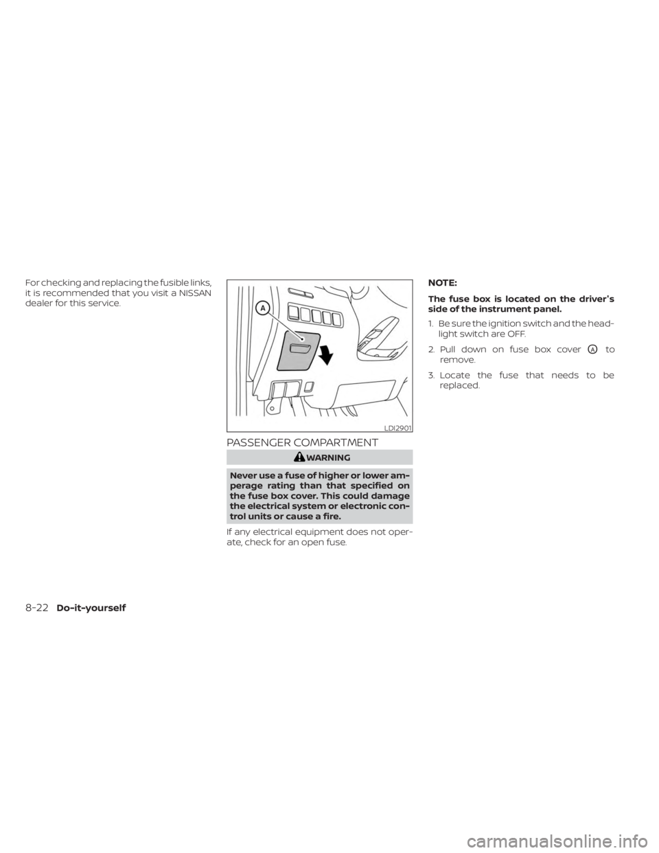
PASSENGER COMPARTMENT
WARNING
Never use a fuse of higher or lower am-
perage rating than that specified on
the fuse box cover. This could damage
the electrical system or electronic con-
trol units or cause a fire.
If any electrical equipment does not oper-
ate, check for an open fuse.
NOTE:
The fuse box is located on the driver's
side of the instrument panel.
1. Be sure the ignition switch and the head- light switch are OFF.
2. Pull down on fuse box cover
OAto
remove.
3. Locate the fuse that needs to be replaced.
LDI2901
8-22Do-it-yourself
Page 474 of 518
Af termarket fuel additives
NISSAN does not recommend the use of
any af termarket fuel additives (for ex-
ample, fuel injector cleaner, octane
booster, intake valve deposit removers,
etc.) which are sold commercially. Many of
these additives intended for gum, varnish
or deposit removal may contain active sol-
vents or similar ingredients that can be
harmful to the fuel system and engine.
Octane rating tips
Using unleaded gasoline with an octane
rating lower than recommended can
cause persistent, heavy “spark knock.”
(“Spark knock” is a metallic rapping
noise.) If severe, this can lead to engine
damage. If you detect a persistent heavy
spark knock even when using gasoline
of the stated octane rating, or if you hear
steady spark knock while holding a
steady speed on level roads, it is recom-
mended that you have a NISSAN dealer
correct the condition. Failure to correct
the condition is misuse of the vehicle, for
which NISSAN is not responsible.Incorrect ignition timing may result in
spark knock, af ter-run and/or overheating,
which may cause excessive fuel consump-
tion or engine damage. If any of the above
symptoms are encountered, have your ve-
hicle checked. It is recommended that you
visit a NISSAN dealer for servicing.
However, now and then you may notice
light spark knock for a short time while
accelerating or driving up hills. This is not
a cause for concern, because you get the
greatest fuel benefit when there is light
spark knock for a short time under heavy
engine load.
10-6Technical and consumer information
Page 477 of 518
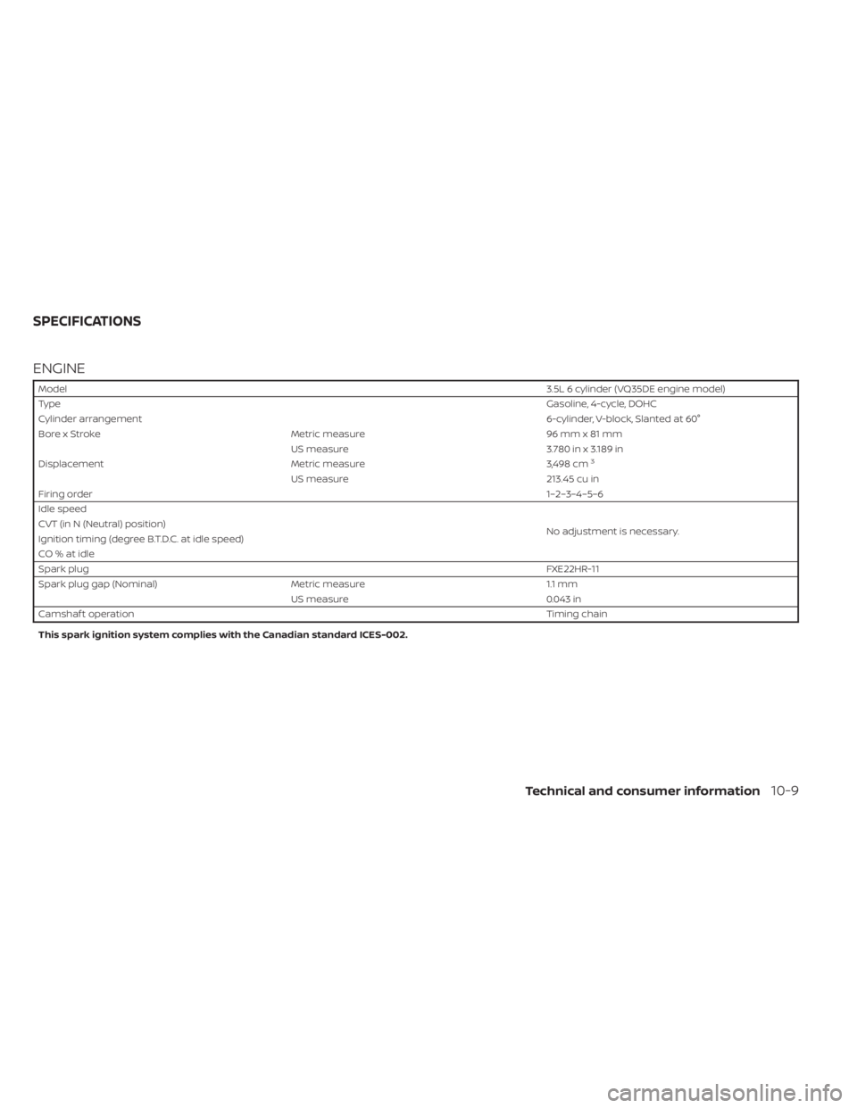
ENGINE
Model3.5L 6 cylinder (VQ35DE engine model)
Type Gasoline, 4-cycle, DOHC
Cylinder arrangement 6-cylinder, V-block, Slanted at 60°
Bore x Stroke Metric measure 96 mm x 81 mm
US measure 3.780 in x 3.189 in
Displacement Metric measure 3,498 cm
3
US measure213.45 cu in
Firing order 1–2–3–4–5–6
Idle speed
No adjustment is necessary.
CVT (in N (Neutral) position)
Ignition timing (degree B.T.D.C. at idle speed)
CO%atidle
Spark plug
FXE22HR-11
Spark plug gap (Nominal) Metric measure 1.1 mm
US measure 0.043 in
Camshaf t operation Timing chain
This spark ignition system complies with the Canadian standard ICES-002.
SPECIFICATIONS
Technical and consumer information10-9
Page 493 of 518
Weight carrying hitches
A weight carrying or “dead weight” ball
mount is one that is designed to carry the
whole amount of tongue weight and gross
weight directly on the ball mount and on
the receiver.
Weight distribution hitch
This type of hitch is also called a “load-
leveling” or “equalizing” hitch. A set of bars
attach to the ball mount and to the trailer
to distribute the tongue weight (hitch
weight) of your trailer. Many vehicles can't
carry the full tongue weight of a given
trailer, and need some of the tongue
weight transferred through the frame and
pushing down on the front wheels. This
gives stability to the tow vehicle.
A weight-distributing hitch system (Class
IV) is recommended if you plan to tow trail-
ers with a maximum weight over 5,000 lbs.
(2,268 kg). Check with the trailer and towing
equipment manufacturers to determine if
they recommend the use of a weight-
distributing hitch system.
NOTE:
A weight-distributing hitch system may
affect the operation of trailer surge
brakes. If you are considering use of a
weight-distributing hitch system with a
surge brake-equipped trailer, check with
the surge brake, hitch or trailer manufac-
turer to determine if and how this can be
done.
Follow the instructions provided by the
manufacturer for installing and using the
weight-distributing hitch system.
General set-up instructions are as follows:
1. Park unloaded vehicle on a level surface.With the ignition switch in the ON posi-
tion and the doors closed, allow the ve-
hicle to stand for several minutes so that
it can level.
2. Measure the height of a reference point on the front and rear bumpers at the
center of the vehicle.
3. Attach the trailer to the vehicle and ad- just the hitch equalizers so that the front
bumper height is within0-.5inches (0 –
13 mm) of the reference height mea-
sured in step 2. The rear bumper should
be no higher than the reference height
measured in step 2.
WARNING
Properly adjust the weight distributing
hitch so the rear of the bumper is no
higher than the measured reference
height when the trailer is attached. If
the rear bumper is higher than the
measured reference height when
loaded, the vehicle may handle unpre-
dictably which could cause a loss of ve-
hicle control and cause serious per-
sonal injury or property damage.
Sway control device
Sudden maneuvers, wind gusts, and buf-
feting caused by other vehicles can affect
trailer handling. Sway control devices may
be used to help control these affects. If you
choose to use one, contact a reputable
trailer hitch supplier to make sure the sway
control device will work with the vehicle,
hitch, trailer and the trailer's brake system.
Follow the instructions provided by the
manufacturer for installing and using the
sway control device.
Technical and consumer information10-25
Page 500 of 518
WARNING
A vehicle equipped with All -Wheel
Drive (AWD) should never be tested us-
ing a two wheel dynamometer (such as
the dynamometers used by some
states for emissions testing), or similar
equipment. Make sure you inform the
test facility personnel that your vehicle
is equipped with AWD before it is placed
on a dynamometer. Using the wrong
test equipment may result in drivetrain
damage or unexpected vehicle move-
ment which could result in serious ve-
hicle damage or personal injury.
Due to legal requirements in some states
and Canadian Provinces, your vehicle may
be required to be in what is called the
“ready condition” for an Inspection/
Maintenance (I/M) test of the emission
control system.
The vehicle is set to the “ready condition”
when it is driven through certain driving
patterns. Usually, the ready condition can
be obtained by ordinary usage of the
vehicle. If a powertrain system component is re-
paired or the battery is disconnected, the
vehicle may be reset to a “not ready” condi-
tion. Before taking the I/M test, check the
vehicle's inspection/maintenance test
readiness condition. Place the ignition
switch in the ON position without starting
the engine. If the Malfunction Indicator
Light (MIL) comes on steady for 20 seconds
and then blinks for 10 seconds , the I/M test
condition is “not ready”. If the MIL does not
blink af ter 20 seconds, the I/M test condi-
tion is “ready”. It is recommended that you
visit a NISSAN dealer to set the “ready con-
dition” or to prepare the vehicle for testing.
This vehicle is equipped with an Event Data
Recorder (EDR). The main purpose of an
EDR is to record, in certain crash or near
crash-like situations, such as an air bag
deployment or hitting a road obstacle, data
that will assist in understanding how a ve-
hicle's systems performed. The EDR is de-
signed to record data related to vehicle dy-
namics and safety systems for a short
period of time, typically 30 seconds or less.
The EDR in this vehicle is designed to re-
cord such data as:
• How various systems in your vehicle were
operating;
• Whether or not the driver and passenger safety belts were buckled/fastened;
• How far (if at all) the driver was depress- ing the accelerator and/or brake pedal;
and,
• How fast the vehicle was traveling.
• Sounds are not recorded.
READINESS FOR INSPECTION/
MAINTENANCE (I/M) TEST EVENT DATA RECORDERS (EDR)
10-32Technical and consumer information
Page 505 of 518
Front and rear sonar system.........5-126
Front power seat adjustment ..........1-4
Frontseats....................... .1-2
Front-door pocket .................2-56
Fuelefficientdrivingtips.............5 -115
Fuel gauge ........................2-7
Fuel-filler door ....................3-28
Fuel.............................10-2 Capacities and recommended
fuel/lubricants ..................10-2
Fuel economy ..................5 -116
Fuel gauge ......................2-7
Fueloctanerating................10-6
Fuel recommendation ............10-4
Fuel-filler cap ...................3-29
Fuel-filler door lock opener lever .....3-28
Fuel-filler lid ....................3-29
Loose fuel cap warning ............2-27
Fuses ...........................8-20
Fusiblelinks ......................8-21
G
Garage door opener, HomeLink® Universal
Transceiver .......................2-71
Gascap.........................3-29
Gauge ...........................2-6
Engine coolant temperature gauge . . .2-6
Fuel gauge ......................2-7
Odometer ......................2-5
Speedometer .................2-4,2-5
Tachometer .....................2-6
Trip odometer ...................2-5 General maintenance
................9-2
Glovebox........................2-59
H
Hazard warning flasher switch .........6-2
Headrestraints.................... .1-9
Headlight and turn signal switch .......2-38
Headlightcontrolswitch.............2-38
Headlights.......................8-25
Heatedmirrors................... .3-36
Heatedrearseats..................2-48
Heatedseats.....................2-45
Heated steering wheel ..............2-49
Heater and air conditioner (automatic) . .4-29
Heater..........................4-29 Heater and air conditioner (automatic)
(if so equipped) ..................4-29
Heater and air conditioner controls. . .4-30
Heater operation .................4-31
Hill start assist system ..............5-126
HomeLink® Universal Transceiver.......2-71
Hood ............................3-21
Hook ...........................2-62
Luggage hook ..................2-62
Horn............................2-45
I
Ignition switch .....................5-13
Push-button ignition switch ........5-13
Immobilizer system ................2-34
Important vehicle information label . . . .10-12In-cabinmicrofilter.................8-18
Increasing fuel economy
............5-116
Indicator lights and audible reminders
(See warning/indicator lights and audible
reminders) ...................... .2-10
Indicator.........................5-15 NISSAN Intelligent Key® battery discharge
indicator.......................5-15
Inside automatic anti-glare mirror .....3-34
Instrument brightness control ........2-43
Instrument panel dimmer switch ......2-43
Instrument panel ...................0-6
Intelligent Around View® Monitor .......4-11
Intelligent Cruise Control ............5-59
Intelligent Drive Alertness (I-DA) .......5-112
Intelligent Forward Collision Warning
(I-FCW)..........................5-99
Intelligent Key system ................3-8
Key operating range ...............3-8
Key operation ....................3-9
Mechanical key ...................3-3
Remote keyless entry operation .....3-12
Troubleshooting guide ............3-16
Warning signals ..................3-16
Intelligent Lane Intervention ..........5-33
Interiorlight..................... .2-69
ISOFIX child restraints ...............1-28
J
Jumpstarting.....................6-10
11-3