2023 NISSAN MURANO light
[x] Cancel search: lightPage 187 of 518
REMOTE STARTING THE VEHICLE
To use the Remote Engine Start feature to
start the engine perform the following:
1. Aim the Intelligent Key at the vehicle.
2. Press the
button to lock all doors.
3. Within 5 seconds press and hold the
button until the turn signal lights
flash and the tail lamps turn on. If the
vehicle is not within view press and hold
the
button for at least 2 seconds.
The following events will occur when the
engine starts:
• The parking lights will turn on and remain on as long as the engine is running.
• The doors will be locked and the climate control system may come on.
• The engine will continue to run for 10 min- utes. Repeat the steps to extend the time
for an additional 10 minutes. For addi-
tional information, see “Extending engine
run time” (P. 3-19).
Press and hold the brake then push the
push-button ignition switch to the ON po-
sition before driving. For additional infor-
mation, see “Driving the vehicle” (P. 5-18).
EXTENDING ENGINE RUN TIME
The Remote Engine Start feature can be
extended one time by performing the
steps listed in “Remote starting the vehicle”
(P. 3-19). Run time will be calculated as
follows:
• The first 10–minute run time will start when the Remote Engine Start function is
performed.
• The second 10 minutes will start immedi- ately when the Remote Engine Start
function is performed again. For example,
if the engine has been running for 5 min-
utes, and 10 minutes are added, the en-
gine will run for a total of 15 minutes.
• Extending engine run time will bring you to the two Remote Engine Start limit.
A maximum of two Remote Engine Starts,
or a single start with an extension, are al-
lowed between ignition cycles.
The ignition switch must be cycled to the
ON position and then back to the OFF po-
sition before the Remote Engine Start pro-
cedure can be used again.
CANCELING A REMOTE ENGINE
START
To cancel a Remote Engine Start, perform
one of the following:
• Aim the Intelligent Key at the vehicle and press
until the parking lights turn off.
• Turn on the hazard indicator flashers.
• Cycle the ignition switch on and then off.
• The extended engine run time has expired.
• The first 10–minute timer has expired.
• The engine hood has been opened.
• The vehicle is shif ted out of P (Park) position.
• The alarm sounds due to illegal entry into the vehicle.
• The ignition switch is pushed without an Intelligent Key in the vehicle.
• The ignition switch is pushed with an In- telligent Key in the vehicle but the brake
pedal is not depressed.
Pre-driving checks and adjustments3-19
Page 188 of 518
CONDITIONS THE REMOTE ENGINE
START WILL NOT WORK
The Remote Engine Start will not operate if
any of the following conditions are present:
• The ignition switch is placed in the ONposition.
• The hood is not securely closed.
• The hazard indicator lights are on.
• The engine is still running. The engine must be completely stopped. Wait at
least 6 seconds if the engine goes from
running to off. This is not applicable when
extending engine run time.
• The
button is not pressed and held
for at least 2 seconds.
• The
button is not pressed and held
within 5 seconds of pressing the lock
button.
• The brake is pressed.
• The doors are not closed and locked.
• The lif tgate is open.
• The Key System Fault warning light re- mains solid is in the vehicle information
display.
• The alarm sounds due to illegal entry into the vehicle. • Two Remote Engine Starts, or a single
Remote Engine Start with an extension,
have already been used.
• The vehicle is not in P (Park).
• There is a detected registered key already inside of the vehicle.
• The Remote Engine Start function has been switched to the OFF position in Ve-
hicle Settings of the vehicle information
display. For additional information, see
“Vehicle information display” (P. 2-18).
The Remote Engine Start may display a
warning or indicator in the vehicle informa-
tion display. For additional information, see
“Vehicle information display” (P. 2-18).
3-20Pre-driving checks and adjustments
Page 189 of 518
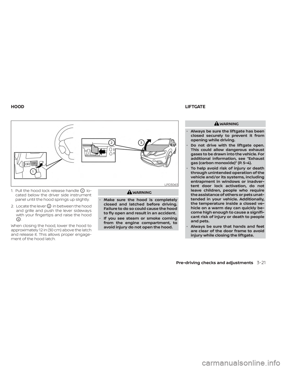
1. Pull the hood lock release handleO1lo-
cated below the driver side instrument
panel until the hood springs up slightly.
2. Locate the lever
O2in between the hood
and grille and push the lever sideways
with your fingertips and raise the hood
O3.
When closing the hood, lower the hood to
approximately 12 in (30 cm) above the latch
and release it. This allows proper engage-
ment of the hood latch.
WARNING
• Make sure the hood is completely
closed and latched before driving.
Failure to do so could cause the hood
to fly open and result in an accident.
• If you see steam or smoke coming
from the engine compartment, to
avoid injury do not open the hood.
WARNING
• Always be sure the lif tgate has been
closed securely to prevent it from
opening while driving.
•
Do not drive with the lif tgate open.
This could allow dangerous exhaust
gases to be drawn into the vehicle. For
additional information, see “Exhaust
gas (carbon monoxide)” (P. 5-4).
• To help avoid risk of injury or death
through unintended operation of the
vehicle and/or its systems, including
entrapment in windows or inadver-
tent door lock activation, do not
leave children, people who require
the assistance of others or pets unat-
tended in your vehicle. Additionally,
the temperature inside a closed ve-
hicle on a warm day can quickly be-
come high enough to cause a signifi-
cant risk of injury or death to people
and pets.
• Always be sure that hands and feet
are clear of the door frame to avoid
injury while closing the lif tgate.
LPD3063
HOOD LIFTGATE
Pre-driving checks and adjustments3-21
Page 197 of 518
FUEL-FILLER CAP
WARNING
• Gasoline is extremely flammable and
highly explosive under certain condi-
tions. You could be burned or seri-
ously injured if it is misused or mis-
handled. Always stop the engine and
do not smoke or allow open flames
or sparks near the vehicle when
refueling.
• Do not attempt to top off the fuel
tank af ter the fuel pump nozzle
shuts off automatically. Continued
refueling may cause fuel overflow,
resulting in fuel spray and possibly a
fire.
• Use only an original equipment type
fuel-filler cap as a replacement. It has
a built-in safety valve needed for
proper operation of the fuel system
and emission control system. An in-
correct cap can result in a serious
malfunction and possible injury. It
could also cause the
Malfunc-
tion Indicator Light (MIL) to come on.
• Never pour fuel into the throttle body
to attempt to start your vehicle. •
Do not fill a portable fuel container in
the vehicle or trailer. Static electricity
can cause an explosion of flammable
liquid, vapor or gas in any vehicle or
trailer. To reduce the risk of serious
injury or death when filling portable
fuel containers:
– Always place the container on the
ground when filling.
– Do not use electronic devices
when filling.
– Keep the pump nozzle in contact
with the container while you are
filling it.
– Use only approved portable fuel
containers for flammable liquid.
CAUTION
• Do not use a fuel containing more
than 15% ethanol in your vehicle. For
additional information, see “Fuel rec-
ommendation” (P. 10-4). •
The Loose Fuel Cap warning mes-
sage will appear if the fuel-filler cap
is not properly tightened. It may take
a few driving trips for the message to
be displayed. Failure to tighten the
fuel-filler cap properly af ter the
Loose Fuel Cap warning message
appears may cause the
Mal-
function Indicator Light (MIL) to
illuminate.
• Failure to tighten the fuel-filler cap
properly may cause the
Mal-
function Indicator Light (MIL) to illu-
minate. If the
light illuminates
because the fuel-filler cap is loose or
missing, tighten or install the cap and
continue to drive the vehicle. The
light should turn off af ter a few
driving trips. If thelight does not
turn off af ter a few driving trips, have
the vehicle inspected. It is recom-
mended that you visit a NISSAN
dealer for this service.
•
For additional information, see “Mal-
function Indicator Light (MIL)” (P. 2-14).
• If fuel is spilled on the vehicle body,
flush it away with water to avoid
paint damage.
Pre-driving checks and adjustments3-29
Page 202 of 518
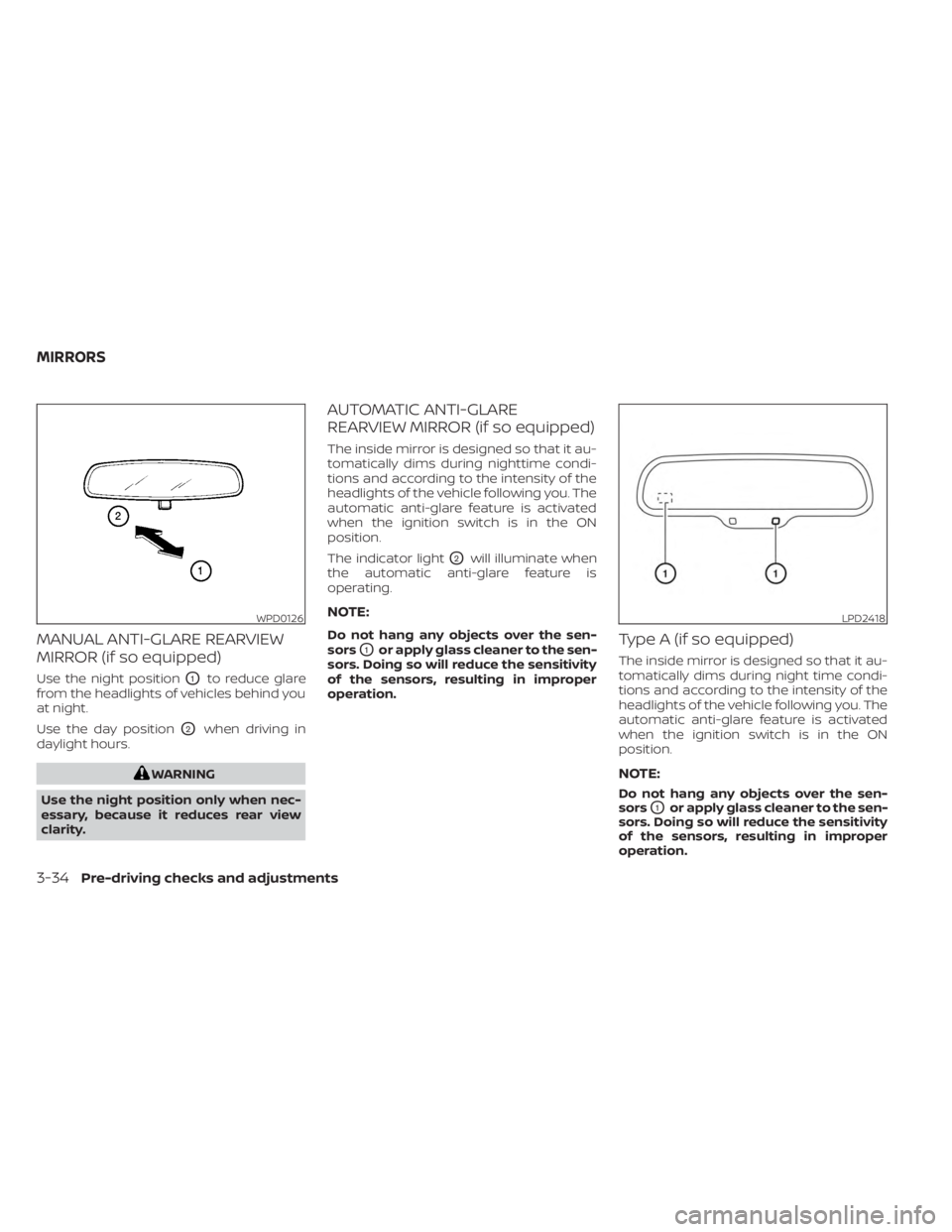
MANUAL ANTI-GLARE REARVIEW
MIRROR (if so equipped)
Use the night positionO1to reduce glare
from the headlights of vehicles behind you
at night.
Use the day position
O2when driving in
daylight hours.
WARNING
Use the night position only when nec-
essary, because it reduces rear view
clarity.
AUTOMATIC ANTI-GLARE
REARVIEW MIRROR (if so equipped)
The inside mirror is designed so that it au-
tomatically dims during nighttime condi-
tions and according to the intensity of the
headlights of the vehicle following you. The
automatic anti-glare feature is activated
when the ignition switch is in the ON
position.
The indicator light
O2will illuminate when
the automatic anti-glare feature is
operating.
NOTE:
Do not hang any objects over the sen-
sors
O1or apply glass cleaner to the sen-
sors. Doing so will reduce the sensitivity
of the sensors, resulting in improper
operation.Type A (if so equipped)
The inside mirror is designed so that it au-
tomatically dims during night time condi-
tions and according to the intensity of the
headlights of the vehicle following you. The
automatic anti-glare feature is activated
when the ignition switch is in the ON
position.
NOTE:
Do not hang any objects over the sen-
sors
O1or apply glass cleaner to the sen-
sors. Doing so will reduce the sensitivity
of the sensors, resulting in improper
operation.
WPD0126LPD2418
MIRRORS
3-34Pre-driving checks and adjustments
Page 203 of 518
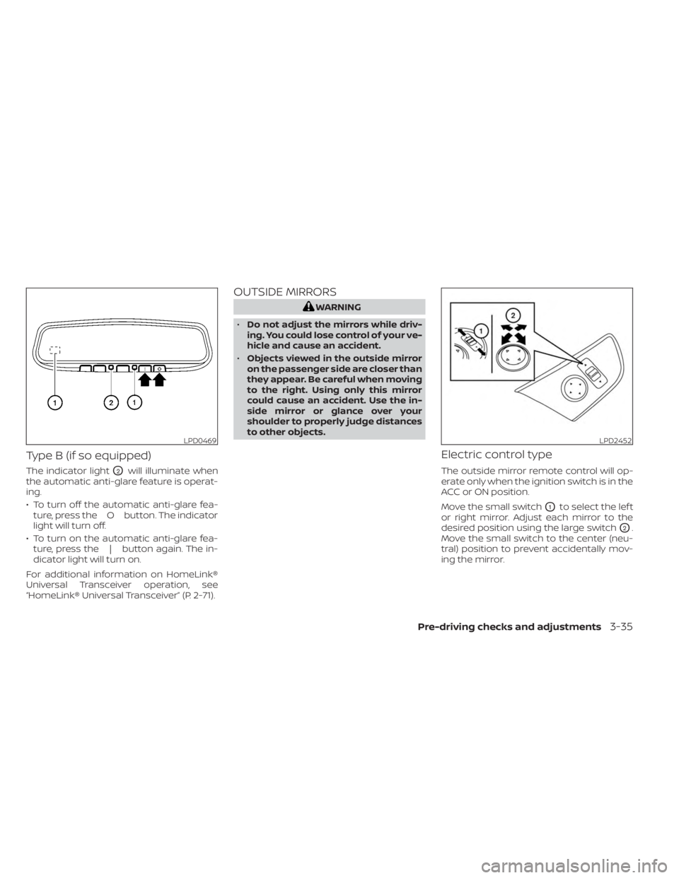
Type B (if so equipped)
The indicator lightO2will illuminate when
the automatic anti-glare feature is operat-
ing.
• To turn off the automatic anti-glare fea- ture, press the O button. The indicator
light will turn off.
• To turn on the automatic anti-glare fea- ture, press the | button again. The in-
dicator light will turn on.
For additional information on HomeLink®
Universal Transceiver operation, see
“HomeLink® Universal Transceiver” (P. 2-71).
OUTSIDE MIRRORS
WARNING
• Do not adjust the mirrors while driv-
ing. You could lose control of your ve-
hicle and cause an accident.
• Objects viewed in the outside mirror
on the passenger side are closer than
they appear. Be careful when moving
to the right. Using only this mirror
could cause an accident. Use the in-
side mirror or glance over your
shoulder to properly judge distances
to other objects.
Electric control type
The outside mirror remote control will op-
erate only when the ignition switch is in the
ACC or ON position.
Move the small switch
O1to select the lef t
or right mirror. Adjust each mirror to the
desired position using the large switch
O2.
Move the small switch to the center (neu-
tral) position to prevent accidentally mov-
ing the mirror.
LPD0469LPD2452
Pre-driving checks and adjustments3-35
Page 206 of 518
2. Push the SET switch and, within 5 sec-onds, push the memory switch (1 or 2).
The indicator light for the pushed memory
switch will come on and stay on for ap-
proximately 5 seconds. The chime will
sound when the memory is stored.
NOTE:
If a new memory position is stored in the
same memory switch, the previous
memory position will be overwritten by
the new stored position.
Recalling switch memory
positions
To recall the manually stored positions,
push the memory switch (1 or 2). The driv-
er’s seat and automatic steering wheel
(if so equipped) will move to the positions
stored to those buttons.
ENTRY/EXIT FUNCTION (if so
equipped)
This system is designed so that the driver's
seat and steering column will automati-
cally move when the shif t lever is in the P
(Park) position. This allows the driver to
easily get in and out of the driver’s seat. The driver’s seat will slide backward and
the steering wheel will move up when the
ignition is switched to OFF and the driver’s
door is open.
The driver’s seat and steering wheel will
return to the previous position when the
ignition switch is switched to ON.
The entry/exit function can be enabled or
disabled through the “Vehicle Settings” in
the vehicle information display by perform-
ing the following:
• Switch the Exit Seat Slide from ON to OFF.
• Switch the Exit Steering Up from ON to
OFF.
Restarting the entry/exit function
If the battery cable is disconnected or if the
fuse opens, the stored memory positions
may be lost and some of the functions will
be restricted.
1. Drive the vehicle over 25 mph (40 km/h).
OR
2. Open and close the driver's door more than two times with the ignition switch
in the OFF position.
The entry/exit function should now work
properly.
SYSTEM OPERATION
The memory seat system will not work or
will stop operating under the following
conditions:
• When the vehicle speed is above 4 mph (7 km/h).
• When any of the memory switches are pushed while the memory seat is
operating.
• When the switch for the driver’s seat and steering wheel is pushed while the
memory seat is operating.
• When the seat has already been moved to the memorized position.
• When no seat position is stored in the memory switch.
• When the shif t position is moved from P (Park) to any other position.
3-38Pre-driving checks and adjustments
Page 215 of 518
REARVIEW MONITOR SYSTEM
LIMITATIONS
WARNING
Listed below are the system limitations
for RearView Monitor. Failure to oper-
ate the vehicle in accordance with
these system limitations could result in
serious injury or death.
• The system cannot completely elimi-
nate blind spots and may not show
every object.
• Underneath the bumper and the cor-
ner areas of the bumper cannot be
viewed on the RearView Monitor be-
cause of its monitoring range limita-
tion. The system will not show small
objects below the bumper, and may
not show objects close to the bum-
per or on the ground.
• Objects viewed in the RearView
Monitor differ from actual distance
because a wide-angle lens is used.
• Objects in the RearView Monitor will
appear visually opposite compared
to when viewed in the rearview and
outside mirrors. •
Use the displayed lines as a refer-
ence. The lines are highly affected by
the number of occupants, fuel level,
vehicle position, road conditions and
road grade.
• Make sure that the lif tgate is securely
closed when backing up.
• Do not put anything on the rearview
camera. The rearview camera is in-
stalled above the license plate.
• When washing the vehicle with high
pressure water, be sure not to spray it
around the camera. Otherwise, water
may enter the camera unit causing
water condensation on the lens, a
malfunction, fire or an electric shock.
• Do not strike the camera. It is a preci-
sion instrument. Otherwise, it may
malfunction or cause damage result-
ing in a fire or an electric shock. The following are operating limitations and
do not represent a system malfunction:
• When the temperature is extremely high
or low, the screen may not clearly display
objects.
• When strong light directly shines on the camera, objects may not be displayed
clearly.
• Vertical lines may be seen in objects on the screen. This is due to strong reflected
light from the bumper.
• The screen may flicker under fluorescent light.
• The colors of objects on the RearView Monitor may differ somewhat from the
actual color of objects.
• Objects on the monitor may not be clear in a dark environment.
• There may be a delay when switching between views.
• If dirt, rain or snow accumulate on the camera, the RearView Monitor may not
display objects clearly. Clean the camera.
• Do not use wax on the camera lens. Wipe off any wax with a clean cloth dampened
with a diluted mild cleaning agent, then
wipe with a dry cloth.
Monitor, climate, audio, phone and voice recognition systems4-9