2023 NISSAN KICKS torque
[x] Cancel search: torquePage 158 of 558
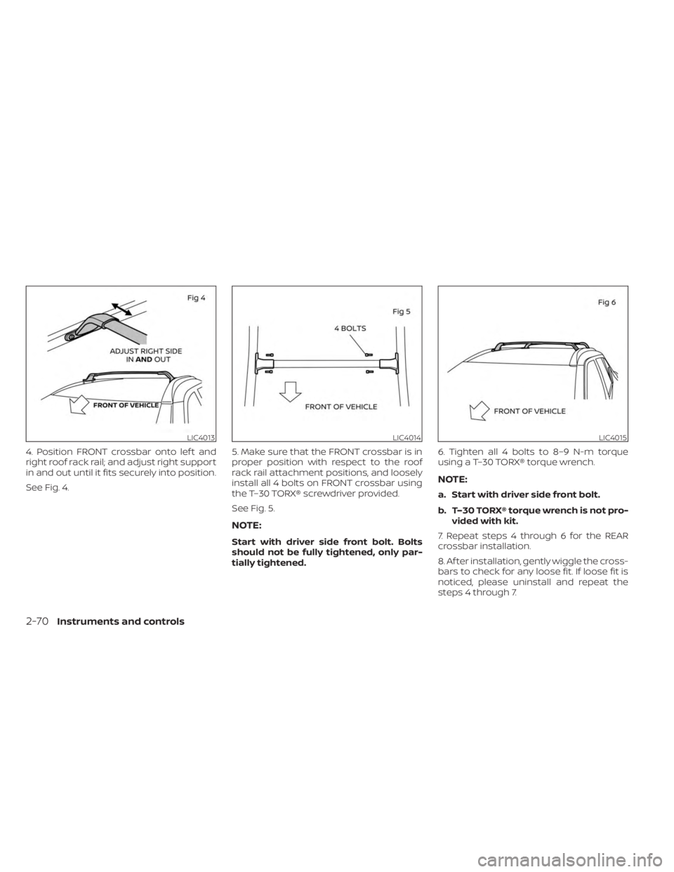
4. Position FRONT crossbar onto lef t and
right roof rack rail; and adjust right support
in and out until it fits securely into position.
See Fig. 4.5. Make sure that the FRONT crossbar is in
proper position with respect to the roof
rack rail attachment positions, and loosely
install all 4 bolts on FRONT crossbar using
the T–30 TORX® screwdriver provided.
See Fig. 5.
NOTE:
Start with driver side front bolt. Bolts
should not be fully tightened, only par-
tially tightened.6. Tighten all 4 bolts to 8–9 N-m torque
using a T–30 TORX® torque wrench.
NOTE:
a. Start with driver side front bolt.
b. T–30 TORX® torque wrench is not pro-
vided with kit.
7. Repeat steps 4 through 6 for the REAR
crossbar installation.
8. Af ter installation, gently wiggle the cross-
bars to check for any loose fit. If loose fit is
noticed, please uninstall and repeat the
steps 4 through 7.
LIC4013LIC4014LIC4015
2-70Instruments and controls
Page 416 of 558
Even if the I–TC is turned OFF, some func-
tions will remain on to assist the driver (for
example, avoidance scenes).
INTELLIGENT ENGINE BRAKE (I-EB)
The I-EB function adds subtle deceleration
by controlling the Continuously Variable
Transmission gear ratio, depending on the
cornering condition calculated from driv-
er's steering input and plural sensors. This
benefit is for easier traceability and less
workload of adjusting speed with braking
at corners.
If the chassis control warning message ap-
pears in the vehicle information display, it
may indicate that the I-EB is not function-
ing properly. Have the system checked by a
NISSAN dealer as soon as possible. For ad-
ditional information, see “Vehicle informa-
tion display” (P. 2-24).
The I-EB also adds subtle deceleration with
gear ratio control according to driver’s
brake pedal operation.
The I-EB can be set to ON (enabled) or OFF
(disabled) through the vehicle information
display “Chassis Control” page. For addi-
tional information, see “Vehicle information
display” (P. 2-24).When the I-EB is operated at corners and
the Chassis Control mode is selected in the
vehicle information display, the I-EB graph-
ics are shown in the vehicle information
display. For additional information, see “Ve-
hicle information display” (P. 2-24).
WARNING
The I-EB may not be effective depend-
ing on driving conditions. Always drive
carefully and attentively.
When the I-EB is operating, the needle of
the tachometer will rise up and you may
hear an engine noise. This is normal and
indicates that the I-EB is operating
properly.
ACTIVE RIDE CONTROL (ARC)
This system senses upper body motion
(based on wheel speed information) and
controls engine torque and four wheel
brake pressure. This will enhance ride com-
fort in effort to restrain uncomfortable up-
per body movement when passing over
undulated road surfaces. When the Vehicle
Dynamic Control (VDC) system is turned off,
the ARC is also turned off. When the ARC is operated and the Chassis
Control mode is selected in the vehicle in-
formation display, the ARC graphics are
shown in the vehicle information display.
For additional information, see “Vehicle in-
formation display” (P. 2-24).
When the ARC is operating, you may hear
noise and sense slight deceleration. This is
normal and indicates that the ARC is oper-
ating properly.
If the chassis control warning message ap-
pears in the vehicle information display, it
may indicate that the ARC is not function-
ing properly. Have the system checked by a
NISSAN dealer as soon as possible. For ad-
ditional information, see “Vehicle informa-
tion display” (P. 2-24).
5-138Starting and driving
Page 435 of 558
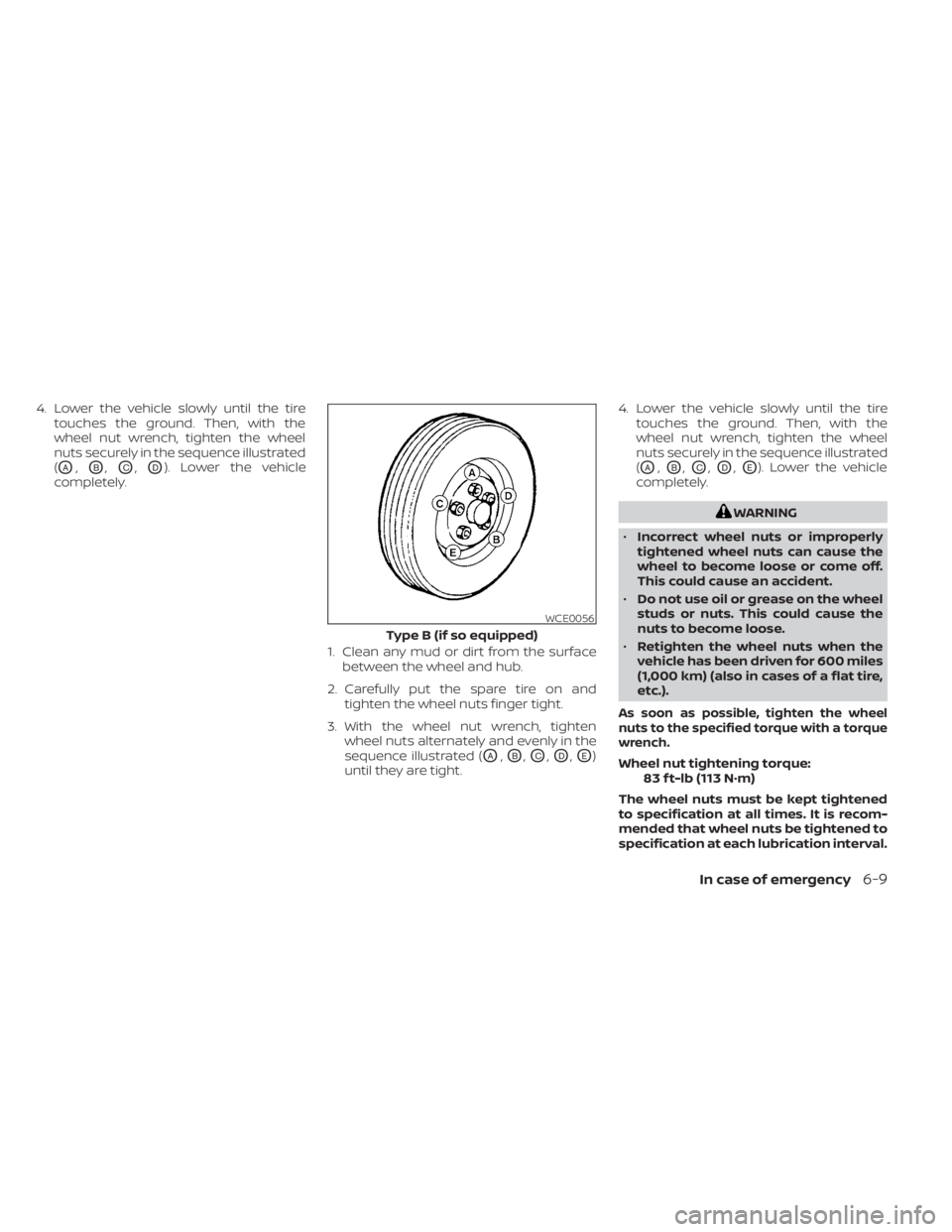
4. Lower the vehicle slowly until the tiretouches the ground. Then, with the
wheel nut wrench, tighten the wheel
nuts securely in the sequence illustrated
(
OA,OB,OC,OD). Lower the vehicle
completely.
1. Clean any mud or dirt from the surfacebetween the wheel and hub.
2. Carefully put the spare tire on and tighten the wheel nuts finger tight.
3. With the wheel nut wrench, tighten wheel nuts alternately and evenly in the
sequence illustrated (
OA,OB,OC,OD,OE)
until they are tight. 4. Lower the vehicle slowly until the tire
touches the ground. Then, with the
wheel nut wrench, tighten the wheel
nuts securely in the sequence illustrated
(
OA,OB,OC,OD,OE). Lower the vehicle
completely.
WARNING
• Incorrect wheel nuts or improperly
tightened wheel nuts can cause the
wheel to become loose or come off.
This could cause an accident.
• Do not use oil or grease on the wheel
studs or nuts. This could cause the
nuts to become loose.
• Retighten the wheel nuts when the
vehicle has been driven for 600 miles
(1,000 km) (also in cases of a flat tire,
etc.).
As soon as possible, tighten the wheel
nuts to the specified torque with a torque
wrench.
Wheel nut tightening torque: 83 f t-lb (113 N·m)
The wheel nuts must be kept tightened
to specification at all times. It is recom-
mended that wheel nuts be tightened to
specification at each lubrication interval.
WCE0056
Type B (if so equipped)
In case of emergency6-9
Page 458 of 558
WARNING
• Prolonged and repeated contact
with used engine oil may cause skin
cancer.
• Try to avoid direct skin contact with
used oil. If skin contact is made, wash
thoroughly with soap or hand
cleaner as soon as possible.
• Keep used engine oil out of reach of
children.
4.
Loosen the oil filter with an oil filter
wrench by turning it counterclockwise.
Remove the oil filter by turning it by hand.
5. Wipe the engine oil filter mounting sur- face with a clean rag.
CAUTION
Be sure to remove any old gasket ma-
terial remaining on the sealing surface
of the engine. Failure to do so could
lead to an oil leak and engine damage.
• The dipstick must be inserted in
place to prevent oil spillage from the
dipstick hole when filling the engine
with oil. 6. Coat the gasket on the new filter with
clean engine oil.
7. Screw in the oil filter clockwise until a slight resistance is felt, then tighten addi-
tionally more than 2/3 turn.
Oil filter tightening torque: 11 to 15 f t-lb (14.7 to 20.6 N·m)
8. Clean and re-install the drain plug with a new washer. Securely tighten the drain
plug with a wrench. Do not use exces-
sive force.
Drain plug tightening torque: 22 to 29 f t-lb (29.4 to 39.2 N·m)
9. Refill the engine with the recommended oil through the oil filler opening, and in-
stall the oil filler cap securely.
For additional information about drain and
refill capacity, see “Recommended fluids/
lubricants and capacities” (P. 10-2). The
drain and refill capacity depends on the oil
temperature and drain time. Use these
specifications for reference only. Always
use the dipstick to determine the proper
amount of oil in the engine. 10. Start the engine and check for leakage
around the drain plug and the oil filter.
Correct as required. Turn the engine off
and wait more than 15 minutes. Check
the oil level with the dipstick. Add en-
gine oil if necessary.
Af ter the operation
1. Lower the vehicle carefully to the ground.
2. Reset oil and oil filter maintenance re-minder (if so equipped). For additional
information, see “Vehicle information
display” (P. 2-24).
• Dispose of waste oil and filter properly.
• Check your local regulations.
8-8Do-it-yourself
Page 487 of 558
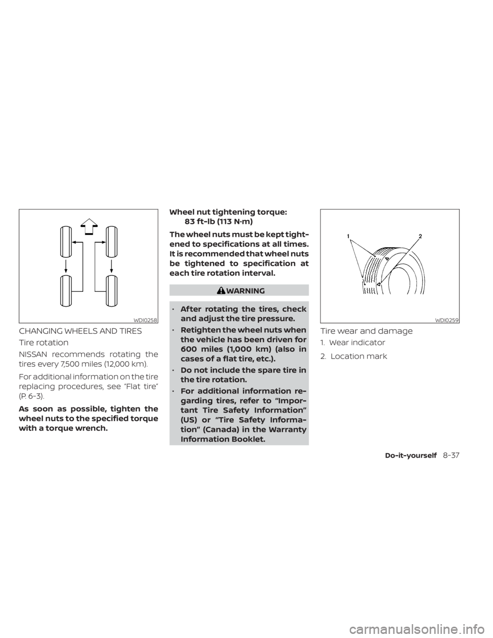
CHANGING WHEELS AND TIRES
Tire rotation
NISSAN recommends rotating the
tires every 7,500 miles (12,000 km).
For additional information on the tire
replacing procedures, see “Flat tire”
(P. 6-3).
As soon as possible, tighten the
wheel nuts to the specified torque
with a torque wrench.Wheel nut tightening torque:
83 f t-lb (113 N·m)
The wheel nuts must be kept tight-
ened to specifications at all times.
It is recommended that wheel nuts
be tightened to specification at
each tire rotation interval.
WARNING
• Af ter rotating the tires, check
and adjust the tire pressure.
• Retighten the wheel nuts when
the vehicle has been driven for
600 miles (1,000 km) (also in
cases of a flat tire, etc.).
• Do not include the spare tire in
the tire rotation.
• For additional information re-
garding tires, refer to “Impor-
tant Tire Safety Information”
(US) or “Tire Safety Informa-
tion” (Canada) in the Warranty
Information Booklet.
Tire wear and damage
1. Wear indicator
2. Location mark
WDI0258WDI0259
Do-it-yourself8-37