2023 NISSAN KICKS weight
[x] Cancel search: weightPage 96 of 558
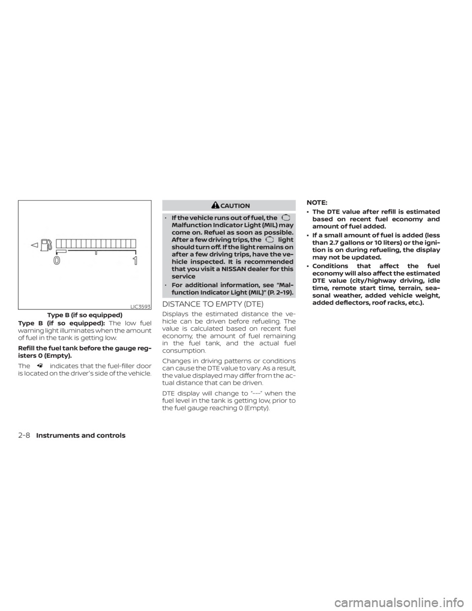
Type B (if so equipped):The low fuel
warning light illuminates when the amount
of fuel in the tank is getting low.
Refill the fuel tank before the gauge reg-
isters 0 (Empty).
The
indicates that the fuel-filler door
is located on the driver's side of the vehicle.
CAUTION
• If the vehicle runs out of fuel, the
Malfunction Indicator Light (MIL) may
come on. Refuel as soon as possible.
Af ter a few driving trips, the
light
should turn off. If the light remains on
af ter a few driving trips, have the ve-
hicle inspected. It is recommended
that you visit a NISSAN dealer for this
service
•
For additional information, see “Mal-
function Indicator Light (MIL)” (P. 2-19).
DISTANCE TO EMPTY (DTE)
Displays the estimated distance the ve-
hicle can be driven before refueling. The
value is calculated based on recent fuel
economy, the amount of fuel remaining
in the fuel tank, and the actual fuel
consumption.
Changes in driving patterns or conditions
can cause the DTE value to vary. As a result,
the value displayed may differ from the ac-
tual distance that can be driven.
DTE display will change to “---” when the
fuel level in the tank is getting low, prior to
the fuel gauge reaching 0 (Empty).
NOTE:
• The DTE value af ter refill is estimated based on recent fuel economy and
amount of fuel added.
• If a small amount of fuel is added (less than 2.7 gallons or 10 liters) or the igni-
tion is on during refueling, the display
may not be updated.
• Conditions that affect the fuel economy will also affect the estimated
DTE value (city/highway driving, idle
time, remote start time, terrain, sea-
sonal weather, added vehicle weight,
added deflectors, roof racks, etc.).
LIC3593
Type B (if so equipped)
2-8Instruments and controls
Page 156 of 558
•Heavy loading of the crossbars has
the potential to affect the vehicle
stability and handling during sudden
or unusual handling maneuvers.
• Properly secure all cargo with ropes
or straps to help prevent it from slid-
ing or shif ting. In a sudden stop or
collision, unsecured cargo could
cause personal injury.
• Drive extra carefully when the vehicle
is loaded at or near the cargo carry-
ing capacity, especially if the signifi-
cant portion of that load is carried on
the crossbars.
CAUTION
• Use care when placing or removing
items from the roof rack. If you can-
not comfortably lif t the items onto
the roof rack from the ground, use a
ladder or a stool. Do not apply any load directly to the roof
side rails
OA. CrossbarsOBmust be in-
stalled before applying load/cargo/
luggage to the roof of the vehicle.
Genuine NISSAN accessory crossbars may
be available through a NISSAN dealer. It is
recommended that you visit a NISSAN
dealer for additional information.
The service load capacity for the roof side
rails is 110 lbs. (50 kg.), however do not ex-
ceed the crossbars load capacity.
Be careful that your vehicle does not ex-
ceed the Gross Vehicle Weight Rating
(GVWR) or its Gross Axle Weight Rating
(GAWR front and rear).
For additional information regarding GVWR
and GAWR, refer to:
• F.M.V.S.S. or C.M.V.S.S. certification label (lo- cated on the driver’s door pillar).Installing Crossbars (if so
equipped)
WARNING
• It is recommended that you have the
roof rack crossbars installed by a
NISSAN dealer.
•
Protect the painted area on the vehicle
roof under the crossbars by placing a
piece of cloth under the cross bars to
prevent scratch damage.
• Make sure the moonroof (if so
equipped) is in the closed position
during the installation process.
2-68Instruments and controls
Page 159 of 558
WARNING
• Please locate max load label on
crossbar end support.
• Do not load more than 100 lbs. (45kg).
• Be careful that your vehicle does not
exceed the Gross Vehicle Weight Rat-
ing (GVWR) or its Gross Axle Weight
Rating (GAWR Front and Rear). The
GVWR and GAWR are located on the
Safety Compliance Certification La-
bel. For more information regarding
GVWR and GAWR, see “Dimensions
and weights” (P. 10-9).
• Always evenly distribute the luggage
and appropriate crossbar attach-
ment on the crossbar.POWER WINDOWS
WARNING
• Make sure that all passengers have
their hands, etc., inside the vehicle
while it is in motion and before clos-
ing the windows. Use the window
lock switch to prevent unexpected
use of the power windows.
• To help avoid risk of injury or death
through unintended operation of the
vehicle and/or its systems, including
entrapment in windows or inadver-
tent door lock activation, do not
leave children, people who require
the assistance of others or pets unat-
tended in your vehicle. Additionally,
the temperature inside a closed ve-
hicle on a warm day can quickly be-
come high enough to cause a signifi-
cant risk of injury or death to people
and pets.
The power windows operate when the ig-
nition switch is placed in the ON position or
for a period of time af ter the ignition switch
is placed in the OFF position. If the driver's
or passenger's door is opened during this
period of time, the power to the windows is
canceled.
Driver's side power window
switch
The driver's side control panel is equipped
with switches to open or close all of the
windows.
LIC3238
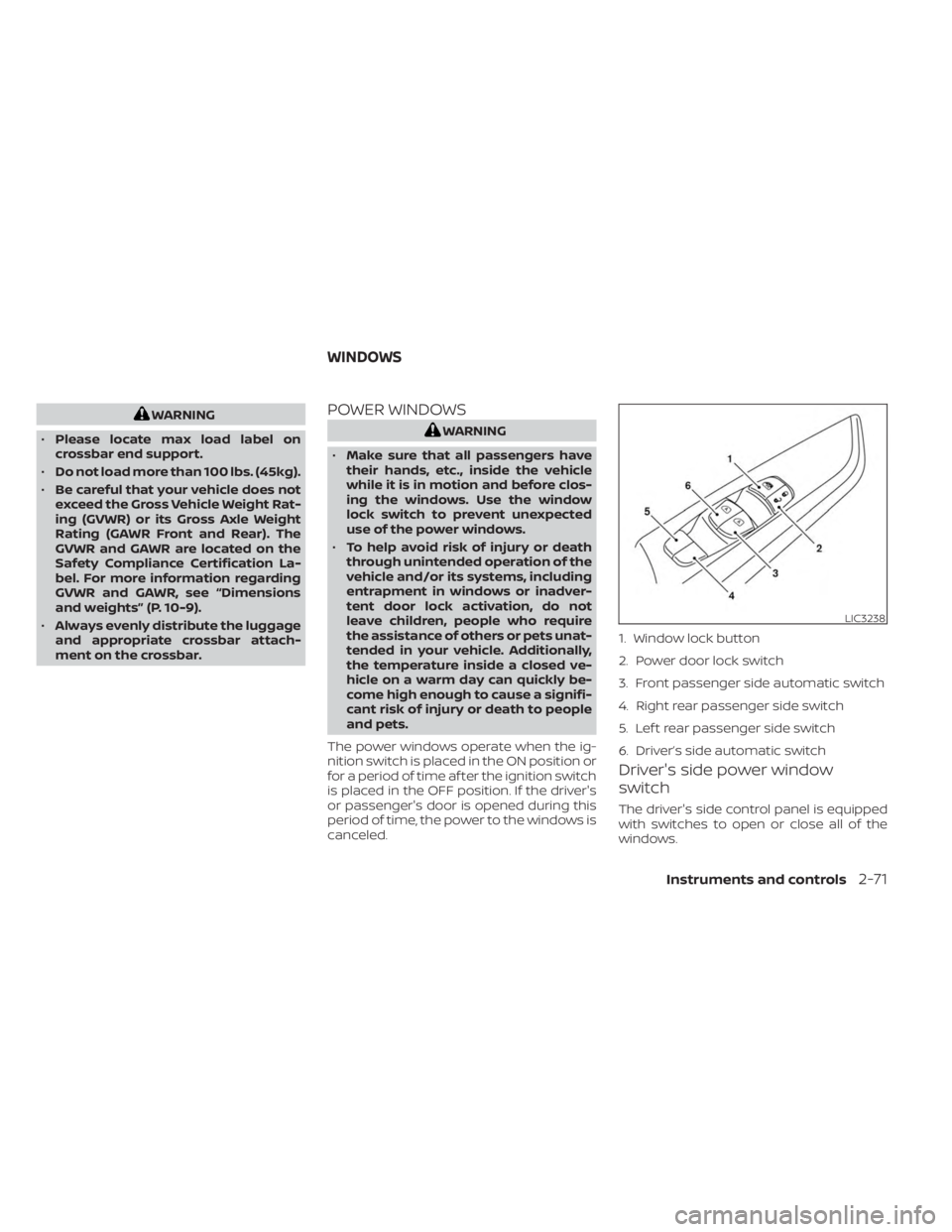
1. Window lock button
2. Power door lock switch
3. Front passenger side automatic switch
4. Right rear passenger side switch
5. Lef t rear passenger side switch
6. Driver’s side automatic switch
WINDOWS
Instruments and controls2-71
Page 186 of 558
WARNING
• Always be sure the lif tgate has been
closed securely to prevent it from
opening while driving.
•
Do not drive with the lif tgate open.
This could allow dangerous exhaust
gases to be drawn into the vehicle. For
additional information, see “Exhaust
gas (carbon monoxide)” (P. 5-4).
• Do not leave children or adults who
would normally require the assis-
tance of others alone in your vehicle.
Pets should also not be lef t alone.
They could accidently injure them-
selves or others through inadvertent
operation of the vehicle. Also, on hot,
sunny days, temperatures in a closed
vehicle could quickly become high
enough to cause severe or possibly
fatal injuries to people or animals.
• Always be sure that hands and feet
are clear of the door frame to avoid
injury while closing the lif tgate.
CAUTION
• Before opening the lif tgate, be sure
to clear away snow, ice or dust that
may be stuck to the lif tgate. If the
lif tgate is opened while materials are
still stuck to it, it may suddenly close
again due to the weight of these
materials.
• Always be sure to fully open the lif t-
gate. If it is not fully opened, it may
suddenly shut.
• Be especially careful when opening
the lif tgate in strong wind. The door
could be caught by a gust of wind
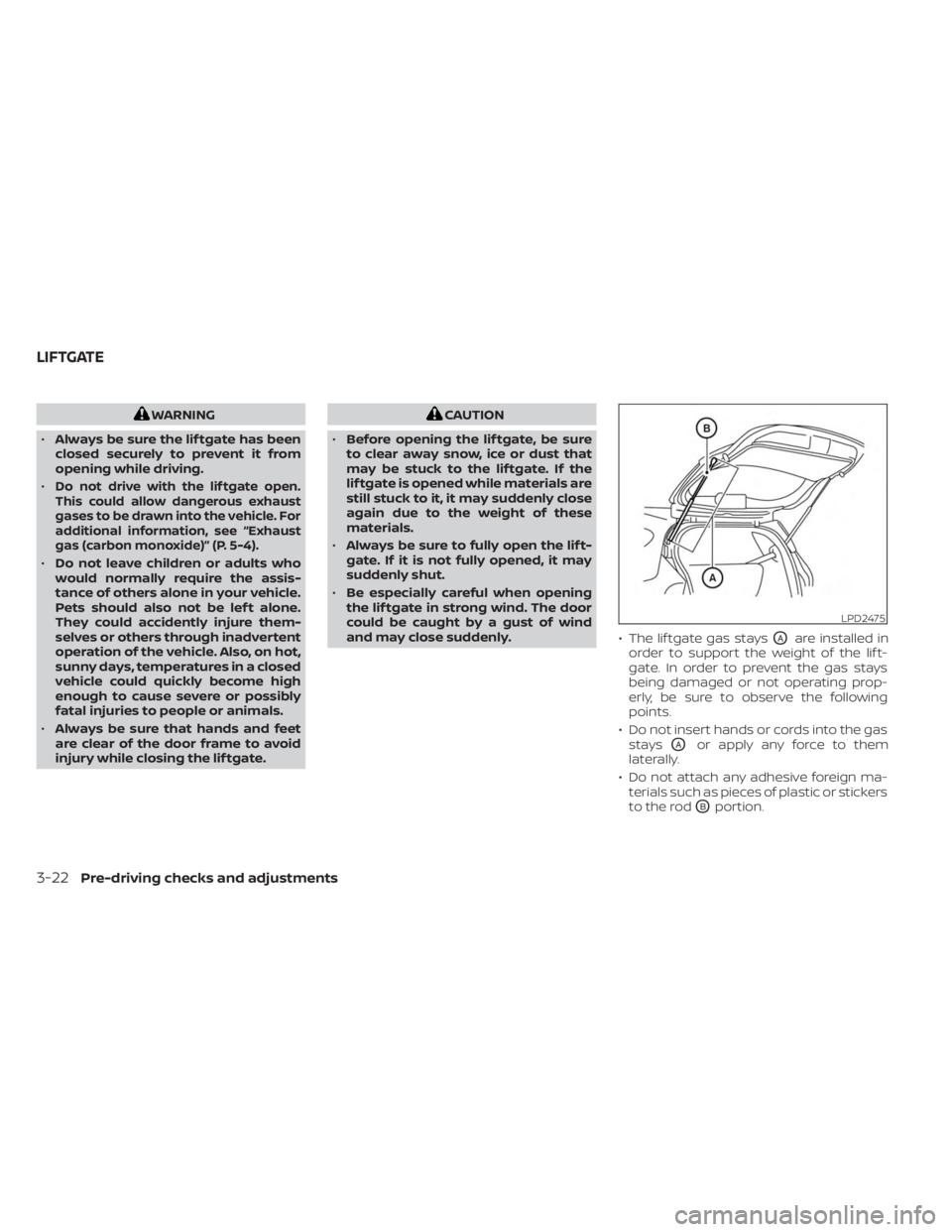
and may close suddenly. • The lif tgate gas stays
OAare installed in
order to support the weight of the lif t-
gate. In order to prevent the gas stays
being damaged or not operating prop-
erly, be sure to observe the following
points.
• Do not insert hands or cords into the gas stays
OAor apply any force to them
laterally.
• Do not attach any adhesive foreign ma- terials such as pieces of plastic or stickers
to the rod
OBportion.
LPD2475
LIFTGATE
3-22Pre-driving checks and adjustments
Page 479 of 558
The tire pressures should be
checked when the tires are cold. The
tires are considered COLD af ter the
vehicle has been parked for 3 or
more hours, or driven less than 1 mile
(1.6 km) at moderate speeds.
The TPMS with Easy-Fill Tire Alert
provides visual and audible signals
outside the vehicle for inflating tires
to the recommended COLD tire
pressure. For additional information,
see “TPMS with Easy-Fill Tire Alert”
(P. 5-8).
Incorrect tire pressure, including
under inflation, may adversely af-
fect tire life and vehicle handling.WARNING
• Improperly inflated tires can
fail suddenly and cause an
accident.
• The Gross Vehicle Weight Rat-
ing (GVWR) is located on the
F.M.V.S.S./C.M.V.S.S. certifica-
tion label. The vehicle weight
capacity is indicated on the Tire
and Loading Information label.
Do not load your vehicle be-
yond this capacity. Overload-
ing your vehicle may result in
reduced tire life, unsafe operat-
ing conditions due to prema-
ture tire failure, or unfavorable
handling characteristics and
could also lead to a serious ac-
cident. Loading beyond the
specified capacity may also re-
sult in failure of other vehicle
components. •
Before taking a long trip, or
whenever you heavily load
your vehicle, use a tire pressure
gauge to ensure that the tire
pressures are at the specified
level.
• For additional information re-
garding tires, refer to “Impor-
tant Tire Safety Information”
(US) or “Tire Safety Informa-
tion” (Canada) in the Warranty
Information Booklet.
Do-it-yourself8-29
Page 483 of 558
6. Two- or three-digit number (95):This number is the tire's load in-
dex. It is a measurement of how
much weight each tire can
support.
7. H: Tire speed rating. You should not drive the vehicle faster than
the tire speed rating.
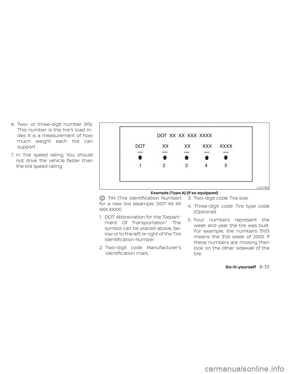
O2TIN (Tire Identification Number)
for a new tire (example: DOT XX XX
XXX XXXX)
1. DOT: Abbreviation for the “Depart- ment Of Transportation”. The
symbol can be placed above, be-
low or to the lef t or right of the Tire
Identification Number.
2. Two-digit code: Manufacturer's identification mark. 3. Two-digit code: Tire size.
4. Three-digit code: Tire type code
(Optional).
5. Four numbers represent the week and year the tire was built.
For example, the numbers 3103
means the 31st week of 2003. If
these numbers are missing then
look on the other sidewall of the
tire.
LDI2786
Example (Type A) (if so equipped)
Do-it-yourself8-33
Page 523 of 558
10 Technical and consumer information
Recommended fluids/lubricants and
capacities...................................... 10-2
Fuel recommendation ......................10-3
Engine oil and oil filter
recommendations .......................... 10-6
Air conditioner system refrigerant and
oil recommendations ....................... 10-7
Specifications .................................. 10-8
Engine ...................................... 10-8
Wheels and tires ............................ 10-9
Dimensions and weights ....................10-9
When traveling or registering in another
country ....................................... 10-10
Vehicle identification .......................... 10-10
Vehicle Identification Number (VIN)
plate ....................................... 10-10
Vehicle identification number
(chassis number) ........................... 10-10
Engine serial number .......................10-11
F.M.V.S.S./C.M.V.S.S. certification label .........10-11
Emission control information label ..........10-11 Tire and Loading Information label
.........10-12
Air conditioner specification label ..........10-12
Installing front license plate ...................10-13
Vehicle loading information ...................10-14
Terms ...................................... 10-14
Vehicle load capacity ....................... 10-15
Securing the load .......................... 10-17
Loading tips ................................ 10-18
Measurement of weights ...................10-19
Towing a trailer ................................ 10-19
Flat towing ................................. 10-19
Uniform tire quality grading ...................10-20
Emission control system warranty ............10-21
Reporting safety defects ......................10-21
Readiness for Inspection/Maintenance (I/M)
test ........................................... 10-22
Event Data Recorders (EDR) ...................10-23
Owner's Manual/Service Manual order
information ................................... 10-23
Page 531 of 558
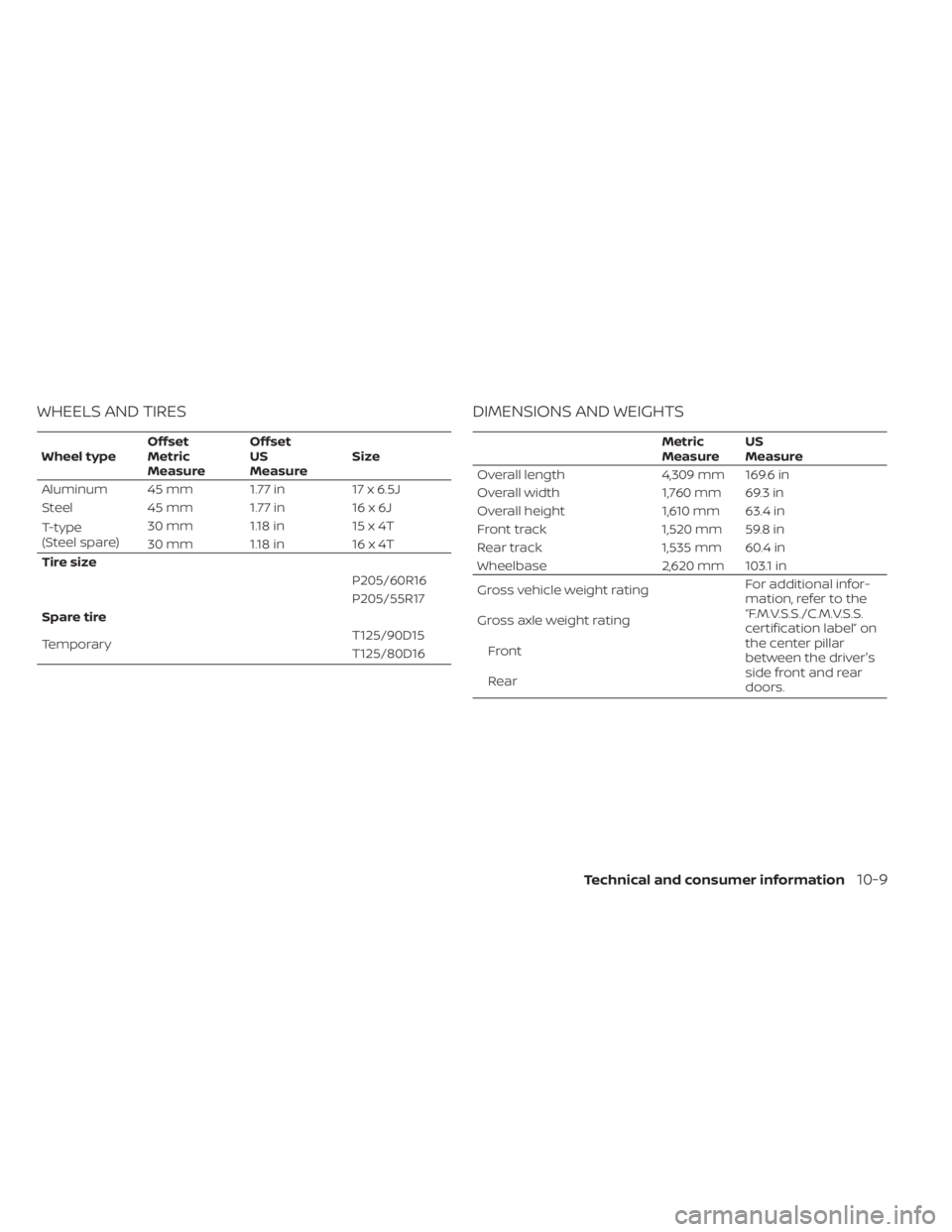
WHEELS AND TIRES
Wheel typeOffset
Metric
MeasureOffset
US
Measure
Size
Aluminum 45 mm 1.77 in 17 x 6.5J
Steel 45 mm 1.77 in 16 x 6J
T-type
(Steel spare) 30 mm 1.18 in
15 x 4T
30 mm 1.18 in 16 x 4T
Tire size P205/60R16
P205/55R17
Spare tire
Temporary T125/90D15
T125/80D16
DIMENSIONS AND WEIGHTS
Metric
MeasureUS
Measure
Overall length 4,309 mm 169.6 in
Overall width 1,760 mm 69.3 in
Overall height 1,610 mm 63.4 in
Front track 1,520 mm 59.8 in
Rear track 1,535 mm 60.4 in
Wheelbase 2,620 mm 103.1 in
Gross vehicle weight rating For additional infor-
mation, refer to the
“F.M.V.S.S./C.M.V.S.S.
certification label” on
the center pillar
between the driver's
side front and rear
doors.
Gross axle weight rating
Front
Rear
Technical and consumer information10-9