2023 NISSAN FRONTIER glove box
[x] Cancel search: glove boxPage 214 of 572

CAUTION
The lockout protection may not func-
tion under the following conditions:
• When the Intelligent Key is placed on
top of the instrument panel.
• When the Intelligent Key is placed in-
side the glove box or a storage bin.
• When the Intelligent Key is placed in-
side the door pockets.
• When the Intelligent Key is placed in-
side or near metallic materials.
Unlocking doors
1. Carry the Intelligent Key.
2. Push any door handle request switch
O1
(if so equipped).
3. The door on which the request switch (if so equipped) was pressed will unlock
and the hazard indicator lights flash
once and the outside buzzer sounds
once.
4. Push the door handle request switch
O1
(if so equipped) again within 60 seconds
to unlock all doors.
NOTE:
• If the “Selective Unlock” feature is switched to OFF using the “Vehicle
Settings” menu, all doors will unlock
upon the first request switch
O1(if so
equipped) press.
• Request switches (if so equipped) for all doors can be deactivated when the
“I-Key Door Lock (if so equipped)” set-
ting is switched to OFF in the “Vehicle
Settings” of the vehicle information
display. For additional information, see
“Vehicle information display ” (P. 2-22).
LPD3245LPD3244
3-12Pre-driving checks and adjustments
Page 230 of 572

Disconnecting the rear camera
Before removing the tailgate disconnect
the rear camera by performing the follow-
ing:
1. Open the tailgate to access the rearcamera connector bracket
O1located
on the rear sill.
2. Remove the connector bracket
O2from
the sill by pressing the locking tab in-
ward, in the direction shown, while pull-
ing the bracket apart. 3. Disconnect the chassis wiring harness
O3by pressing inward on the locking
tab, in the direction shown, while pulling
the connectors apart. Hold the connec-
tor firmly to prevent the connector in the
chassis harness from falling into the sill.
4. Take the chassis plug and bracket from the glove box and connect them to the
chassis wiring harness to avoid con-
tamination to the terminals which will
lead to malfunction of the rear camera.
5. Insert the bracket back into the sill. 6. Take the tailgate plug from the glove box
and connect it to the tailgate wiring har-
ness to avoid contamination which will
lead to malfunction of the rear camera.
7. Remove the tailgate. For additional infor- mation, see “Removing the tailgate”
(P. 3-29).
LPD2097
3-28Pre-driving checks and adjustments
Page 232 of 572

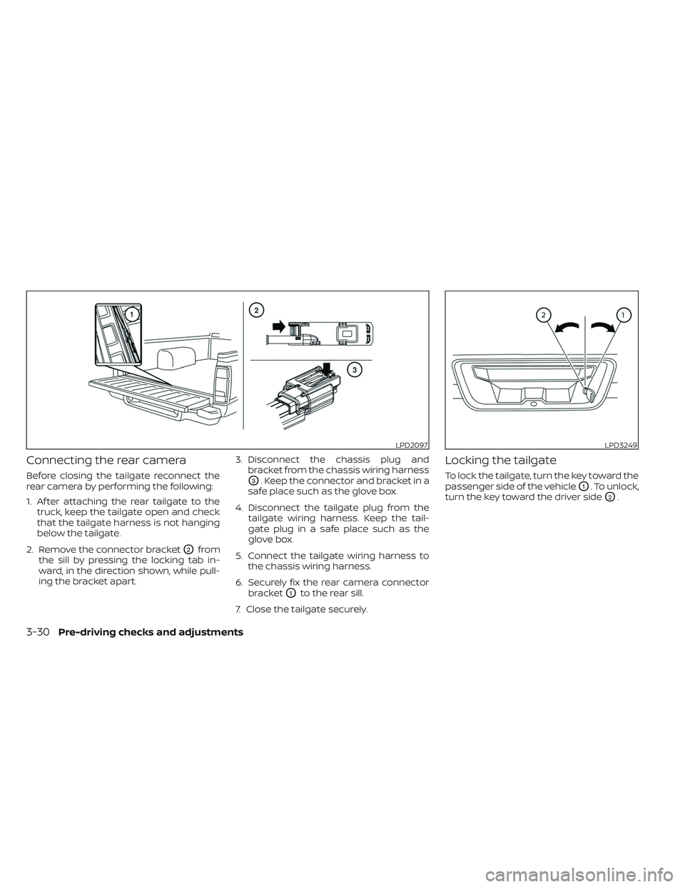
Connecting the rear camera
Before closing the tailgate reconnect the
rear camera by performing the following:
1. Af ter attaching the rear tailgate to thetruck, keep the tailgate open and check
that the tailgate harness is not hanging
below the tailgate.
2. Remove the connector bracket
O2from
the sill by pressing the locking tab in-
ward, in the direction shown, while pull-
ing the bracket apart. 3. Disconnect the chassis plug and
bracket from the chassis wiring harness
O3. Keep the connector and bracket in a
safe place such as the glove box.
4. Disconnect the tailgate plug from the tailgate wiring harness. Keep the tail-
gate plug in a safe place such as the
glove box.
5. Connect the tailgate wiring harness to the chassis wiring harness.
6. Securely fix the rear camera connector bracket
O1to the rear sill.
7. Close the tailgate securely.
Locking the tailgate
To lock the tailgate, turn the key toward the
passenger side of the vehicle
O1. To unlock,
turn the key toward the driver side
O2.
LPD2097LPD3249
3-30Pre-driving checks and adjustments
Page 294 of 572

Some indicators and warnings for opera-
tion are displayed in the meter. For addi-
tional information, see “Warning lights, indi-
cator lights and audible reminders” (P. 2-11).
OPERATING RANGE
The Intelligent Key functions can only be
used when the Intelligent Key is within the
specified operating range.
When the Intelligent Key battery is almost
discharged or strong radio waves are pres-
ent near the operating location, the Intelli-
gent Key system’s operating range be-
comes narrower and may not function
properly.If the Intelligent Key is within the operating
range, it is possible for anyone, even some-
one who does not carry the Intelligent Key,
to push the ignition switch to start the
engine.
The operating range of the engine start
function is inside of the vehicle
O1.
• The luggage area is not included in the operating range, but the Intelligent Key
may function.
• If the Intelligent Key is placed on the in- strument panel or inside the glove box,
storage bin or door pocket, the Intelligent
Key may not function.
• If the Intelligent Key is placed near the door or window outside the vehicle, the
Intelligent Key may function.
PUSH-BUTTON IGNITION SWITCH
POSITIONS
LOCK (Normal parking position)
The ignition switch can only be locked in
this position.
The ignition switch will be unlocked when it
is pushed to the ON position while carrying
the Intelligent Key.
LSD3854
5-14Starting and driving
Page 462 of 572

If replacement is required, it is recom-
mended that you visit a NISSAN dealer for
this service.The dry paper type filter element may be
cleaned and reused. Replace it according
to the maintenance log shown in the
"Maintenance and schedules" section of
this manual.
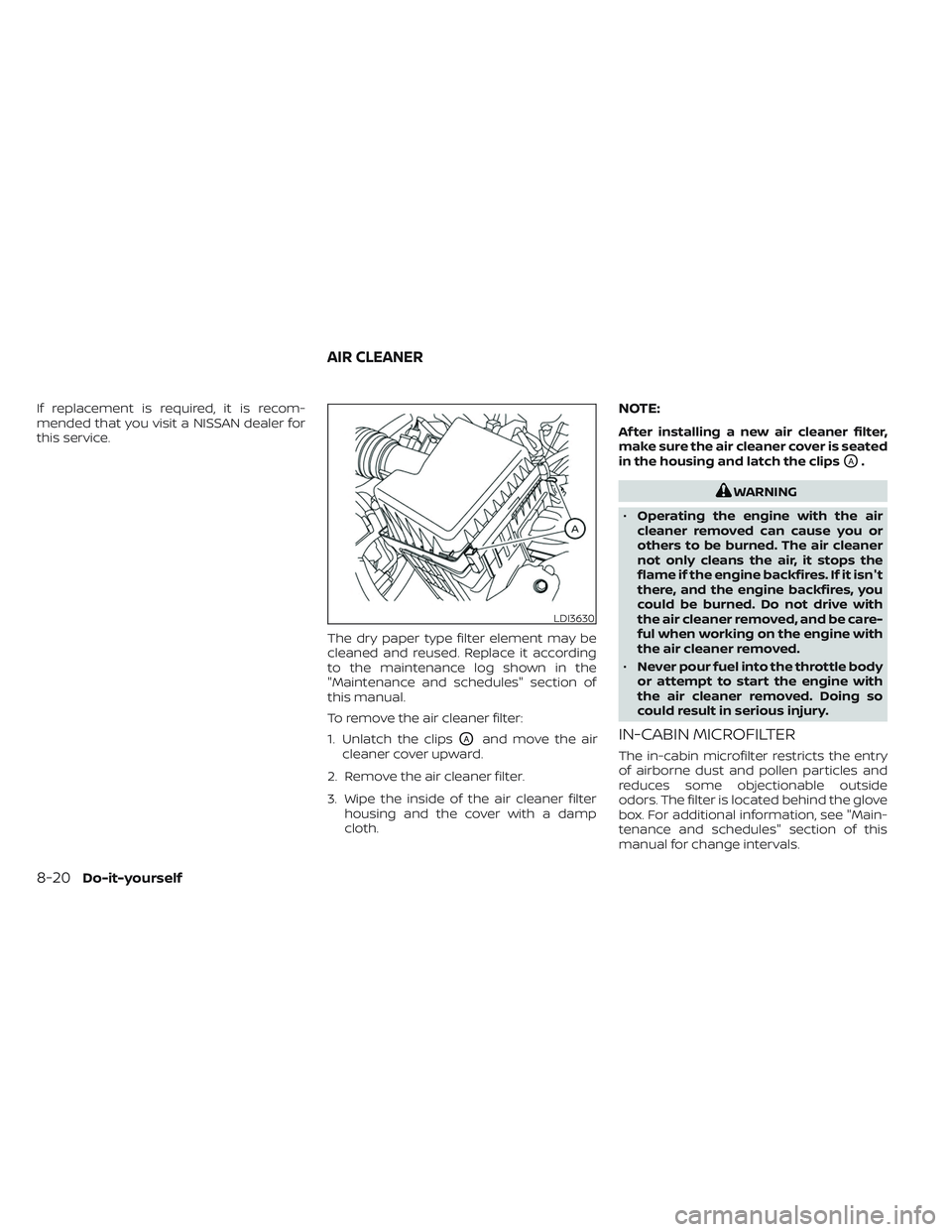
To remove the air cleaner filter:
1. Unlatch the clips
OAand move the air
cleaner cover upward.
2. Remove the air cleaner filter.
3. Wipe the inside of the air cleaner filter housing and the cover with a damp
cloth.
NOTE:
Af ter installing a new air cleaner filter,
make sure the air cleaner cover is seated
in the housing and latch the clips
OA.
WARNING
• Operating the engine with the air
cleaner removed can cause you or
others to be burned. The air cleaner
not only cleans the air, it stops the
flame if the engine backfires. If it isn't
there, and the engine backfires, you
could be burned. Do not drive with
the air cleaner removed, and be care-
ful when working on the engine with
the air cleaner removed.
• Never pour fuel into the throttle body
or attempt to start the engine with
the air cleaner removed. Doing so
could result in serious injury.
IN-CABIN MICROFILTER
The in-cabin microfilter restricts the entry
of airborne dust and pollen particles and
reduces some objectionable outside
odors. The filter is located behind the glove
box. For additional information, see "Main-
tenance and schedules" section of this
manual for change intervals.
LDI3630
AIR CLEANER
8-20Do-it-yourself
Page 467 of 572

5. If the fuse is openOA, replace it with a
new fuse
OB.
6. If a new fuse also opens, have the elec- trical system checked and repaired. It is
recommended that you visit a NISSAN
dealer for this service.
Fusible links
If the electrical equipment does not oper-
ate and fuses are in good condition, check
the fusible links. If any of these fusible links
are melted, replace with only Genuine
NISSAN parts.
PASSENGER COMPARTMENT
WARNING
Never use a fuse of a higher or lower
amperage rating than that specified on
the fuse box cover. This could damage
the electrical system or electronic con-
trol units or cause a fire. If any electrical equipment does not oper-
ate, check for an open fuse.
1. Be sure the ignition switch and the head-
light switch are OFF.
2. Open glove box and pull the fuse box covertoremove.
3. Remove the fuse with the fuse puller.
LDI0456LDI3640
Do-it-yourself8-25
Page 471 of 572

Replacing the fog light bulb (if so
equipped)
If fog light bulb replacement is required, it is
recommended that you visit a NISSAN
dealer for this service.
CAUTION
• High pressure halogen gas is sealed
inside the halogen bulb. The bulb
may break if the glass envelope is
scratched or the bulb is dropped.
• When handling the bulb, do not touch
the glass envelope.
• Use the same number and wattage
as originally installed as shown in the
chart.
• Do not leave the bulb out of the fog
light for a long period of time as dust,
moisture and smoke may enter the
fog light body and affect the perfor-
mance of the fog light.
Replacing the LED fog light bulb
(if so equipped)
If LED fog light bulb replacement is re-
quired, it is recommended that you visit a
NISSAN dealer for this service.
EXTERIOR AND INTERIOR LIGHTS
Item Wattage (W)Bulb No.*
Headlight assembly (Type A) (if so equipped)* Low/High 55/65HB5
Turn/Park 28/87444NA
Side marker ——
Headlight assembly (Type B) (if so equipped)* Low ——
High ——
Tu r n ——
Daytime Running Light (DRL)/Park ——
Side marker ——
Fog light (if so equipped)* ——
Fog light assembly (if so equipped)* Fog 35H8
Daytime Running Light (DRL) 21W21W
Map light (Type A) (if so equipped) 8—
Map light (Type B) (if so equipped)* ——
Vanity mirror light (if so equipped)* 1.4—
Room light (Type A) (if so equipped) 8—
Room light (Type B) (if so equipped)* ——
Glove box light (if so equipped)* 1—
High-mounted stop light/cargo light* 12.8912
Bed light (if so equipped)* ——
Rear combination light* Ta i l ——
Stop/turn ——
Backup ——
License plate light* ——
* It is recommended that you visit a NISSAN dealer for replacement.
Always check with the Parts Department at a NISSAN dealer for the latest parts
information.
Do-it-yourself8-29
Page 561 of 572

Forward Driving AidsSystem Temporarily
Unavailable
......2-38, 5-67, 5-88, 5-101Four-Wheel Drive...............5-109Front air bag system (See supplemental re-
straint system).................1-77Front power seat adjustment........1-4Front seats....................1-2Front-door pocket..............2-67FuelCapacities and recommended
fuel/lubricants
...............10-2Fuel economy...............5-109Fuel gauge..................2-7Fuel octane rating.............10-6Fuel recommendation..........10-4Fuel-filler cap................3-21Fuel-filler lid.................3-21Loose fuel cap warning..........2-33Fuel efficient driving tips..........5-108Fuel gauge....................2-7Fuel-filler door.................3-21Fuses......................8-23Fusible links..................8-25
G
Garage door opener, HomeLink® Universal
Transceiver........2-80, 2-81, 2-83, 2-84Gas cap.....................3-21GaugeAutomatic transmission fluid temperature
gauge
.................... .2-8
Engine coolant temperature gauge. . .2-6Engine oil pressure gauge.........2-8Fuel gauge..................2-7Odometer...................2-5Speedometer................2-5Tachometer.................2-6Trip odometer................2-5Voltmeter.................. .2-8General maintenance.............9-2Glove box....................2-71
H
Hazard warning flasher switch........6-2Head restraints.................1-9Headlight and turn signal switch.....2-43Headlight control switch...........2-43Headlights...................8-28Heated mirrors................3-26Heated seat switches............2-51Heated steering wheel switch.......2-52Heater
Heater and air conditioner (automatic) (if
so equipped)
................4-38Heater and air conditioner controls. .4-39Heater operation..........4-31, 4-41Heater and air conditioner (automatic).4-38Hill descent control switch.........2-54Hill descent control system........5-123Hill start assist system...........5-124HomeLink® Universal
Transceiver........2-80, 2-81, 2-83, 2-84
Hood release..................3-20Horn...................... .2-50
I
Idling Stop System..............5-129Ignition switch
Push-button ignition switch.......5-13Immobilizer system..........2-41, 5-16In-cabin microfilter..............8-20Increasing fuel economy..........5-109Indicator lights and audible reminders (See
warning/indicator lights and audible
reminders)
...................2-13Inside automatic anti-glare mirror. . . .3-25Instrument brightness control.......2-49Instrument panel.............0-6, 2-2Instrument panel dimmer switch.....2-49Intelligent Around View® Monitor......4-11Intelligent Cruise Control..........5-52Intelligent Driver Alertness (I-DA).....5-104Intelligent Forward Collision Warning
(I-FCW)..................... .5-92Intelligent Key system
Key operating range............3-9Key operation................3-10Mechanical key................3-3Remote keyless entry operation. . . .3-13Troubleshooting guide..........3-16Warning signals...............3-16Interior light..................2-78
11-3