2023 NISSAN ARMADA trailer
[x] Cancel search: trailerPage 12 of 604

0-4Illustrated table of contents
WAA0286X
1. Fuel-filler door (P.3-26)— Fuel information (P.10-4)
2. Antenna (P.4-43)
3. Rear combination light (P.8-24)
4. Rear window defroster (P.2-45)
5. Satellite antenna (P.4-44)
6. Rear view camera (P.4-4, P.4-12) 7. Intelligent Rear View Mirror camera (if so
equipped) (P.3-31)
8. High-mounted stop light (P.8-24)
9. Liftgate (P.3-22) — Intelligent Key system (P.3-7)
10. Rear window wiper and washer
— Switch operation (P.2-45) — Window washer fluid (P.8-10)
11. Spare tire (under the vehicle) (P.6-3)
12. Sonar sensors — Camera aiding sonar function (models
with Intelligent Around View® Monitor)
(P.4-26)
— Intelligent Back-up Intervention (I-BI) (if
so equipped) (P.5-63)
— Sonar system (if so equipped) (P.5-136)
13. Towing hook (P.6-19)
14. Trailer hitch (P.10-24)
EXTERIOR REAR
Page 15 of 604

WAA0289X
1. Side ventilator (P.4-36)
2. Meters and gauges (P.2-6)
3. Center ventilator (P.4-36)
4. Audio system (See NissanConnect® Own-er’s Manual)
5. Touch screen display (See NissanCon- nect® Owner’s Manual) — Intelligent Around View® Monitor (if so
equipped) (P.4-12)
— RearView Monitor (if so equipped)
(P.4-4)
— Navigation system (if so equipped) (See
NissanConnect® Owner’s Manual)
6. Front passenger air bag status light (P.1-63) 7. Hazard warning flasher switch (P.6-2)
8. Defroster switch (P.2-45)/Deicer switch (if
so equipped) (P.2-46)
9. Front passenger supplemental air bag (P.1-54)
10. Fuse box (P.8-20)
11. Parking brake (P.5-22)
12. Hood release handle (P.3-21)
13. Steering wheel — Horn (P.2-55)
— Driver supplemental air bag (P.1-54)
— Power steering (P.5-141)
14. Driver supplemental knee air bag (P.1-54)
15. Push-button ignition switch (P.5-13)
16. Climate controlled seat switch (if so equipped) (P.2-57)/Heated seat switch (if
so equipped) (P.2-55)
17. Wireless charger (if so equipped) (P.2-65)
18. Trailer Brake Controller Unit (TBCU) (if so equipped) (P.2-60)
19. USB connection ports (See NissanCon- nect® Owner’s Manual)
20. Power outlet (P.2-62)
21. Cup holder (P.2-69)
22. Heater and air conditioner (P.4-37)
23. Glove box (P.2-71)
24. Front passenger supplemental knee air bag (P.1-54)
Illustrated table of contents0-7
INSTRUMENT PANEL
Page 96 of 604

TOW mode switch ..................................................................... 2-59
Vehicle Dynamic Control (VDC) OFF switch ......... 2-60
Trailer Brake Controller Unit (TBCU) (if
so equipped) ........................................................................\
.......... 2-60
Rear door alert ........................................................................\
.... 2-61
Power outlet ........................................................................\
.......... 2-62USB (Universal Serial Bus)
charging connector .......................................................... 2-64
Wireless charger (if so equipped) ........................... 2-65
Emergency Call (SOS) button (if
so equipped) ........................................................................\
.......... 2-67
Emergency support .......................................................... 2-67
Storage ........................................................................\
...................... 2-69 Cup holders ........................................................................\
..... 2-69
Sunglasses holder .............................................................. 2-71
Glove box ........................................................................\
........... 2-71
Console box ........................................................................\
..... 2-72
Coat hooks ........................................................................\
....... 2-73
Luggage hooks ..................................................................... 2-73
Cargo floor box .................................................................... 2-74
Roof rack (if so equipped) ............................................ 2-74
Windows ........................................................................\
.................... 2-75 Power windows .................................................................... 2-75
Moonroof (if so equipped) .................................................. 2-78
Power moonroof ................................................................. 2-78
Welcome light (if so equipped) ....................................... 2-80 Battery saver system ..................................................... 2-80 Interior lights ........................................................................\
........ 2-81
Interior light switch ........................................................ 2-81
Console light ........................................................................\
2-82
Map lights ........................................................................\
....... 2-82
Rear personal lights ....................................................... 2-82
Vanity mirror lights ................................................................. 2-83
Cargo light ........................................................................\
............. 2-83
HomeLink® Universal Transceiver (Type A) (if
so equipped) ........................................................................\
......... 2-83 Programming HomeLink® ......................................... 2-84
Programming HomeLink® for Canadian
customers and gate openers ................................. 2-85
Operating the HomeLink®
Universal Transceiver .................................................... 2-86
Programming troubleshooting ............................. 2-86
Clearing the programmed information .......... 2-86
Reprogramming a single
HomeLink® button ........................................................... 2-86
If your vehicle is stolen ................................................ 2-87
HomeLink® Universal Transceiver (Type B) (if
so equipped) ........................................................................\
......... 2-87
Programming HomeLink® ......................................... 2-88
Using the garage door
two-way communication ........................................... 2-91
Programming HomeLink® for Canadian
customers and gate openers ................................. 2-91
Operating the HomeLink®
Universal Transceiver .................................................... 2-92
Page 99 of 604

WAA0289X
1. Side ventilator
2. Meters and gauges
3. Center ventilator
4. Audio system (See NissanConnect® Own-er’s Manual)
5. Touch screen display (See NissanCon- nect® Owner’s Manual) — Intelligent Around View® Monitor (if so
equipped)
— RearView Monitor (if so equipped)
— Navigation system (if so equipped) (See
NissanConnect® Owner’s Manual)
6. Front passenger air bag status light
7. Hazard warning flasher switch 8. Defroster switch/Deicer switch (if so
equipped)
9. Front passenger supplemental air bag
10. Fuse box
11. Parking brake
12. Hood release handle
13. Steering wheel — Horn
— Driver supplemental air bag
— Power steering
14. Driver supplemental knee air bag
15. Push-button ignition switch
16. Climate controlled seat switch (if so equipped)/Heated seat switch (if so
equipped)
17. Wireless charger (if so equipped)
18. Trailer Brake Controller Unit (TBCU) (if so equipped)
19. USB connection ports (See NissanCon- nect® Owner’s Manual)
20. Power outlet
21. Cup holder
22. Heater and air conditioner
23. Glove box
24. Front passenger supplemental knee air bag
Instruments and controls2-5
INSTRUMENT PANEL
Page 153 of 604

close to either the left or the right of a
traveling lane with detectable lane mar-
kers. (See “Lane Departure Warning (LDW)”
(P.5-26).)
The BSW system will turn on the side
indicator lights, on the outside mirrors, if
the radar sensors detect a vehicle in the
detection zone. If the turn signal is
activated in the direction of the detected
vehicle, a chime sounds twice and the
side indicator light will flash. (See “Blind
Spot Warning (BSW)” (P.5-38).)
SIC4454
For driving or starting the vehicle on
snowy roads or slippery areas, push on
the SNOW mode switch. The SNOW mode
indicator will illuminate. When the SNOW
mode is activated, engine output is con-
trolled to avoid wheel spin.
Push off the SNOW mode for normal
driving.
NOTE:
When the SNOW mode is activated, the
I-LI, I-BSI, and ICC systems will be turned
off automatically.
SIC4474
TOW MODE should be used when pulling
a heavy trailer or hauling a heavy load.
Driving the vehicle in TOW MODE with no
trailer/load or light trailer/light load will
not cause any damage. However, fuel
economy may be reduced, and the trans-
mission/engine driving characteristics
may feel unusual.
Push the TOW MODE switch to activate
TOW MODE. The indicator light on the
TOW MODE switch illuminates when TOW
MODE is selected. Push the TOW MODE
switch again to turn TOW MODE OFF.
TOW MODE is automatically canceled
when the ignition switch is placed in the
OFF position.
Instruments and controls2-59
SNOW MODE SWITCHTOW MODE SWITCH
Page 154 of 604

2-60Instruments and controls
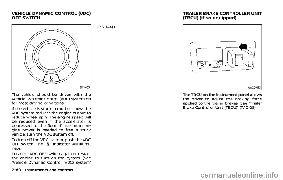
SIC4455
The vehicle should be driven with the
Vehicle Dynamic Control (VDC) system on
for most driving conditions.
If the vehicle is stuck in mud or snow, the
VDC system reduces the engine output to
reduce wheel spin. The engine speed will
be reduced even if the accelerator is
depressed to the floor. If maximum en-
gine power is needed to free a stuck
vehicle, turn the VDC system off.
To turn off the VDC system, push the VDC
OFF switch. The
indicator will illumi-
nate.
Push the VDC OFF switch again or restart
the engine to turn on the system. (See
“Vehicle Dynamic Control (VDC) system” (P.5-144).)
WAC0619X
The TBCU on the instrument panel allows
the driver to adjust the braking force
applied to the trailer brakes. See “Trailer
Brake Controller Unit (TBCU)” (P.10-28).
VEHICLE DYNAMIC CONTROL (VDC)
OFF SWITCH
TRAILER BRAKE CONTROLLER UNIT
(TBCU) (if so equipped)
Page 215 of 604

the vehicle when refueling.
. Do not attempt to top off the fuel
tank after the fuel pump nozzle
shuts off automatically. Contin-
ued refueling may cause fuel
overflow, resulting in fuel spray
and possibly a fire.
. Use only an original equipment
type fuel-filler cap as a replace-
ment. It has a built-in safety valve
needed for proper operation of
the fuel system and emission
control system. An incorrect cap
can result in a serious malfunc-
tion and possible injury. It could
also cause the malfunction indi-
cator light to come on.
. Never pour fuel into the throttle
body to attempt to start your
vehicle.
. Do not fill a portable fuel contain-
er in the vehicle or trailer. Static
electricity can cause an explosion
of flammable liquid, vapor or gas
in any vehicle or trailer. To reduce
the risk of serious injury or death
when filling portable fuel contain-
ers:
— Always place the container on
the ground when filling. — Do not use electronic devices
when filling.
— Keep the pump nozzle in con- tact with the container while
you are filling it.
— Use only approved portable fuel containers for flammable
liquid.
CAUTION
. If fuel is spilled on the vehicle
body, flush it away with water to
avoid paint damage.
. Insert the cap straight into the
fuel-filler tube, then tighten until
the fuel-filler cap clicks. Failure to
tighten the fuel-filler cap properly
may cause the
malfunction
indicator light (MIL) to illuminate.
If the
light illuminates be-
cause the fuel-filler cap is loose
or missing, tighten or install the
cap and continue to drive the
vehicle. The
light should turn
off after a few driving trips. If the
light does not turn off after a
few driving trips, have the vehicle
inspected. It is recommended you visit a NISSAN dealer for this
service.
. The Loose Fuel Cap warning will
appear if the fuel-filler cap is not
properly tightened. It may take a
few driving trips for the message
to be displayed. Failure to tighten
the fuel-filler cap properly after
the Loose Fuel Cap warning ap-
pears may cause the
Mal-
function Indicator Light (MIL) to
illuminate.
Turn the cap counterclockwise to re-
move. To tighten, turn the cap clockwise
until a single click is heard.
Pre-driving checks and adjustments3-27
Page 264 of 604

4-34Monitor, heater, air conditioner, audio, phone and voice recognition systems
system will turn back on.
The sonar, the Rear Automatic Braking
(RAB), and the Intelligent Back-up Inter-
vention (I-BI) systems will also turn back
on at the same time.
To enable or disable the MOD system, use
the camera settings menu. See “MOD
function settings” (P.4-34).
MOD FUNCTION SETTINGS
The MOD function settings can be chan-
ged using the following procedures.
1. Push the MENU button on the DisplayCommander.
2. Touch the “Settings” key on the touch screen display.
3. Touch the “Camera” key.
4. Touch the “Camera” key.
Available setting items:
Moving Object Detection:
When this item is turned on, the MOD
system is activated. When this item is
turned off (indicator turns off), the MOD
system is deactivated.
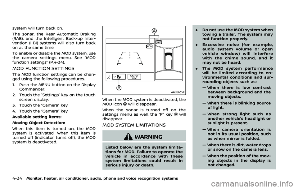
WAE0665X
When the MOD system is deactivated, the
MOD iconwill disappear.
When the sonar is turned off on the
settings menu as well, the “P” key
will
disappear.
MOD SYSTEM LIMITATIONS
WARNING
Listed below are the system limita-
tions for MOD. Failure to operate the
vehicle in accordance with these
system limitations could result in
serious injury or death. .
Do not use the MOD system when
towing a trailer. The system may
not function properly.
. Excessive noise (for example,
audio system volume or open
vehicle window) will interfere
with the chime sound, and it
may not be heard.
. The MOD system performance
will be limited according to en-
vironmental conditions and sur-
rounding objects such as:
— When there is low contrast
between background and the
moving objects.
— When there is blinking source of light.
— When strong light such as another vehicle’s headlight or
sunlight is present.
— When camera orientation is not in its usual position, such
as when mirror is folded.
— When there is dirt, water drops or snow on the camera lens.
— When the position of the mov- ing objects in the display is
not changed.