2023 NISSAN ARMADA ESP
[x] Cancel search: ESPPage 328 of 604

5-16Starting and driving
.Make sure the area around the vehicle
is clear.
. Check fluid levels such as engine oil,
coolant, brake fluid and window
washer fluid as frequently as possible,
or at least whenever you refuel.
. Check that all windows and lights are
clean.
. Visually inspect tires for their appear-
ance and condition. Also check tires
for proper inflation.
. Lock all doors.
. Position seat and adjust head re-
straints/headrests.
. Adjust inside and outside mirrors.
. Fasten seat belts and ask all passen-
gers to do likewise.
. Check the operation of warning lights
when the ignition switch is pushed to
the ON position. (See “Warning lights,
indicator lights and audible remin-
ders” (P.2-11).) 1. Apply the parking brake.
2. Move the shift lever to the P (Park) or N
(Neutral) position. (P is recommended.)
The starter is designed not to operate
unless the shift lever is in either of the
above positions.
3. Push the ignition switch to the ON position. Firmly depress the brake
pedal and push the ignition switch to
start the engine.
To start the engine immediately, push
and release the ignition switch while
depressing the brake pedal with the
ignition switch in any position.
.If the engine is very hard to start inextremely cold weather or when
restarting, depress the accelerator
pedal a little (approximately 1/3 to
the floor) and while holding, crank
the engine. Release the accelerator
pedal when the engine starts.
.If the engine is very hard to startbecause it is flooded, depress the
accelerator pedal all the way to the
floor and hold it. Push the ignition
switch to the ON position to start
cranking the engine. After 5 or 6
seconds, stop cranking by pushing
the ignition switch to OFF. After
cranking the engine, release the
accelerator pedal. Crank the engine
with your foot off the accelerator pedal
by depressing the brake
pedal and pushing the push-button
ignition switch to start the engine.
If the engine starts, but fails to run,
repeat the above procedure.
CAUTION
Do not operate the starter for more
than 15 seconds at a time. If the
engine does not start, push the
ignition switch to OFF and wait 10
seconds before cranking again,
otherwise the starter could be da-
maged.
4. Warm-up
Allow the engine to idle for at least 30
seconds after starting. Do not race the
engine while warming it up. Drive at
moderate speed for a short distance
first, especially in cold weather. In cold
weather, keep the engine running for
a minimum of 2 - 3 minutes before
shutting it off. Starting and stopping
the engine over a short period of time
may make the vehicle more difficult to
start.
When racing the engine up to 4,000
rpm or more under the no load
condition, the engine will enter the
BEFORE STARTING THE ENGINE STARTING THE ENGINE
Page 330 of 604
5-18Starting and driving
If:
1. The engine coolant temperature is notreduced.
2. The air conditioning cooling function does not turn back ON.
3. The engine oil pressure warning light
illuminates or engine coolant
temperature gauge does not return
to the normal range from the H
position, this may indicate a malfunc-
tion. Move the vehicle off the road to a
safe area and allow the engine to cool.
If after checking the oil and coolant,
the
remains on or engine coolant
temperature does not return to the
normal range, do not continue to
drive. It is recommended you contact
a NISSAN dealer.
The Malfunction Indicator Light (MIL)
may also come ON. You do not need to
have your vehicle towed, unless it re-
mains on, but have it inspected soon. It is
recommended you contact a NISSAN
dealer for this service. See “Warning lights,
indicator lights and audible reminders”
(P.2-11).
WARNING
Overheating can result in reduced
engine power and vehicle speed.
The reduced speed may be lower
than other traffic, which could in-
crease the chance of a collision. Be
especially careful when driving. If the
vehicle cannot maintain a safe driv-
ing speed, pull to the side of the road
in a safe area. Allow the engine to
cool and return to normal operation.
See “If your vehicle overheats” (P.6-
14).
CAUTION
Running the engine with the engine
oil pressure warning light on could
cause serious damage to the engine
almost immediately. Such damage is
not covered by warranty. Turn off the
engine as soon as it is safe to do so.
AUTOMATIC TRANSMISSION
7 speed automatic transmission
The automatic transmission in your vehi-
cle is electronically controlled by a trans-
mission control module to produce
maximum efficiency and smooth opera-
tion.
Shown on the following pages are the
recommended operating procedures for
this transmission. Follow these proce-
dures for maximum vehicle performance
and driving enjoyment.
Starting the vehicle
After starting the engine, fully depress the
foot brake pedal and push the shift lever
button before shifting the shift lever to
the R (Reverse), N (Neutral), D (Drive) or
Manual shift mode position. Be sure the
vehicle is fully stopped before attempting
to shift the shift lever.
This automatic transmission model is
designed so that the foot brake pedal
must be depressed before shifting from
P (Park) to any drive position while the
ignition switch position is ON.
The shift lever cannot be moved out of
the P (Park) position and into any of the
other gear positions if the ignition
switch is pushed to the LOCK, OFF or
ACC position.
Page 335 of 604
SPA2331
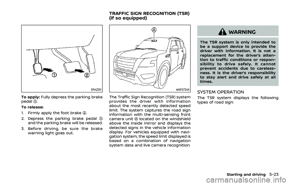
To apply:Fully depress the parking brake
pedal.
To release:
1. Firmly apply the foot brake
.
2. Depress the parking brake pedal
and the parking brake will be released.
3. Before driving, be sure the brake warning light goes out.
WAF0734X
The Traffic Sign Recognition (TSR) system
provides the driver with information
about the most recently detected speed
limit. The system captures the road sign
information with the multi-sensing front
camera unit
located on the windshield
above the inside mirror and displays the
detected signs in the vehicle information
display. For vehicles equipped with navi-
gation system, the speed limit displayed is
based on a combination of navigation
system data and live camera recognition.
WARNING
The TSR system is only intended to
be a support device to provide the
driver with information. It is not a
replacement for the driver’s atten-
tion to traffic conditions or respon-
sibility to drive safely. It cannot
prevent accidents due to careless-
ness. It is the driver’s responsibility
to stay alert and drive safely at all
times.
SYSTEM OPERATION
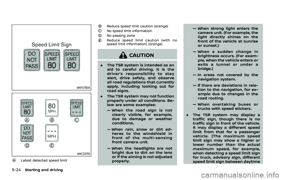
The TSR system displays the following
types of road sign:
Starting and driving5-23
TRAFFIC SIGN RECOGNITION (TSR)
(if so equipped)
Page 336 of 604
5-24Starting and driving
WAF0780X
WAC0215X
Latest detected speed limit
Reduce speed limit caution (orange)No speed limit informationNo passing zoneReduce speed limit caution (with no
speed limit information) (orange)
CAUTION
.The TSR system is intended as an
aid to careful driving. It is the
driver’s responsibility to stay
alert, drive safely, and observe
all road regulations that currently
apply, including looking out for
road signs.
. The TSR system may not function
properly under all conditions. Be-
low are some examples:
— When the road sign is not
clearly visible, for example,
due to damage or weather
conditions.
— When rain, snow or dirt ad- heres to the windshield in
front of the multi-sensing
front camera unit.
— When the headlights are not bright due to dirt on the lens
or if the aiming is not adjusted
properly. — When strong light enters the
camera unit. (For example, the
light directly shines on the
front of the vehicle at sunrise
or sunset.)
— When a sudden change in brightness occurs. (For exam-
ple, when the vehicle enters or
exits a tunnel or under a
bridge.)
— In areas not covered by the navigation system.
— If there are deviations in rela- tion to the navigation, for ex-
ample due to changes in the
road routing.
— When overtaking buses or trucks with speed stickers.
. The TSR system may display a
traffic sign, though there is no
traffic sign in front of the vehicle.
It may display a different speed
limit from that for a passenger
vehicle. (The maximum speed
limit sign may show a higher or
lower number than the actual
maximum speed, for example,
when detecting a speed limit sign
for truck, advisory sign, different
speed limit sign between daytime
Page 338 of 604
5-26Starting and driving
thebutton to select “Driver Assis-
tance”. Then push the OK.
2. Select “Speed Limit Sign” and push the OK to turn the system on or off.
SYSTEM TEMPORARILY UNAVAIL-
ABLE
If the vehicle is parked in direct sunlight
under high temperature conditions (over
approximately 104°F (40°C) and then
started, the TSR system may be deacti-
vated automatically. The “Unavailable
High Cabin Temperature” warning mes-
sage will appear in the vehicle informa-
tion display.
Action to take:
When the interior temperature is reduced,
the TSR system will resume operating
automatically.
SYSTEM MALFUNCTION
If the TSR system malfunctions it will be
turned off automatically and the TSR
“Malfunction See Owner’s Manual” warn-
ing message will appear in the vehicle
information display.
Action to take
If the warning message appears, pull off
the road at a safe location and stop the
vehicle. Turn the engine off and restart
the engine. If the warning message con-
tinues to appear, have the system checked by a NISSAN dealer.
SYSTEM MAINTENANCE
The TSR system uses the same multi-
sensing front camera unit that is used by
the Lane Departure Warning (LDW) sys-
tem, located above the inside mirror. (See
“System maintenance” (P.5-31).)
WARNING
Failure to follow the warnings and
instructions for proper use of the
LDW system could result in serious
injury or death.
.
This system is only a warning
device to inform the driver of a
potential unintended lane depar-
ture. It will not steer the vehicle or
prevent loss of control. It is the
driver’s responsibility to stay
alert, drive safely, keep the vehi-
cle in the traveling lane, and be in
control of the vehicle at all times.
LANE DEPARTURE WARNING (LDW)
Page 343 of 604
SSD0453
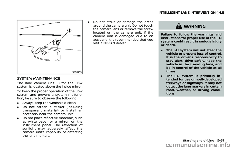
SYSTEM MAINTENANCE
The lane camera unitfor the LDW
system is located above the inside mirror.
To keep the proper operation of the LDW
system and prevent a system malfunc-
tion, be sure to observe the following:
. Always keep the windshield clean.
. Do not attach a sticker (including
transparent material) or install an
accessory near the camera unit.
. Do not place reflective materials, such
as white paper or a mirror, on the
instrument panel. The reflection of
sunlight may adversely affect the
camera unit’s capability of detecting
the lane markers. .
Do not strike or damage the areas
around the camera unit. Do not touch
the camera lens or remove the screw
located on the camera unit. If the
camera unit is damaged due to an
accident, it is recommended that you
visit a NISSAN dealer.
WARNING
Failure to follow the warnings and
instructions for proper use of the I-LI
system could result in serious injury
or death.
.The I-LI system will not steer the
vehicle or prevent loss of control.
It is the driver’s responsibility to
stay alert, drive safely, keep the
vehicle in the traveling lane, and
be in control of the vehicle at all
times.
. The I-LI system is primarily in-
tended for use on well-developed
freeways or highways. It may not
detect the lane markers in certain
road, weather, or driving condi-
tions.
Starting and driving5-31
INTELLIGENT LANE INTERVENTION (I-LI)
Page 357 of 604

WAF0721X
SYSTEM MAINTENANCE
The two radar sensorsfor the BSW
system are located near the rear bumper.
Always keep the area near the radar
sensors clean.
The radar sensors may be blocked by
temporary ambient conditions such as
splashing water, mist or fog.
The blocked condition may also be
caused by objects such as ice, frost or
dirt obstructing the radar sensors.
Check for and remove objects obstruct-
ing the area around the radar sensors.
Do not attach stickers (including trans-
parent material), install accessories or apply additional paint near the radar
sensors.
Do not strike or damage the area around
the radar sensors.
See a NISSAN dealer or other authorized
repair shop if the area around the radar
sensors is damaged due to a collision.
Radio frequency statement
For USA:
FCC ID: OAYSRR3B
This device complies with Part 15 of the
FCC Rules. Operation is subject to the
following two conditions:
(1) this device may not cause harmful inter-
ference, and
(2) this device must accept any interference received, including interference that may
cause undesired operation.
CAUTION TO USERS
Changes or modifications not expressly
approved by the party responsible for
compliance could void the user’s author-
ity to operate the equipment.
For Canada:
This device complies with Industry Cana-
da licence-exempt RSS standard(s). Op-
eration is subject to the following two
conditions: (1) this device may not cause
interference, and (2) this device must accept any interference, including inter-
ference that may cause undesired opera-
tion of the device.
Frequency bands: 24.05 – 24.25 Ghz
The field strength of SRR3-B is below 250
millivolts/m measured at 3 metres with
an average detector.
This device contains licence-exempt
transmitter(s)/receiver(s) that comply
with Innovation, Science and Economic
Development Canada’s licence-exempt
RSS(s). Operation is subject to the follow-
ing two conditions:
1. This device may not cause interference.
2. This device must accept any interfer-
ence, including interference that may
cause undesired operation of the device.
Radiofrequency radiation exposure infor-
mation:
This equipment complies with radiation
exposure limits set forth for an uncon-
trolled environment. This equipment
should be installed and operated with
minimum distance of 20 cm between the
radiator and your body.
Starting and driving5-45
Page 368 of 604
5-56Starting and driving
Radio frequency statement
For USA:
FCC ID: OAYSRR3B
This device complies with Part 15 of the
FCC Rules. Operation is subject to the
following two conditions:
(1) this device may not cause harmful inter-ference, and
(2) this device must accept any interference received, including interference that may
cause undesired operation.
CAUTION TO USERS
Changes or modifications not expressly
approved by the party responsible for
compliance could void the user’s author-
ity to operate the equipment.
For Canada:
This device complies with Industry Cana-
da licence-exempt RSS standard(s). Op-
eration is subject to the following two
conditions: (1) this device may not cause
interference, and (2) this device must
accept any interference, including inter-
ference that may cause undesired opera-
tion of the device.
Frequency bands: 24.05 – 24.25 Ghz
The field strength of SRR3-B is below 250
millivolts/m measured at 3 metres with
an average detector. This device contains licence-exempt
transmitter(s)/receiver(s) that comply
with Innovation, Science and Economic
Development Canada’s licence-exempt
RSS(s). Operation is subject to the follow-
ing two conditions:
1. This device may not cause interference.
2. This device must accept any interfer-
ence, including interference that may
cause undesired operation of the device.
Radiofrequency radiation exposure infor-
mation:
This equipment complies with radiation
exposure limits set forth for an uncon-
trolled environment. This equipment
should be installed and operated with
minimum distance of 20 cm between the
radiator and your body.