2023 NISSAN ALTIMA light
[x] Cancel search: lightPage 202 of 644
•The Loose Fuel Cap warning mes-
sage will be displayed/warning will
appear if the fuel-filler cap is not
properly tightened. It may take a few
driving trips for the message to be
displayed. Failure to tighten the fuel-
filler cap properly af ter the Loose
Fuel Cap warning message is
displayed/warning appears may
cause the
Malfunction Indicator
Light (MIL) to illuminate.
• Failure to tighten the fuel-filler cap
properly may cause the
Mal-
function Indicator Light (MIL) to illu-
minate. If the
light illuminates
because the fuel-filler cap is loose or
missing, tighten or install the cap and
continue to drive the vehicle. The
light should turn off af ter a few
driving trips. If thelight does not
turn off af ter a few driving trips, have
the vehicle inspected. It is recom-
mended that you visit a NISSAN
dealer for this service.
• For additional information, see “Mal-
function Indicator Light (MIL)”
(P. 2-15).
• If fuel is spilled on the vehicle body,
flush it away with water to avoid
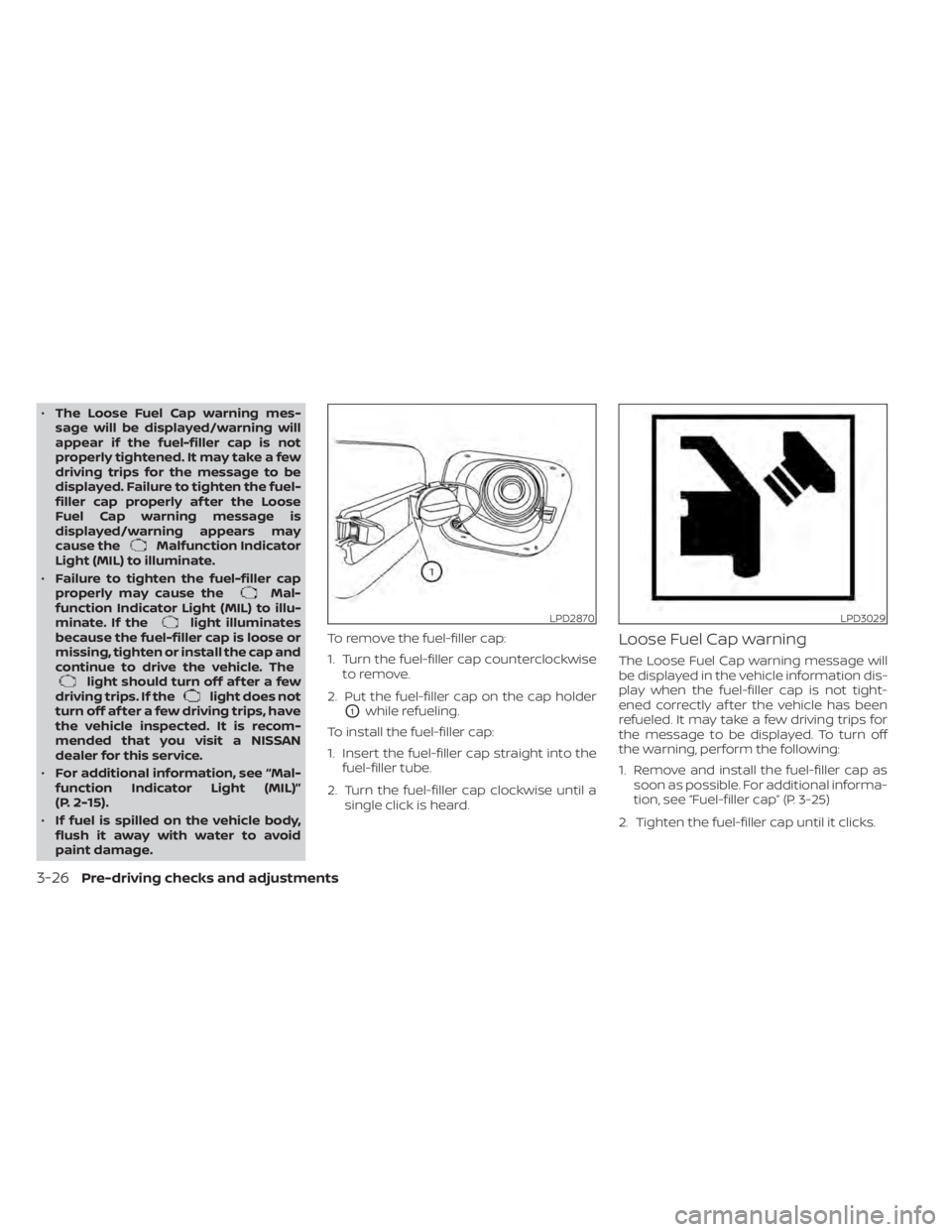
paint damage. To remove the fuel-filler cap:
1. Turn the fuel-filler cap counterclockwise
to remove.
2. Put the fuel-filler cap on the cap holder
O1while refueling.
To install the fuel-filler cap:
1. Insert the fuel-filler cap straight into the fuel-filler tube.
2. Turn the fuel-filler cap clockwise until a single click is heard.
Loose Fuel Cap warning
The Loose Fuel Cap warning message will
be displayed in the vehicle information dis-
play when the fuel-filler cap is not tight-
ened correctly af ter the vehicle has been
refueled. It may take a few driving trips for
the message to be displayed. To turn off
the warning, perform the following:
1. Remove and install the fuel-filler cap assoon as possible. For additional informa-
tion, see “Fuel-filler cap” (P. 3-25)
2. Tighten the fuel-filler cap until it clicks.
LPD2870LPD3029
3-26Pre-driving checks and adjustments
Page 205 of 644
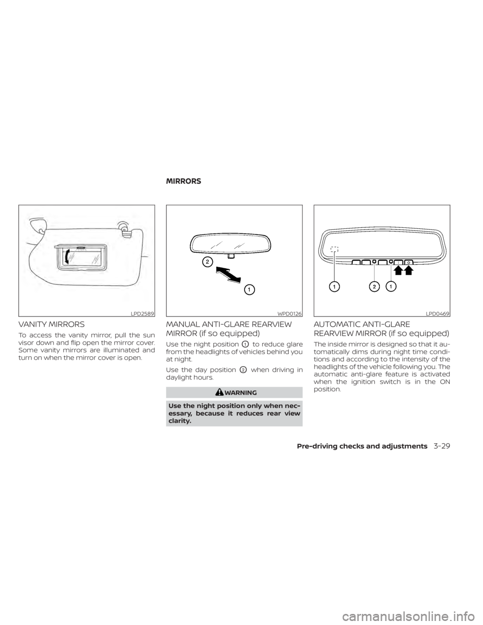
VANITY MIRRORS
To access the vanity mirror, pull the sun
visor down and flip open the mirror cover.
Some vanity mirrors are illuminated and
turn on when the mirror cover is open.
MANUAL ANTI-GLARE REARVIEW
MIRROR (if so equipped)
Use the night positionO1to reduce glare
from the headlights of vehicles behind you
at night.
Use the day position
O2when driving in
daylight hours.
WARNING
Use the night position only when nec-
essary, because it reduces rear view
clarity.
AUTOMATIC ANTI-GLARE
REARVIEW MIRROR (if so equipped)
The inside mirror is designed so that it au-
tomatically dims during night time condi-
tions and according to the intensity of the
headlights of the vehicle following you. The
automatic anti-glare feature is activated
when the ignition switch is in the ON
position.
LPD2589WPD0126LPD0469
MIRRORS
Pre-driving checks and adjustments3-29
Page 206 of 644
NOTE:
Do not hang any objects over the sen-
sors
O1or apply glass cleaner to the sen-
sors. Doing so will reduce the sensitivity
of the sensors, resulting in improper
operation.
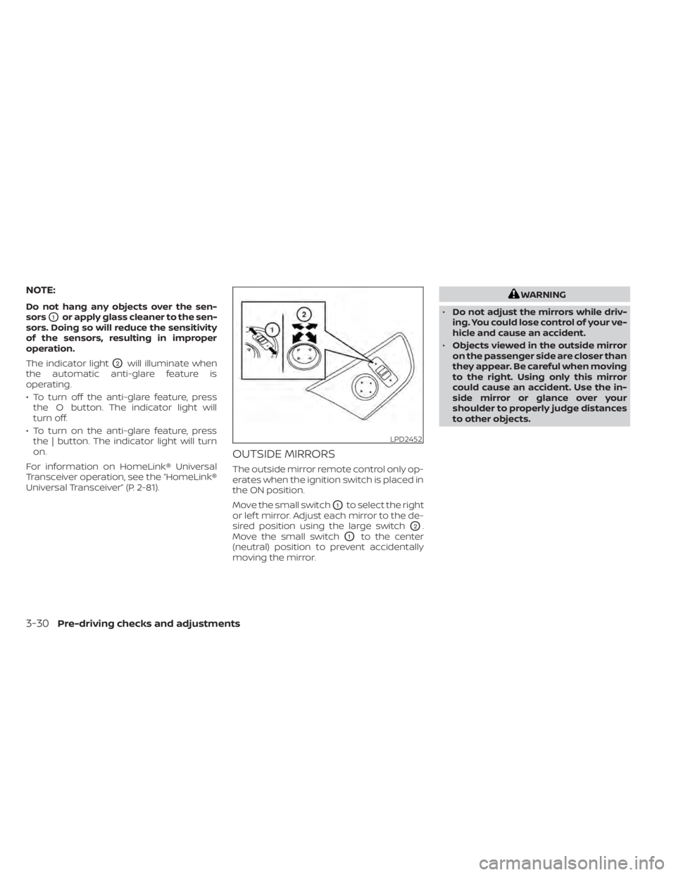
The indicator light
O2will illuminate when
the automatic anti-glare feature is
operating.
• To turn off the anti-glare feature, press the O button. The indicator light will
turn off.
• To turn on the anti-glare feature, press the | button. The indicator light will turn
on.
For information on HomeLink® Universal
Transceiver operation, see the “HomeLink®
Universal Transceiver” (P. 2-81).
OUTSIDE MIRRORS
The outside mirror remote control only op-
erates when the ignition switch is placed in
the ON position.
Move the small switch
O1to select the right
or lef t mirror. Adjust each mirror to the de-
sired position using the large switch
O2.
Move the small switch
O1to the center
(neutral) position to prevent accidentally
moving the mirror.
WARNING
• Do not adjust the mirrors while driv-
ing. You could lose control of your ve-
hicle and cause an accident.
• Objects viewed in the outside mirror
on the passenger side are closer than
they appear. Be careful when moving
to the right. Using only this mirror
could cause an accident. Use the in-
side mirror or glance over your
shoulder to properly judge distances
to other objects.
LPD2452
3-30Pre-driving checks and adjustments
Page 208 of 644
Once step 4 is completed, every time the
ignition is switched from ON to OFF, the
memory positions of the driver’s seat and
outside mirror (if so equipped) are linked to
the Intelligent Key.
Follow the same procedure if you want
to link the 2nd, 3rd or 4th Intelligent Key.
NOTE:
If new memory positions are set prior to
turning the ignition from ON to OFF, the
previously linked memory positions for
the respective key will be overwritten by
new positions.
Recalling Intelligent Key memory
positions
If the “Key-Linked Settings” are enabled in
the vehicle information display for that par-
ticular key, every time you enter the vehicle
the driver’s seat and outside mirrors (if so
equipped) will automatically move to the
driver’s last position of the respective Intel-
ligent Key.
NOTE:
The key-linked memory positions can be
different from the positions stored in the
memory switch (1 or 2).
MEMORY STORAGE FUNCTION
(switch)
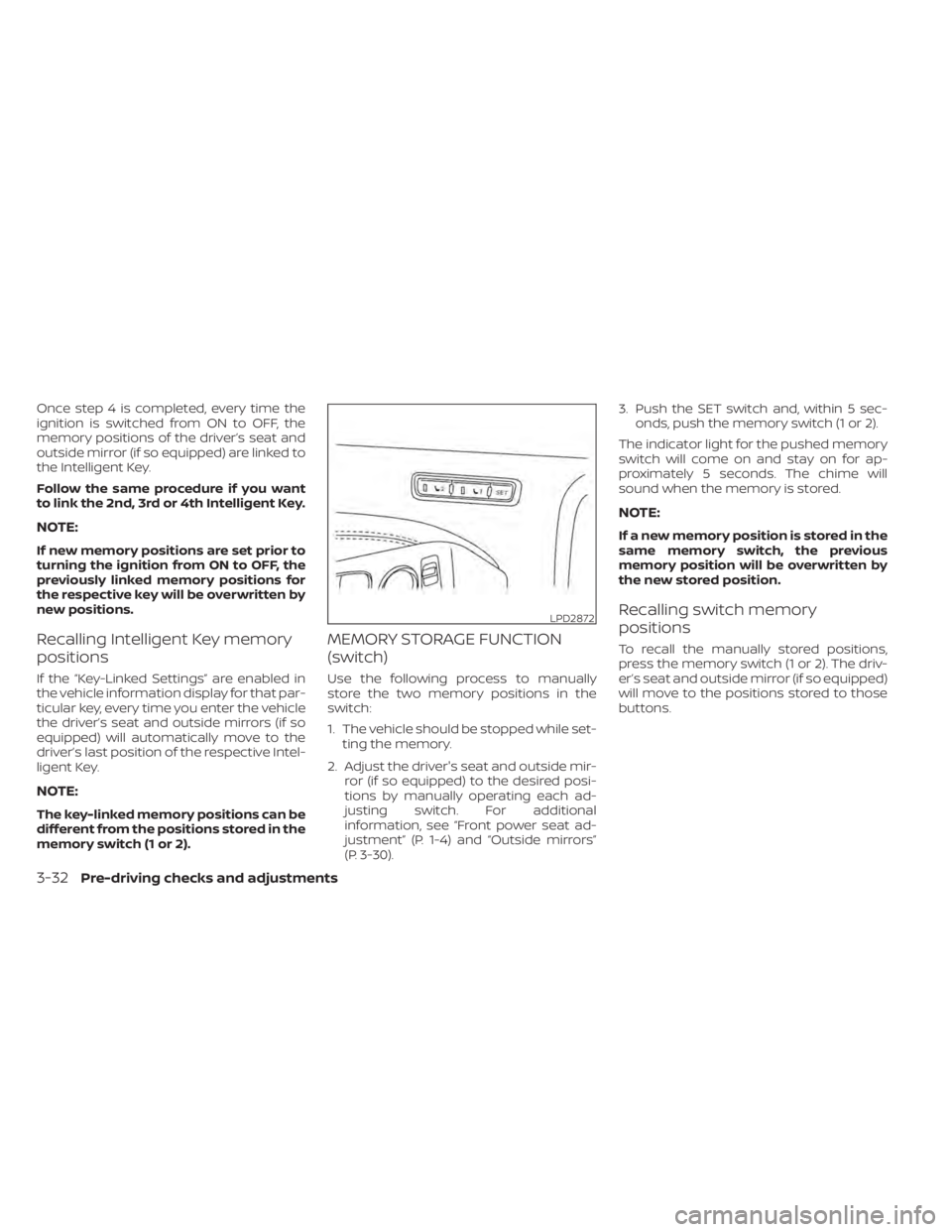
Use the following process to manually
store the two memory positions in the
switch:
1. The vehicle should be stopped while set-ting the memory.
2. Adjust the driver's seat and outside mir- ror (if so equipped) to the desired posi-
tions by manually operating each ad-
justing switch. For additional
information, see “Front power seat ad-
justment” (P. 1-4) and “Outside mirrors”
(P. 3-30). 3. Push the SET switch and, within 5 sec-
onds, push the memory switch (1 or 2).
The indicator light for the pushed memory
switch will come on and stay on for ap-
proximately 5 seconds. The chime will
sound when the memory is stored.
NOTE:
If a new memory position is stored in the
same memory switch, the previous
memory position will be overwritten by
the new stored position.
Recalling switch memory
positions
To recall the manually stored positions,
press the memory switch (1 or 2). The driv-
er’s seat and outside mirror (if so equipped)
will move to the positions stored to those
buttons.
LPD2872
3-32Pre-driving checks and adjustments
Page 216 of 644
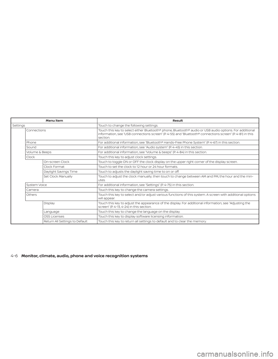
Menu itemResult
Settings Touch to change the following settings.
Connections Touch this key to select either Bluetooth® phone, Bluetooth® audio or USB audio options. For additional
information, see “USB connections screen” (P. 4-55) and “Bluetooth® connections screen” (P. 4-81) in this
section.
Phone For additional information, see “Bluetooth® Hands-Free Phone System” (P. 4-67) in this section.
Sound For additional information, see “Audio system” (P. 4-45) in this section.
Volume & Beeps For additional information, see “Volume & beeps” (P. 4-84) in this section.
Clock Touch this key to adjust clock settings.
On-screen Clock Touch to toggle ON or OFF the clock display on the upper right corner of the display screen.
Clock Format Touch to set the clock to 12 hour or 24 hour formats.
Daylight Savings Time Touch to adjusts the daylight saving time to on or off.
Set Clock Manually Touch to adjust the clock manually; then touch to change between AM and PM, the hour and the min-
utes.
System Voice For additional information, see “Settings” (P. 4-75) in this section.
Camera Touch this key to change the camera settings.
Others Touch this key to select and/or adjust various functions of this system. A screen with additional options
will appear.
Display Touch this key to adjust the appearance of the display. For additional information, see “Adjusting the
screen” (P. 4-13, 4-24) in this section.
Language Touch this key to change the language on the display.
OSS Licenses Touch this key to display sof tware licensing information.
Return All Settings to Default Touch this key to return all settings to default and to clear the memory.
4-6Monitor, climate, audio, phone and voice recognition systems
Page 224 of 644
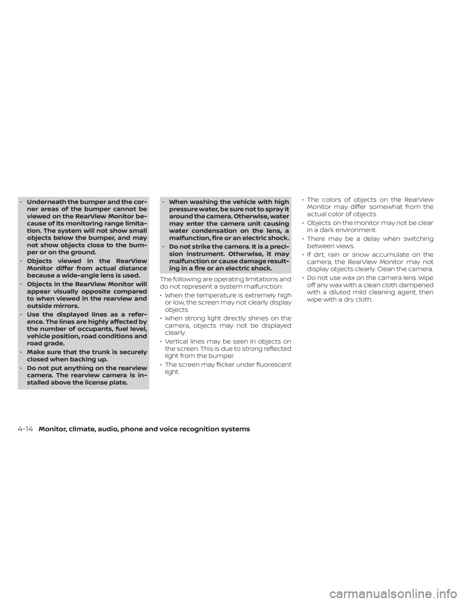
•Underneath the bumper and the cor-
ner areas of the bumper cannot be
viewed on the RearView Monitor be-
cause of its monitoring range limita-
tion. The system will not show small
objects below the bumper, and may
not show objects close to the bum-
per or on the ground.
• Objects viewed in the RearView
Monitor differ from actual distance
because a wide-angle lens is used.
• Objects in the RearView Monitor will
appear visually opposite compared
to when viewed in the rearview and
outside mirrors.
• Use the displayed lines as a refer-
ence. The lines are highly affected by
the number of occupants, fuel level,
vehicle position, road conditions and
road grade.
• Make sure that the trunk is securely
closed when backing up.
• Do not put anything on the rearview
camera. The rearview camera is in-
stalled above the license plate. •
When washing the vehicle with high
pressure water, be sure not to spray it
around the camera. Otherwise, water
may enter the camera unit causing
water condensation on the lens, a
malfunction, fire or an electric shock.
• Do not strike the camera. It is a preci-
sion instrument. Otherwise, it may
malfunction or cause damage result-
ing in a fire or an electric shock.
The following are operating limitations and
do not represent a system malfunction:
• When the temperature is extremely high or low, the screen may not clearly display
objects.
• When strong light directly shines on the camera, objects may not be displayed
clearly.
• Vertical lines may be seen in objects on the screen. This is due to strong reflected
light from the bumper.
• The screen may flicker under fluorescent light. • The colors of objects on the RearView
Monitor may differ somewhat from the
actual color of objects.
• Objects on the monitor may not be clear in a dark environment.
• There may be a delay when switching between views.
• If dirt, rain or snow accumulate on the camera, the RearView Monitor may not
display objects clearly. Clean the camera.
• Do not use wax on the camera lens. Wipe off any wax with a clean cloth dampened
with a diluted mild cleaning agent, then
wipe with a dry cloth.
4-14Monitor, climate, audio, phone and voice recognition systems
Page 228 of 644

The screen displayed on the Intelligent
Around View Monitor will automatically re-
turn to the previous screen 3 minutes af ter
the CAMERA button has been pressed with
the shif t lever in a position other than the R
(Reverse) position.
Available views
WARNING
• The distance guide lines and the ve-
hicle width lines should be used as a
reference only when the vehicle is on
a paved, level surface. The apparent
distance viewed on the monitor may
be different than the actual distance
between the vehicle and displayed
objects.
• Use the displayed lines and the
bird’s-eye view as a reference. The
lines and the bird’s-eye view are
greatly affected by the number of oc-
cupants, cargo, fuel level, vehicle po-
sition, road condition and road
grade.
• If the tires are replaced with different
sized tires, the predicted course lines
and the bird's-eye view may be dis-
played incorrectly. •
When driving the vehicle up a hill, ob-
jects viewed in the monitor are fur-
ther than they appear. When driving
the vehicle down a hill, objects
viewed in the monitor are closer than
they appear.
• Objects in the rear view will appear
visually opposite compared to when
viewed in the monitor and outside
mirrors.
• Use the mirrors or actually look to
properly judge distances to other
objects.
• On a snow-covered or slippery road,
there may be a difference between
the predicted course lines and the
actual course line.
• The vehicle width and predicted
course lines are wider than the actual
width and course.
• The displayed lines will appear
slightly off to the right, because the
rearview camera is not installed in
the rear center of the vehicle.
Front and rear view
Guiding lines that indicate the approximate
vehicle width and distance to objects with
reference to the vehicle body line
OAare
displayed on the monitor.
Distance guide lines:
Indicate distances from the vehicle body:
• Red line
O1: approximately 1.5 f t (0.5 m)
• Yellow line
O2: approximately 3 f t (1 m)
• Green line
O3: approximately 7 f t (2 m)
• Green line
O4: approximately 10 f t (3 m) (if
so equipped)
SAA1840
Front view
4-18Monitor, climate, audio, phone and voice recognition systems
Page 230 of 644

Af ter the ignition switched is placed in the
ON position, the non-viewable area
O2is
highlighted in yellow for 3 seconds af ter the
birds-eye view is displayed.
In addition, the non-viewable corners are
displayed in red and will blink for the first 3
seconds
O3to remind the driver to be
cautious.
WARNING
• Objects in the bird's-eye view will ap-
pear further than the actual distance.
• Tall objects, such as a curb or vehicle,
may be misaligned or not displayed
at the seam of the views.
• Objects that are above the camera
cannot be displayed.
• The view of the bird's-eye view may
be misaligned when the camera po-
sition alters.
• A line on the ground may be mis-
aligned and is not seen as being
straight at the seam of the views. The
misalignment will increase as the
line proceeds away from the vehicle.
Front-side view
Guiding lines
Guiding lines that indicate the approximate
width and the front end of the vehicle are
displayed on the monitor.
The front-of-vehicle line
O1shows the front
part of the vehicle.
The side-of-vehicle line
O2shows the ap-
proximate vehicle width including the out-
side mirrors.
The extensions
O3of both the frontO1and
side
O2lines are shown with a green dotted
line.
DIFFERENCE BETWEEN PREDICTED
AND ACTUAL DISTANCES
The displayed guidelines and their loca-
tions on the ground are for approximate
reference only. Objects on uphill or downhill
surfaces or projecting objects will be actu-
ally located at distances different from
those displayed in the monitor relative to
the guidelines (refer to illustrations). When
in doubt, turn around and view the objects
as you are backing up, or park and exit the
vehicle to view the positioning of objects
behind the vehicle.
LHA2652
4-20Monitor, climate, audio, phone and voice recognition systems