2023 HYUNDAI SONATA fuel cap
[x] Cancel search: fuel capPage 484 of 555
Maintenance
8-14
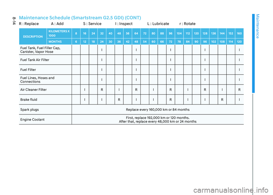
Maintenance Schedule (Smartstream G2.5 GDI) (CONT)R : Replace A : Add S : Service I : Inspect L : Lubricate r : RotateDESCRIPTIONKILOMETERS X 1000
8 16 24 32 40 48 56 64 72 80 88 96 104 112 120 128 136 144 152 160
MONTHS 6 12 18 24 30 36 42 48 54 60 66 72 78 84 90 96 102 108 114 120Fuel Tank, Fuel Filler Cap,
Canister, Vapor Hose I I I I I
Fuel Tank Air Filter I I I I I Fuel Filter I I I I I
Fuel Lines, Hoses and Connections I I I I I
Air Cleaner Filter I R I R I R I R I R Brake fluid I I R I I R I I R ISpark plugs Replace every 160,000 km or 84 months
Engine Coolant First, replace 192,000 km or 120 months.
After that, replace every 48,000 km or 24 months
Page 488 of 555
Maintenance
8-18
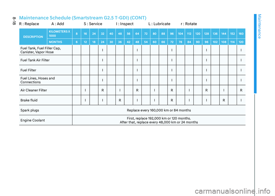
Maintenance Schedule (Smartstream G2.5 T-GDI) (CONT)R : Replace A : Add S : Service I : Inspect L : Lubricate r : RotateDESCRIPTIONKILOMETERS X 1000
8 16 24 32 40 48 56 64 72 80 88 96 104 112 120 128 136 144 152 160
MONTHS 6 12 18 24 30 36 42 48 54 60 66 72 78 84 90 96 102 108 114 120Fuel Tank, Fuel Filler Cap,
Canister, Vapor Hose I I I I I
Fuel Tank Air Filter I I I I I Fuel Filter I I I I I
Fuel Lines, Hoses and Connections I I I I I
Air Cleaner Filter I R I R I R I R I R Brake fluid I I R I I R I I R ISpark plugs Replace every 160,000 km or 84 months
Engine Coolant First, replace 192,000 km or 120 months.
After that, replace every 48,000 km or 24 months
Page 490 of 555
Maintenance
8-20
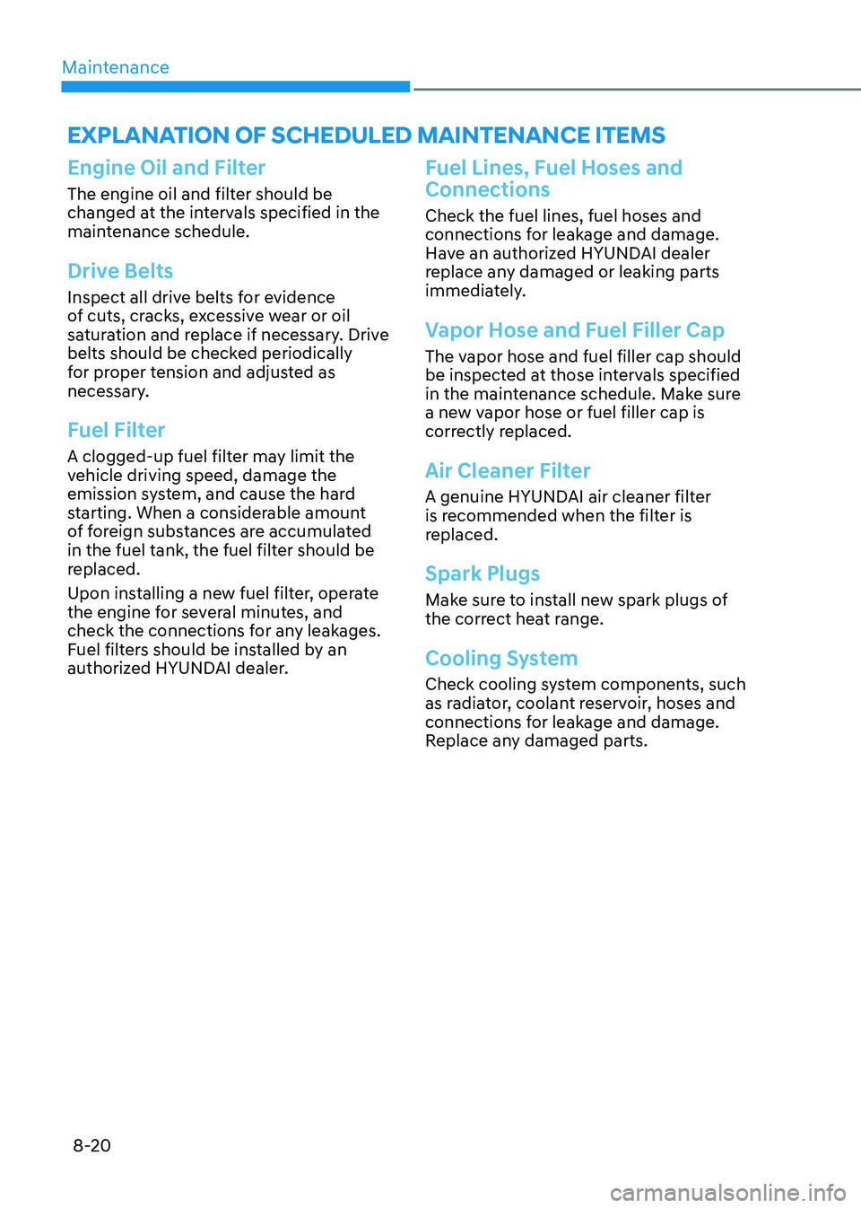
Engine Oil and Filter
The engine oil and filter should be
changed at the intervals specified in the
maintenance schedule.
Drive Belts
Inspect all drive belts for evidence
of cuts, cracks, excessive wear or oil
saturation and replace if necessary. Drive
belts should be checked periodically
for proper tension and adjusted as
necessary.
Fuel Filter
A clogged-up fuel filter may limit the
vehicle driving speed, damage the
emission system, and cause the hard
starting. When a considerable amount
of foreign substances are accumulated
in the fuel tank, the fuel filter should be
replaced.
Upon installing a new fuel filter, operate
the engine for several minutes, and
check the connections for any leakages.
Fuel filters should be installed by an
authorized HYUNDAI dealer.
Fuel Lines, Fuel Hoses and Connections
Check the fuel lines, fuel hoses and
connections for leakage and damage.
Have an authorized HYUNDAI dealer
replace any damaged or leaking parts
immediately.
Vapor Hose and Fuel Filler Cap
The vapor hose and fuel filler cap should
be inspected at those intervals specified
in the maintenance schedule. Make sure
a new vapor hose or fuel filler cap is
correctly replaced.
Air Cleaner Filter
A genuine HYUNDAI air cleaner filter
is recommended when the filter is
replaced.
Spark Plugs
Make sure to install new spark plugs of
the correct heat range.
Cooling System
Check cooling system components, such
as radiator, coolant reservoir, hoses and
connections for leakage and damage.
Replace any damaged parts.
ExpLanation of SCHEDULED maintEnanCE itEmS
Page 509 of 555
08
8-39
WARNING
Recommended pressures must be
maintained for the best ride, vehicle
handling, and minimum tire wear.
Over-inflation or under-inflation can
reduce tire life, adversely affect vehicle
handling, and lead to sudden tire failure
that could result in loss of vehicle
control resulting in an accident.
Severe under-inflation can lead to
severe heat build-up, causing blowouts,
tread separation and other tire failures
that can result in the loss of vehicle
control resulting in an accident. This
risk is much higher on hot days and
when driving for long periods at high speeds.
CAUTION
• Under-inflation results in excessive
wear, poor handling and reduced
fuel economy. Wheel deformation
is also possible. Keep your tire
pressures at the proper levels. If a
tire frequently needs refilling, have it
checked by an authorized HYUNDAI
dealer.
• Over-inflation produces a harsh ride,
excessive wear at the center of the
tire tread, and a greater possibility of
damage from road hazards.
Check Tire Inflation Pressure
Check your tires, including the spare tire,
once a month or more.
How to check
Use a good quality tire pressure gauge
to check tire pressure. You can not tell
if your tires are properly inflated simply
by looking at them. Radial tires may look
properly inflated when they are under-
inflated.
Remove the valve cap from the tire valve
stem. Press the tire gauge firmly onto the
valve to get a pressure measurement.
If the cold tire inflation pressure
matches the recommended pressure
on the tire label located on the driver’s
side center pillar or in this manual. No
further adjustment is necessary. If the
pressure is low, add air until you reach
the recommended pressure. Make sure
to put the valve caps back on the valve
stems. Without the valve cap, dirt or
moisture could get into the valve core
and cause air leakage. If a valve cap is
missing, install a new one as soon as possible.
If you overfill the tire, release air by
pushing on the metal stem in the
center of the tire valve. Recheck the tire
pressure with the tire gauge. Be sure
to put the valve caps back on the valve
stems. Without the valve cap, dirt or
moisture could get into the valve core
and cause air leakage. If a valve cap is
missing, install a new one as soon as possible.
A cold tire means the vehicle has been
sitting for 3 hours and driven for less
than 1.6 km (1 mile) in that 3 hour period.
Allow the tire to cool before measuring
the inflation pressure. Always be sure
the tire is cold before inflating to the
recommended pressure.
Page 515 of 555
08
8-45
WARNING
The traction grade assigned to this tire
is based on straight-ahead braking
traction tests, and does not include
acceleration, cornering, hydroplaning,
or peak traction characteristics.
Temperature A, B & C
The temperature grades are A (the
highest), B and C representing the tire’s
resistance to the generation of heat
and its ability to dissipate heat when
tested under controlled conditions on a
specified indoor laboratory test wheel.
Sustained high temperature can cause
the material of the tire to degenerate
and reduce tire life, and excessive
temperature can lead to sudden tire
failure.
WARNING
The temperature grade for this tire is
established for a tire that is properly
inflated and not overloaded. Excessive
speed, under-inflation, over-inflation,
or excessive loading, either separately
or in combination, can cause heat build-
up and possible sudden tire failure.
This may cause loss of vehicle control
resulting in an accident.
Tire Terminology and Definitions
Air Pressure
The amount of air inside the tire pressing
outward on the tire. Air pressure is
expressed in kilopascal (kPa) or pounds
per square inch (psi).
Accessory Weight
This means the combined weight of
optional accessories. Some examples
of optional accessories are automatic
transmission, power seats, and air conditioning.
Aspect Ratio
The relationship of a tire’s height to its width. Belt
A rubber coated layer of cords that is
located between the plies and the tread.
Cords may be made from steel or other
reinforcing materials. Bead
The tire bead contains steel wires
wrapped by steel cords that hold the tire
onto the rim.
Bias Ply Tire
A pneumatic tire in which the plies are
laid at alternate angles less than 90
degrees to the centerline of the tread.
Cold Tire Pressure
The amount of air pressure in a tire,
measured in kilopascals (kPa) or pounds
per square inch (psi) before a tire has
built up heat from driving.
Curb Weight
This means the weight of a motor vehicle
with standard and optional equipment
including the maximum capacity of fuel,
oil and coolant, but without passengers
and cargo.
Page 541 of 555
08
8-71
1. Crankcase Emission Control System
The positive crankcase ventilation system
is employed to prevent air pollution
caused by blow-by gases being emitted
from the crankcase. This system supplies
fresh filtered air to the crankcase through
the air intake hose. Inside the crankcase,
the fresh air mixes with blow-by gases,
which then pass through the PCV valve
into the induction system.
2. Evaporative Emission Control System Including Onboard
Refueling Vapor Recovery
(ORVR)
The Evaporative Emission Control System
is designed to prevent fuel vapors from
escaping into the atmosphere. The
ORVR system is designed to allow the
vapors from the fuel tank to be loaded
into a canister while refueling at the gas
station, preventing the escape of fuel
vapors into the atmosphere.
Canister
Fuel vapors generated inside the fuel
tank are absorbed and stored in the
onboard canister. When the engine is
running, the fuel vapors absorbed in the
canister are drawn into the surge tank
through the purge control solenoid valve.
Purge Control Solenoid Valve (PCSV)
The purge control solenoid valve
is controlled by the Engine Control
Module (ECM); when the engine coolant
temperature is low during idling, the
PCSV closes so that evaporated fuel
is not taken into the engine. After the
engine warms-up during ordinary
driving, the PCSV opens to introduce
evaporated fuel to the engine.
3. Exhaust Emission Control System
The Exhaust Emission Control System is
a highly effective system which controls
exhaust emissions while maintaining
good vehicle performance.
When the engine starts or fails to start,
excessive attempts to restart the engine
may cause damage to the emission
system.
Engine exhaust (carbon monoxide)
precautions • Carbon monoxide can be present
with other exhaust fumes. If you smell
exhaust fumes of any kind in your
vehicle, drive with all the windows
fully open. Have your vehicle checked
and repaired immediately.
WARNING
Engine exhaust gases contain carbon
monoxide (CO). Though colorless and
odorless, it is dangerous and could be
lethal if inhaled. Follow the instructions
on this page to avoid CO poisoning.