2023 HYUNDAI SONATA Fuel door
[x] Cancel search: Fuel doorPage 330 of 555
06
6-43
The Launch Control system controls the
vehicle to reduce wheel spin or slip on a
hard acceleration from a standing start.
Launch control operation and
release
Prerequisite for activation
The Launch Control gets ready to
be activated, when the following
prerequisites are satisfied. •
All doors, hood and trunk are closed.
• The driver’s seat belt is fastened.
• If the engine temperature is
overheated, cooling down it before
using the launch control.
• If the engine temperature is low,
warming up the engine.
• The vehicle is at a complete stop.
Then align the steering wheel straight.
• Release the parking brake by pressing
the EPB switch and if the AUTO HOLD
function is working, please turn off
the function by releasing the AUTO
HOLD button.
CAUTION
• The Launch Control system is
intended for use at a closed race
track and not intended for use on
public roads. It will not compensate
for driver’s who are inexperienced or
lack familiarity with the race track.
• The Launch performance may be
varied by fuel, environment, tire and
load condition.
• We recommend you use the function
after breaking in your vehicle and
constant use of Launch Control can
put enormous stress on the vehicle
resulting in premature wear of
related components. To Ready Launch Control
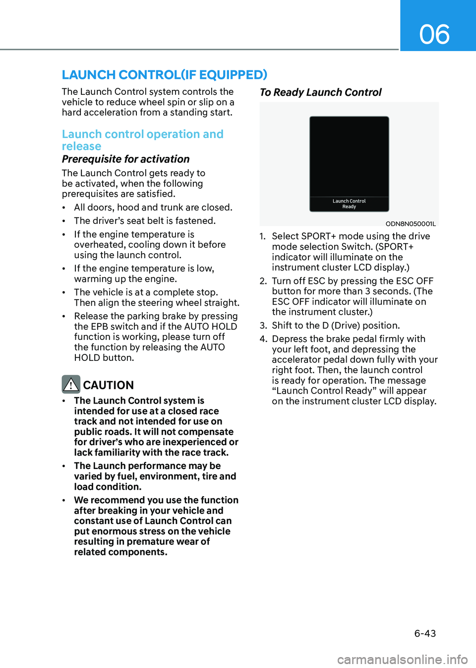
ODN8N050001L
1. Select SPORT+ mode using the drive mode selection Switch. (SPORT+
indicator will illuminate on the
instrument cluster LCD display.)
2. Turn off ESC by pressing the ESC OFF button for more than 3 seconds. (The
ESC OFF indicator will illuminate on
the instrument cluster.)
3. Shift to the D (Drive) position.
4. Depress the brake pedal firmly with
your left foot, and depressing the
accelerator pedal down fully with your
right foot. Then, the launch control
is ready for operation. The message
“Launch Control Ready” will appear
on the instrument cluster LCD display.
launch control(if equippeD)
Page 443 of 555
While Driving
6-156
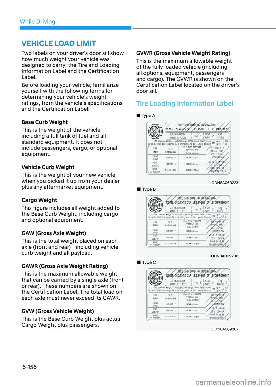
Two labels on your driver's door sill show
how much weight your vehicle was
designed to carry: the Tire and Loading
Information Label and the Certification Label.
Before loading your vehicle, familiarize
yourself with the following terms for
determining your vehicle’s weight
ratings, from the vehicle's specifications
and the Certification Label:
Base Curb Weight
This is the weight of the vehicle
including a full tank of fuel and all
standard equipment. It does not
include passengers, cargo, or optional
equipment.
Vehicle Curb Weight
This is the weight of your new vehicle
when you picked it up from your dealer
plus any aftermarket equipment.
Cargo Weight
This figure includes all weight added to
the Base Curb Weight, including cargo
and optional equipment.
GAW (Gross Axle Weight)
This is the total weight placed on each
axle (front and rear) - including vehicle
curb weight and all payload.
GAWR (Gross Axle Weight Rating)
This is the maximum allowable weight
that can be carried by a single axle (front
or rear). These numbers are shown on
the Certification Label. The total load on
each axle must never exceed its GAWR.
GVW (Gross Vehicle Weight)
This is the Base Curb Weight plus actual
Cargo Weight plus passengers.
GVWR (Gross Vehicle Weight Rating)
This is the maximum allowable weight
of the fully loaded vehicle (including
all options, equipment, passengers
and cargo). The GVWR is shown on the
Certification Label located on the driver’s door sill.
Tire Loading Information Label
ODN8A060223
„
„Type A
„„Type B
ODN8A069206
„„Type C
ODN8A069207
vehicle loAD liMit
Page 447 of 555
While Driving
6-160
Certification label
The certification label is located on the
driver’s door sill at the center pillar and
shows the maximum allowable weight of
the fully loaded vehicle. This is called the
GVWR (Gross Vehicle Weight Rating). The
GVWR includes the weight of the vehicle,
all occupants, fuel and cargo.
This label also tells you the maximum
weight that can be supported by the
front and rear axles, called Gross Axle
Weight Rating (GAWR).
The total weight of the vehicle, including
all occupants, accessories, cargo, and
trailer tongue load must not exceed the
Gross Vehicle Weight Rating (GVWR) or
the Gross Axle Weight Rating (GAWR).
To find out the actual loads on your front
and rear axles, you need to go to a weigh
station and weigh your vehicle. Be sure
to spread out your load equally on both
sides of the centerline.
WARNING
Overloading • Never exceed the GVWR for your
vehicle, the GAWR for either the front
or rear axle and vehicle capacity
weight. Exceeding these ratings
can affect your vehicle’s handling
and braking ability, and cause an
accident.
• Do not overload your vehicle.
Overloading your vehicle can cause
heat buildup in your vehicle’s tires
and possible tire failure, increased
stopping distances and poor vehicle
handling-all of which may result in a
crash.
NOTICE
Overloading your vehicle may cause
damage. Repairs would not be covered
by your warranty. Do not overload your
vehicle.
WARNING
If you carry items inside your vehicle
(e.g., suitcases, tools, packages, or
anything else), they are moving as fast
as the vehicle. If you have to stop or
turn quickly, or if there is a crash, the
items will keep going and can cause
an injury if they strike the driver or a
passenger. • Put items in the cargo area of your
vehicle. Try to spread the weight
evenly.
• Do not stack items, like suitcases,
inside the vehicle above the tops of
the seats.
• Do not leave an unsecured child
restraint in your vehicle.
• When you carry something inside the
vehicle, secure it.
Page 476 of 555
Maintenance
8-6
WARNING
Performing maintenance work on a
vehicle can be dangerous. If you lack
sufficient knowledge and experience or
the proper tools and equipment to do
the work, have it done by an authorized
HYUNDAI dealer.
ALWAYS follow these precautions for
performing maintenance work: • Park your vehicle on level ground,
move the shift button into the P
(Park) position, place the ignition
switch in the LOCK/OFF position.
• Block the tires (front and back) to
prevent the vehicle from moving.
Remove loose clothing or jewelry
that can become entangled in
moving parts.
• If you must run the engine during
maintenance, do so out doors or in
an area with plenty of ventilation.
• Keep flames, sparks, or smoking
materials away from the battery and
fuel-related parts. The following lists are vehicle checks and
inspections that should be performed
by the owner or an authorized HYUNDAI
dealer at the frequencies indicated to
help ensure safe, dependable operation
of your vehicle.
Any adverse conditions should be
brought to the attention of your dealer as soon as possible.
These Owner Maintenance vehicle
checks are generally not covered by
warranties and you may be charged for
labor, parts and lubricants used.
Owner Maintenance Schedule
When you stop for fuel: •
Check the coolant level in the engine
coolant reservoir.
• Check the windshield washer fluid
level.
• Check the for low or under-inflated
tires.
WARNING
Be careful when checking your engine
coolant level when the engine is hot.
This may result in coolant being blown
out of the opening and cause serious
burns and other injuries.
ownEr maintEnanCE
Page 515 of 555
08
8-45
WARNING
The traction grade assigned to this tire
is based on straight-ahead braking
traction tests, and does not include
acceleration, cornering, hydroplaning,
or peak traction characteristics.
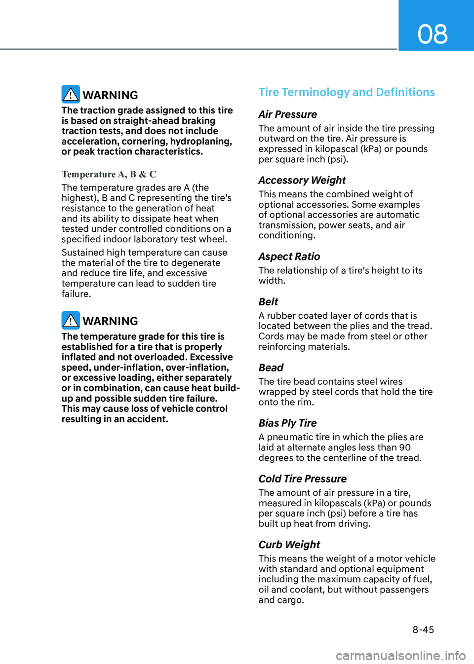
Temperature A, B & C
The temperature grades are A (the
highest), B and C representing the tire’s
resistance to the generation of heat
and its ability to dissipate heat when
tested under controlled conditions on a
specified indoor laboratory test wheel.
Sustained high temperature can cause
the material of the tire to degenerate
and reduce tire life, and excessive
temperature can lead to sudden tire
failure.
WARNING
The temperature grade for this tire is
established for a tire that is properly
inflated and not overloaded. Excessive
speed, under-inflation, over-inflation,
or excessive loading, either separately
or in combination, can cause heat build-
up and possible sudden tire failure.
This may cause loss of vehicle control
resulting in an accident.
Tire Terminology and Definitions
Air Pressure
The amount of air inside the tire pressing
outward on the tire. Air pressure is
expressed in kilopascal (kPa) or pounds
per square inch (psi).
Accessory Weight
This means the combined weight of
optional accessories. Some examples
of optional accessories are automatic
transmission, power seats, and air conditioning.
Aspect Ratio
The relationship of a tire’s height to its width. Belt
A rubber coated layer of cords that is
located between the plies and the tread.
Cords may be made from steel or other
reinforcing materials. Bead
The tire bead contains steel wires
wrapped by steel cords that hold the tire
onto the rim.
Bias Ply Tire
A pneumatic tire in which the plies are
laid at alternate angles less than 90
degrees to the centerline of the tread.
Cold Tire Pressure
The amount of air pressure in a tire,
measured in kilopascals (kPa) or pounds
per square inch (psi) before a tire has
built up heat from driving.
Curb Weight
This means the weight of a motor vehicle
with standard and optional equipment
including the maximum capacity of fuel,
oil and coolant, but without passengers
and cargo.
Page 527 of 555
08
8-57
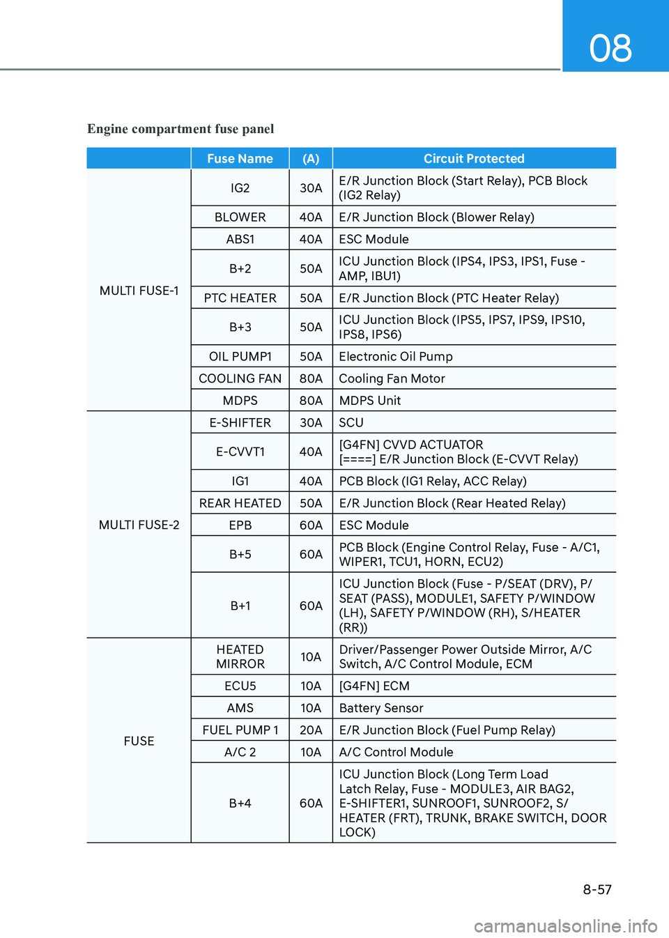
Engine compartment fuse panel
Fuse Name (A) Circuit Protected
MULTI FUSE-1 IG2 30A
E/R Junction Block (Start Relay), PCB Block
(IG2 Relay)
BLOWER 40A E/R Junction Block (Blower Relay) ABS1 40A ESC Module
B+2 50A ICU Junction Block (IPS4, IPS3, IPS1, Fuse -
AMP, IBU1)
PTC HEATER 50A E/R Junction Block (PTC Heater Relay)
B+3 50A ICU Junction Block (IPS5, IPS7, IPS9, IPS10, IPS8, IPS6)
OIL PUMP1 50A Electronic Oil Pump
COOLING FAN 80A Cooling Fan Motor MDPS 80A MDPS Unit
MULTI FUSE-2 E-SHIFTER 30A SCU
E-CVVT1 40A [G4FN] CVVD ACTUATOR
[====] E/R Junction Block (E-CVVT Relay)
IG1 40A PCB Block (IG1 Relay, ACC Relay)
REAR HEATED 50A E/R Junction Block (Rear Heated Relay)
EPB 60A ESC Module
B+5 60A PCB Block (Engine Control Relay, Fuse - A/C1,
WIPER1, TCU1, HORN, ECU2)
B+1 60A ICU Junction Block (Fuse - P/SEAT (DRV), P/
SEAT (PASS), MODULE1, SAFETY P/WINDOW
(LH), SAFETY P/WINDOW (RH), S/HEATER
(RR))
FUSE HEATED
MIRROR 10A Driver/Passenger Power Outside Mirror, A/C
Switch, A/C Control Module, ECM
ECU5 10A [G4FN] ECM AMS 10A Battery Sensor
FUEL PUMP 1 20A E/R Junction Block (Fuel Pump Relay) A/C 2 10A A/C Control Module
B+4 60A ICU Junction Block (Long Term Load
Latch Relay, Fuse - MODULE3, AIR BAG2,
E-SHIFTER1, SUNROOF1, SUNROOF2, S/
HEATER (FRT), TRUNK, BRAKE SWITCH, DOOR
LOCK)
Page 536 of 555
Maintenance
8-66
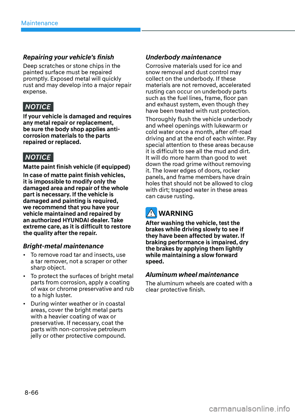
Repairing your vehicle’s finish
Deep scratches or stone chips in the
painted surface must be repaired
promptly. Exposed metal will quickly
rust and may develop into a major repair
expense.
NOTICE
If your vehicle is damaged and requires
any metal repair or replacement,
be sure the body shop applies anti-
corrosion materials to the parts
repaired or replaced.
NOTICE
Matte paint finish vehicle (if equipped)
In case of matte paint finish vehicles,
it is impossible to modify only the
damaged area and repair of the whole
part is necessary. If the vehicle is
damaged and painting is required,
we recommend that you have your
vehicle maintained and repaired by
an authorized HYUNDAI dealer. Take
extreme care, as it is difficult to restore
the quality after the repair.
Bright-metal maintenance • To remove road tar and insects, use
a tar remover, not a scraper or other sharp object.
• To protect the surfaces of bright metal
parts from corrosion, apply a coating
of wax or chrome preservative and rub
to a high luster.
• During winter weather or in coastal
areas, cover the bright metal parts
with a heavier coating of wax or
preservative. If necessary, coat the
parts with non-corrosive petroleum
jelly or other protective compound. Underbody maintenance
Corrosive materials used for ice and
snow removal and dust control may
collect on the underbody. If these
materials are not removed, accelerated
rusting can occur on underbody parts
such as the fuel lines, frame, floor pan
and exhaust system, even though they
have been treated with rust protection.
Thoroughly flush the vehicle underbody
and wheel openings with lukewarm or
cold water once a month, after off-road
driving and at the end of each winter. Pay
special attention to these areas because
it is difficult to see all the mud and dirt.
It will do more harm than good to wet
down the road grime without removing
it. The lower edges of doors, rocker
panels, and frame members have drain
holes that should not be allowed to clog
with dirt; trapped water in these areas
can cause rusting.
WARNING
After washing the vehicle, test the
brakes while driving slowly to see if
they have been affected by water. If
braking performance is impaired, dry
the brakes by applying them lightly
while maintaining a slow forward speed.
Aluminum wheel maintenance
The aluminum wheels are coated with a
clear protective finish.
Page 547 of 555
I
I-5
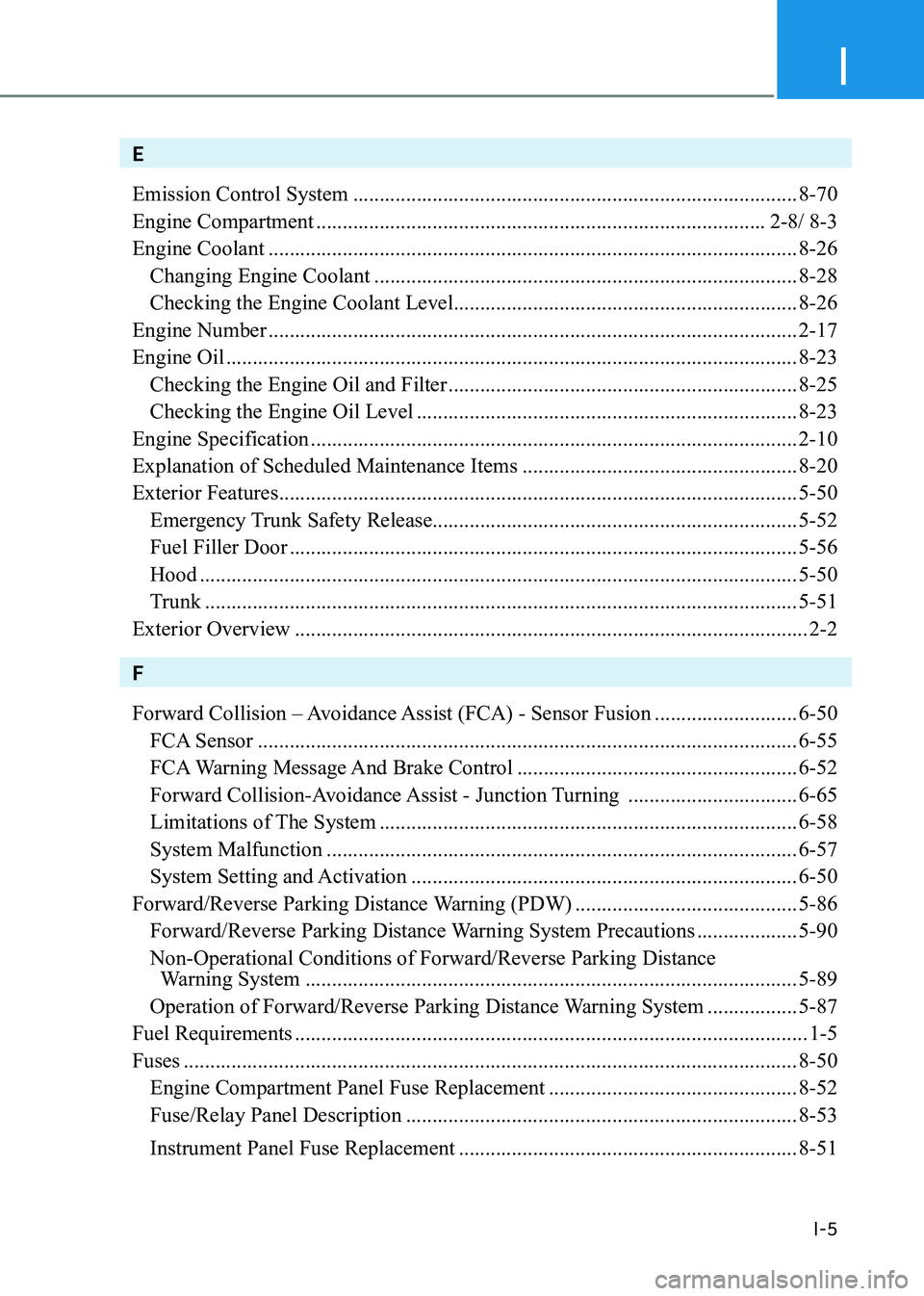
E Emission Control System .................................................................................... 8-70
Engine Compartment ..................................................................................... 2-8/ 8-3
Engine Coolant .................................................................................................... 8-26
Changing Engine Coolant ................................................................................ 8-28
Checking the Engine Coolant Level ................................................................. 8-26
Engine Number .................................................................................................... 2-17
Engine Oil ............................................................................................................ 8-23
Checking the Engine Oil and Filter .................................................................. 8-25
Checking the Engine Oil Level ........................................................................ 8-23
Engine Specification ............................................................................................ 2-10
Explanation of Scheduled Maintenance Items ....................................................8-20
Exterior Features .................................................................................................. 5-50
Emergency Trunk Safety Release..................................................................... 5-52
Fuel Filler Door ................................................................................................ 5-56
Hood ................................................................................................................. 5-50
Trunk ................................................................................................................ 5-51
Exterior Overview ................................................................................................. 2-2
F
Forward Collision – Avoidance Assist (FCA) - Sensor Fusion ...........................6-50
FCA Sensor ...................................................................................................... 6-55
FCA Warning Message And Brake Control .....................................................6-52
Forward Collision-Avoidance Assist - Junction Turning ................................6-65
Limitations of The System ............................................................................... 6-58
System Malfunction ......................................................................................... 6-57
System Setting and Activation ......................................................................... 6-50
Forward/Reverse Parking Distance Warning (PDW) ..........................................5-86
Forward/Reverse Parking Distance Warning System Precautions ...................5-90
Non-Operational Conditions of Forward/Reverse Parking Distance
Warning System ............................................................................................. 5-89
Operation of Forward/Reverse Parking Distance Warning System .................5-87
Fuel Requirements ................................................................................................. 1-5
Fuses .................................................................................................................... 8-50
Engine Compartment Panel Fuse Replacement ...............................................8-52
Fuse/Relay Panel Description .......................................................................... 8-53
Instrument Panel Fuse Replacement ................................................................ 8-51