Page 3 of 555
Table of Contents
I
8 7
6 5
4 32 1Index
Maintenance
Emergency Situations
While Driving
Convenience Features
Instrument Cluster
Seats & Safety System
Vehicle Information and Reporting Safety Defects
Foreword
Page 18 of 555

2-7
02
The actual shape may differ from the illustration.ODN8019005
1. Instrument cluster ..................................4-2
2. Driver’s front air bag .............................3-39
3. Key ignition switch/ ................................6-6
Engine Start/Stop button .......................6-9
4. Audio / Video / Navigation system * ...5-141
5. Hazard warning flasher switch ..............7-2
6. Manual climate control system/ .........5-105
Automatic climate control system ......5-114
7. Passenger’s front air bag .....................3-39
8. Glove box .............................................. 5-131
9. Transmission shift button .....................6-1310. Reverse Parking Distance Warning/
....5-82
Forward/Reverse Parking Distance
Warning system button * .....................5-86
11. Surround View Monitor system button * .................................................. 5-75
12. Drive mode integrated control system *.................................... 6-45
13. AUTO HOLD .......................................... 6-34
14. Remote Smart Parking Assist (RSPA) system button * .................................... 5-95
* : if equipped
instrumEnt PanEl ovErviEw
Page 74 of 555

03
3-45
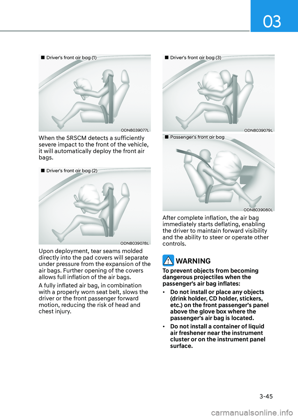
„„Driver’s front air bag (1)
ODN8039077L
When the SRSCM detects a sufficiently
severe impact to the front of the vehicle,
it will automatically deploy the front air bags.
„„Driver’s front air bag (2)
ODN8039078L
Upon deployment, tear seams molded
directly into the pad covers will separate
under pressure from the expansion of the
air bags. Further opening of the covers
allows full inflation of the air bags.
A fully inflated air bag, in combination
with a properly worn seat belt, slows the
driver or the front passenger forward
motion, reducing the risk of head and
chest injury.
„„Driver’s front air bag (3)
ODN8039079L
„„Passenger’s front air bag
ODN8039080L
After complete inflation, the air bag
immediately starts deflating, enabling
the driver to maintain forward visibility
and the ability to steer or operate other
controls.
WARNING
To prevent objects from becoming
dangerous projectiles when the
passenger’s air bag inflates: • Do not install or place any objects
(drink holder, CD holder, stickers,
etc.) on the front passenger’s panel
above the glove box where the
passenger’s air bag is located.
• Do not install a container of liquid
air freshener near the instrument
cluster or on the instrument panel
surface.
Page 87 of 555

4
Instrument Cluster ......................................................................................... 4-2
Instrument Cluster Control ...................................................................................... 4-4
Gauges and Meters .................................................................................................. 4-4
Transmission Shift Indicator .................................................................................... 4-9
Warning and Indicator Lights ................................................................................. 4-11
LCD Display Messages ............................................................................................ 4-19
LCD Display (Type A, B) ............................................................................... 4-22
LCD Display Control ............................................................................................... 4-22
LCD Display Modes ................................................................................................ 4-23
Trip Computer......................................................................................................... 4-34
LCD display (Type C) .................................................................................... 4-37
LCD Display Control ............................................................................................... 4-37
View Modes ............................................................................................................ 4-38
Utility View Mode ................................................................................................... 4-39
Option Menu ............................................................................................................ 4-41
User Settings Mode ................................................................................................ 4-42
LCD display (Type D) .................................................................................... 4-49
LCD Display Control ............................................................................................... 4-49
View Modes ........................................................................................................... 4-50
Utility View Mode ................................................................................................... 4-51
Option Menu .......................................................................................................... 4-53
User Settings Mode .............................................................................................. 4-54
4. Instrument Cluster
Page 88 of 555
4-2
Instrument Cluster
ODN8A049039C/ODN8A049032C
Instrument Cluster
1. Tachometer
2. Speedometer
3. Engine coolant temperature gauge4.
Fuel gauge
5. Warning and indicator lights
6. LCD display (including trip computer)
The actual cluster in the vehicle may differ from the illustration.
For more information, refer to the "Gauges and Meters" in this chapter.
„„Type A
„
„Type B
Page 90 of 555
Instrument Cluster
4-4
Instrument Cluster Control
Adjusting instrument cluster
illumination
ODN8A059337
When the vehicle's parking lamps or
headlamps are on, press the illumination
control button to adjust the brightness of
the instrument panel illumination.
When pressing the illumination control
button, the interior switch illumination
intensity is also adjustable. • The brightness of the instrument
panel illumination is displayed.
• If the brightness reaches the
maximum or minimum level, a chime will sound.
WARNING
Never adjust the instrument cluster
while driving. Doing so could lead to
driver distraction which may cause an
accident and lead to vehicle damage,
serious injury, or death.
Gauges and Meters
Speedometer
„„Type C
„„Type A, B
„
„Type D
OLX2048102C/OLX2049139C
OCN7040005
The speedometer indicates the speed of
the vehicle and is calibrated in kilometers
per hour (km/h) and/or miles per hour (MPH).
Page 92 of 555
Instrument Cluster
4-6
NOTICE
If the gauge pointer moves beyond
the normal range area toward the "H"
position, it indicates overheating that
may damage the engine.
Do not continue driving with an
overheated engine. If your engine
overheats, refer to "If the Engine
Overheats" in chapter 7.
WARNING
Never remove the radiator cap or
reservoir cap when the engine is hot.
The engine coolant is under pressure
and could severely burn. Wait until the
engine is cool before adding coolant to
the reservoir. Fuel gauge
„„Type A, B
ODN8A049040
„„Type C
ODN8A049007
„„Type D
OCN7040011
This gauge indicates the approximate
amount of fuel remaining in the fuel tank.
Page 94 of 555
Instrument Cluster
4-8
Odometer
„„Type A, B
OIG046114
„„Type C
ODN8A049037C
„„Type D
OCN7040015
The odometer indicates the total
distance that the vehicle has been
driven and should be used to determine
when periodic maintenance should be
performed. Range
„„Type A, B
OPD046138
„„Type C
ODN8A049033C
„„Type D
OCN7040016
• The range is the estimated distance
the vehicle can be driven with the
remaining fuel.
• If the estimated distance is below
1 km (1 mi.), the trip computer will
display "----" as range.