2023 HYUNDAI KONA EV battery
[x] Cancel search: batteryPage 505 of 548
09
9-29
Ply
A layer of rubber-coated parallel
cords.
Pneumatic tire
A mechanical device made of rubber,
chemicals, fabric and steel or other
materials, that, when mounted on
an automotive wheel provides the
traction and contains the gas or fluid
that sustains the load.
Pneumatic options weight
The combined weight of installed
regular production options weighing
over 5 lb. (2.3 kg) in excess of the
standard items which they replace,
not previously considered in
curb weight or accessory weight,
including heavy duty breaks, ride
levelers, roof rack, heavy duty
battery, and special trim.
Recommended inflation pressure
Vehicle manufacturer’s
recommended tire inflation pressure
as shown on the tire placard.
Radial ply tire
A pneumatic tire in which the ply
cords that extend to the beads are
laid at 90 degrees to the centerline
of the tread. Rim
A metal support for a tire and upon
which the tire beads are seated.
Sidewall
The portion of a tire between the
tread and the bead.
Speed rating
An alphanumeric code assigned to a
tire indicating the maximum speed
at which a tire can operate.
Traction
The friction between the tire and
the road surface. The amount of grip
provided.
Tread
The portion of a tire that comes into
contact with the road.
Treadwear indicators
Narrow bands, sometimes called
“wear bars”, that show across the
tread of a tire when only 1/16 inch of
tread remains.
UTQGS
Uniform Tire Quality Grading
Standards is a tire information
system that provides consumers
with ratings for a tire’s traction,
temperature and treadwear.
Ratings are determined by tire
manufacturers using government
testing procedures. The ratings are
molded into the sidewall of the tire.
Vehicle capacity weight
The number of designated seating
positions multiplied by 68 kg (150
lbs.) plus the rated cargo and luggage load.
Vehicle maximum load on the tire
Load on an individual tire due to curb
and accessory weight plus maximum
occupant and cargo weight.
Page 508 of 548
![HYUNDAI KONA EV 2023 Owners Manual Maintenance
9-32
FUSES
„„Blade type
AB
„
„Cartridge type
„
„Multi fuse
OTM078035
AB
AB
[A] : Normal, [B] : Blown
A vehicle’s electrical system is protected
from elect HYUNDAI KONA EV 2023 Owners Manual Maintenance
9-32
FUSES
„„Blade type
AB
„
„Cartridge type
„
„Multi fuse
OTM078035
AB
AB
[A] : Normal, [B] : Blown
A vehicle’s electrical system is protected
from elect](/manual-img/35/56170/w960_56170-507.png)
Maintenance
9-32
FUSES
„„Blade type
AB
„
„Cartridge type
„
„Multi fuse
OTM078035
AB
AB
[A] : Normal, [B] : Blown
A vehicle’s electrical system is protected
from electrical overload damage by fuses.
This vehicle has 2 (or 3) fuse panels, one
located in the driver’s side panel bolster,
the other in the motor compartment.
If any of your vehicle’s lights,
accessories, or controls do not work,
check the appropriate circuit fuse. If a
fuse has blown, the element inside the
fuse will be melted or broken.
If the electrical system does not work,
first check the driver’s side fuse panel.
Before replacing a blown fuse, turn the
vehicle and all switches off, and then
disconnect the negative battery cable.
Always replace a blown fuse with one of
the same rating.
If the replacement fuse blows, this
indicates an electrical problem.
Avoid using the system involved and it is
recommended to consult an authorized
dealer.
Information
Three kinds of fuses are used: blade type
for lower amperage rating, cartridge
type, and multi fuse for higher amperage ratings.
WARNING
NEVER replace a fuse with anything but
another fuse of the same rating. • A higher capacity fuse could cause
damage and possibly cause a fire.
• Do not install a wire or aluminum
foil instead of the proper fuse -
even as a temporary repair. It may
cause extensive wiring damage and
possibly a fire.
NOTICE
Do not use a screwdriver or any other
metal object to remove fuses because
it may cause a short circuit and damage
the system.
Page 511 of 548
09
9-35
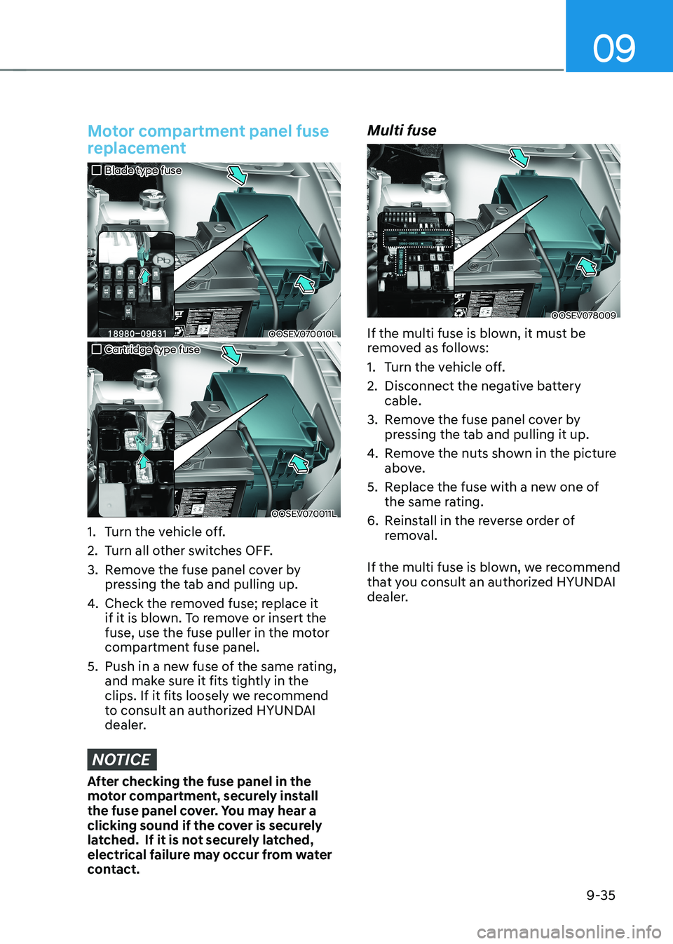
Motor compartment panel fuse
replacement
„„Blade type fuse
OOSEV070010L
„„Cartridge type fuse
OOSEV070011L
1. Turn the vehicle off.
2. Turn all other switches OFF.
3. Remove the fuse panel cover by pressing the tab and pulling up.
4. Check the removed fuse; replace it
if it is blown. To remove or insert the
fuse, use the fuse puller in the motor
compartment fuse panel.
5. push in a new fuse of the same rating, and make sure it fits tightly in the
clips. If it fits loosely we recommend
to consult an authorized HYUNDAI
dealer.
NOTICE
After checking the fuse panel in the
motor compartment, securely install
the fuse panel cover. You may hear a
clicking sound if the cover is securely
latched. If it is not securely latched,
electrical failure may occur from water
contact. Multi fuse
OOSEV078009
If the multi fuse is blown, it must be
removed as follows:
1. Turn the vehicle off.
2. Disconnect the negative battery cable.
3. Remove the fuse panel cover by pressing the tab and pulling it up.
4. Remove the nuts shown in the picture
above.
5. Replace the fuse with a new one of the same rating.
6. Reinstall in the reverse order of removal.
If the multi fuse is blown, we recommend
that you consult an authorized HYUNDAI
dealer.
Page 517 of 548

09
9-41
Motor compartment fuse panel
TypeFuse Name Fuse
Rating Circuit Protected
MULTI
FUSE-3 LDC
150AE/R Junction Block (Fuse - IEB 1, IEB 2,
CHARGER 1, HEATED STEERING), EpCU (LDC)
MDpS 80AMDpS Unit
MULTI
FUSE-1 B+ 5
60ApCB Block ((Fuse - BATTERY MANAGEMENT 1,
HORN, EpCU 1), IG3 MAIN Relay)
B+ 2 60AIGpM ((Fuse - S/HEATER FRT), IpS0, IpS1, IpS2)
B+ 3 60AIGpM (IpS3, IpS5, IpS6, IpS7)
B+ 4 50AIGpM (Fuse - p/WINDOW LH, p/WINDOW
RH, TAILGATE OpEN, SUNROOF, AMp, p/SEAT
(DRV), p/SEAT (pASS), S/HEATER REAR)
COOLING FAN 60AE/R Junction Block (Cooling Fan Relay)
REAR HEATED 40AE/R Junction Block (Rear Heated Relay)
IG1 40AE/R Junction Block (pDM (IG1) 2 Relay, pDM
(ACC) 1 Relay)
IG2 40AE/R Junction Block (pDM (IG2) 3 Relay)
MULTI
FUSE-2 IEB 4
40AElectronic Brake Control Module
BLOWER 40AE/R Junction Block (Blower Relay)
Page 519 of 548
09
9-43
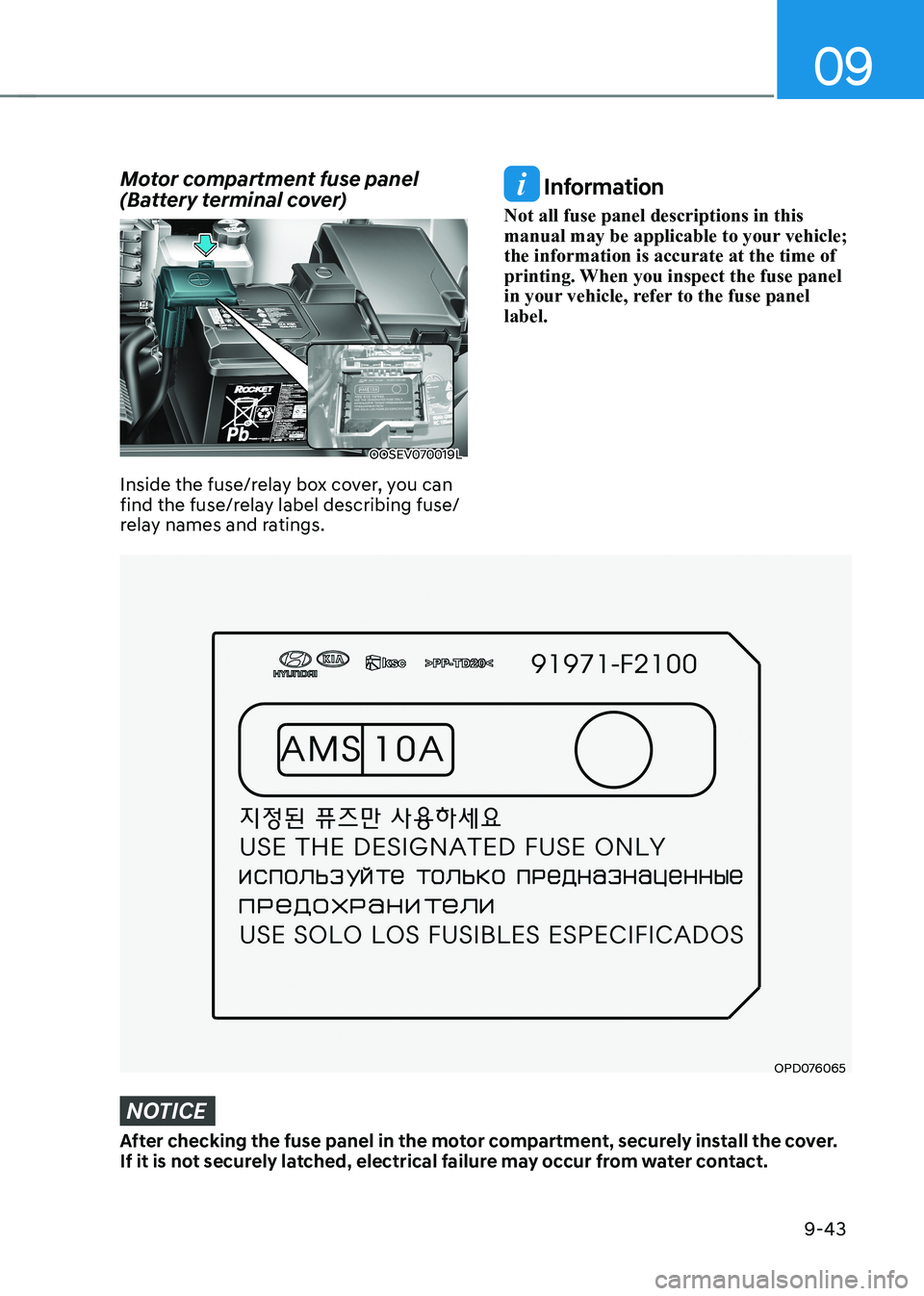
Motor compartment fuse panel
(Battery terminal cover)
OOSEV070019L
Inside the fuse/relay box cover, you can
find the fuse/relay label describing fuse/
relay names and ratings.
OPD076065
Information
Not all fuse panel descriptions in this
manual may be applicable to your vehicle; the information is accurate at the time of
printing. When you inspect the fuse panel
in your vehicle, refer to the fuse panel label.
NOTICE
After checking the fuse panel in the motor compartment, securely install the cover.
If it is not securely latched, electrical failure may occur from water contact.
Page 521 of 548
09
9-45
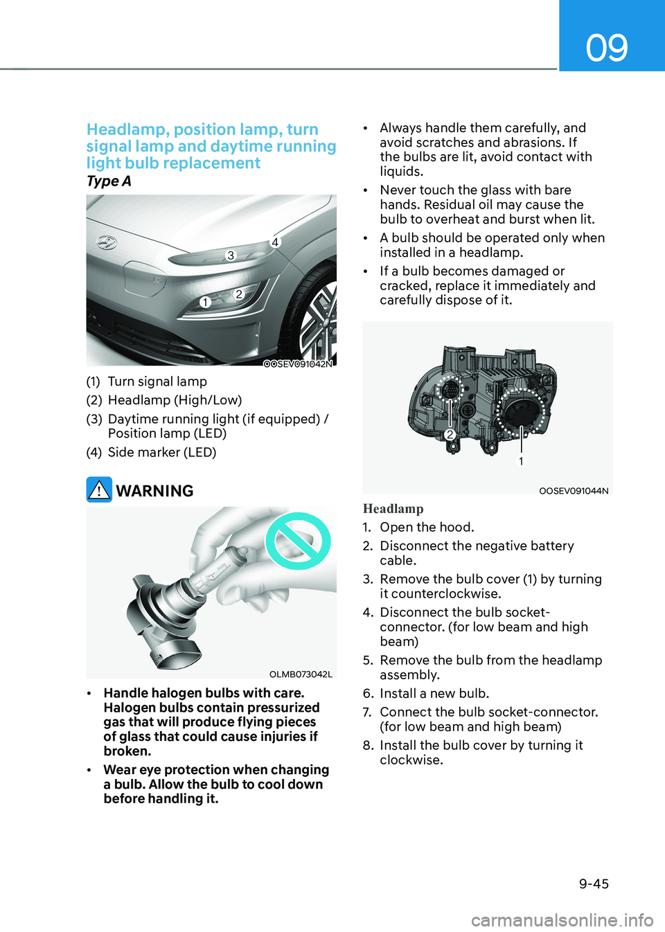
Headlamp, position lamp, turn
signal lamp and daytime running
light bulb replacement
Type A
OOSEV091042N
(1) Turn signal lamp
(2) Headlamp (High/Low)
(3) Daytime running light (if equipped) / position lamp (LED)
(4) Side marker (LED)
WARNING
OLMB073042L
• Handle halogen bulbs with care.
Halogen bulbs contain pressurized
gas that will produce flying pieces
of glass that could cause injuries if
broken.
• Wear eye protection when changing
a bulb. Allow the bulb to cool down
before handling it. •
Always handle them carefully, and
avoid scratches and abrasions. If
the bulbs are lit, avoid contact with liquids.
• Never touch the glass with bare
hands. Residual oil may cause the
bulb to overheat and burst when lit.
• A bulb should be operated only when
installed in a headlamp.
• If a bulb becomes damaged or
cracked, replace it immediately and
carefully dispose of it.
OOSEV091044N
Headlamp
1. Open the hood.
2. Disconnect the negative battery
cable.
3. Remove the bulb cover (1) by turning it counterclockwise.
4. Disconnect the bulb socket-
connector. (for low beam and high
beam)
5. Remove the bulb from the headlamp assembly.
6. Install a new bulb.
7. Connect the bulb socket-connector.
(for low beam and high beam)
8. Install the bulb cover by turning it clockwise.
Page 522 of 548
Maintenance
9-46
OOSEV091044N
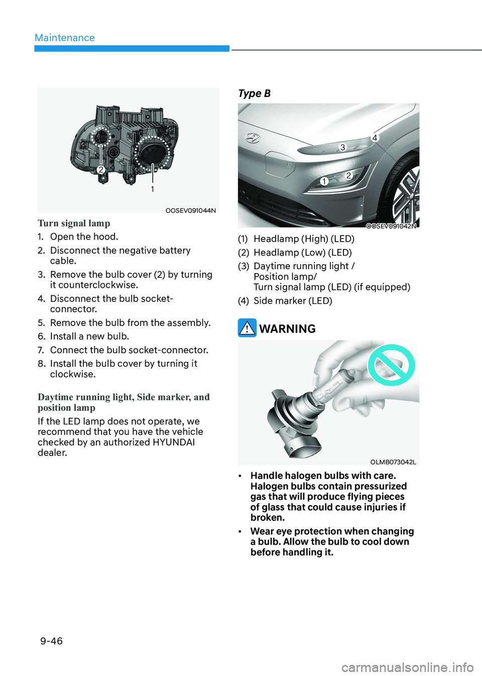
Turn signal lamp
1. Open the hood.
2. Disconnect the negative battery cable.
3. Remove the bulb cover (2) by turning it counterclockwise.
4. Disconnect the bulb socket-
connector.
5. Remove the bulb from the assembly.
6. Install a new bulb.
7. Connect the bulb socket-connector.
8. Install the bulb cover by turning it clockwise.
Daytime running light, Side marker, and position lamp
If the LED lamp does not operate, we
recommend that you have the vehicle
checked by an authorized HYUNDAI
dealer. Type B
OOSEV091042N
(1) Headlamp (High) (LED)
(2) Headlamp (Low) (LED)
(3) Daytime running light / position lamp/
Turn signal lamp (LED) (if equipped)
(4) Side marker (LED)
WARNING
OLMB073042L
• Handle halogen bulbs with care.
Halogen bulbs contain pressurized
gas that will produce flying pieces
of glass that could cause injuries if
broken.
• Wear eye protection when changing
a bulb. Allow the bulb to cool down
before handling it.
Page 537 of 548
Index
I-2
A Accessing your vehicle .......................................................................................... 5-4
Auto door lock/unlock features ........................................................................ 5-13
Child-protector rear door locks ........................................................................ 5-14
Door locks ....................................................................................................... 5-10
Immobilizer system ............................................................................................ 5-9
Operating door locks from inside the vehicle ..................................................5-11
Operating door locks from outside the vehicle ................................................5-10
Rear Occupant Alert (ROA) ............................................................................. 5-14
Smart key .......................................................................................................... 5-4
Air bag - supplemental restraint system .............................................................. 3-42
Additional safety precautions ........................................................................... 3-64
Air bag warning labels ..................................................................................... 3-64
How does the air bags system operate? ............................................................3-47
Occupant Classification System (OCS) ...........................................................3-51
SRS care ........................................................................................................... 3-63
What to expect after an air bag inflates ............................................................3-51
Where are the air bags? .................................................................................... 3-44
Why didn’t my air bag go off in a collision? ...................................................3-57
Air conditioner compressor label......................................................................... 2-13 Air conditioning system ....................................................................................... 2-10
Appearance care................................................................................................... 9-52
Exterior care ..................................................................................................... 9-52
Interior care ...................................................................................................... 9-57
Automatic climate control system ....................................................................... 5-62
Automatic heating and air conditioning ...........................................................5-63
Manual heating and air conditioning ................................................................ 5-64
System maintenance ......................................................................................... 5-73
System operation .............................................................................................. 5-71
B
Battery (12 Volt) .................................................................................................. 9-17
Battery capacity label ....................................................................................... 9-18
Battery recharging ............................................................................................ 9-18
Battery usage .................................................................................................... 9-18
Reset items ....................................................................................................... 9-19