2023 GMC SIERRA weight
[x] Cancel search: weightPage 279 of 430
GMC Sierra/Sierra Denali 2500 HD/3500 HD Owner Manual (GMNA-
Localizing-U.S./Canada-16504257) - 2023 - CRC - 5/9/22
278 Driving and Operating
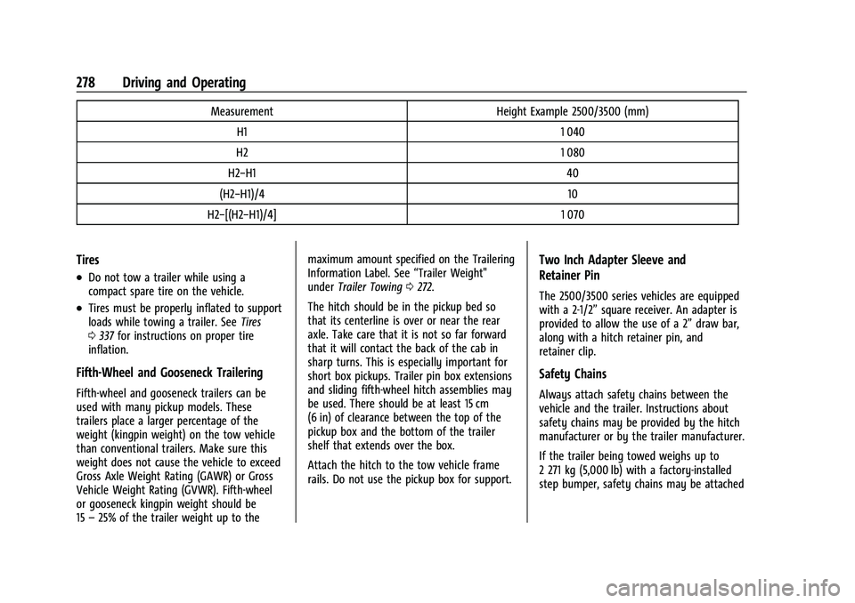
MeasurementHeight Example 2500/3500 (mm)
H1 1 040
H2 1 080
H2−H1 40
(H2−H1)/4 10
H2−[(H2−H1)/4] 1 070
Tires
.Do not tow a trailer while using a
compact spare tire on the vehicle.
.Tires must be properly inflated to support
loads while towing a trailer. SeeTires
0 337 for instructions on proper tire
inflation.
Fifth-Wheel and Gooseneck Trailering
Fifth-wheel and gooseneck trailers can be
used with many pickup models. These
trailers place a larger percentage of the
weight (kingpin weight) on the tow vehicle
than conventional trailers. Make sure this
weight does not cause the vehicle to exceed
Gross Axle Weight Rating (GAWR) or Gross
Vehicle Weight Rating (GVWR). Fifth-wheel
or gooseneck kingpin weight should be
15 –25% of the trailer weight up to the maximum amount specified on the Trailering
Information Label. See
“Trailer Weight"
under Trailer Towing 0272.
The hitch should be in the pickup bed so
that its centerline is over or near the rear
axle. Take care that it is not so far forward
that it will contact the back of the cab in
sharp turns. This is especially important for
short box pickups. Trailer pin box extensions
and sliding fifth-wheel hitch assemblies may
be used. There should be at least 15 cm
(6 in) of clearance between the top of the
pickup box and the bottom of the trailer
shelf that extends over the box.
Attach the hitch to the tow vehicle frame
rails. Do not use the pickup box for support.
Two Inch Adapter Sleeve and
Retainer Pin
The 2500/3500 series vehicles are equipped
with a 2-1/2” square receiver. An adapter is
provided to allow the use of a 2” draw bar,
along with a hitch retainer pin, and
retainer clip.
Safety Chains
Always attach safety chains between the
vehicle and the trailer. Instructions about
safety chains may be provided by the hitch
manufacturer or by the trailer manufacturer.
If the trailer being towed weighs up to
2 271 kg (5,000 lb) with a factory-installed
step bumper, safety chains may be attached
Page 280 of 430
GMC Sierra/Sierra Denali 2500 HD/3500 HD Owner Manual (GMNA-
Localizing-U.S./Canada-16504257) - 2023 - CRC - 5/9/22
Driving and Operating 279
to the attaching points on the bumper;
otherwise, safety chains should be attached
to holes on the trailer hitch.
Cross the safety chains under the tongue of
the trailer to help prevent the tongue from
contacting the road if it becomes separated
from the hitch. Always leave enough slack in
the safety chains to allow the combination
to turn. Never allow safety chains to drag
on the ground.
Trailer Brakes
Loaded trailers over 900 kg (2,000 lb) must
be equipped with brake systems and with
brakes for each axle. Trailer braking
equipment conforming to Canadian
Standards Association (CSA) requirement
CAN3-D313, or its equivalent, is
recommended.
State or local regulations may require
trailers to have their own braking system if
the loaded weight of the trailer exceeds
certain minimums that can vary from state
to state. Read and follow the instructions for
the trailer brakes so they are installed,
adjusted, and maintained properly. Never
attempt to tap into your vehicle's hydraulicbrake system. If you do, both the vehicle
antilock brakes and the trailer brakes may
not function, which could result in a crash.
Auxiliary Battery
If equipped, the vehicle's auxiliary battery
can be used to supply electrical power to
additional equipment that may be added,
such as a slide-in camper.
Locate the auxiliary battery connector under
the hood on the driver side of the vehicle,
next to the engine compartment fuse block.
Follow the proper installation instructions
included with any electrical equipment that
is installed.
Caution
To prevent draining the auxiliary battery,
always turn off electrical equipment
when not in use and do not use any
equipment that may exceed the
maximum amperage rating of 30 amps.
Trailer Wiring Harness
Basic Trailer Wiring
If the vehicle is not equipped with a trailer
connector on the rear bumper, a 7-wire
trailering harness is tied to the vehiclesframe. The harness requires the installation
of a trailer connector, which is available
through your dealer.
Use only a round, seven-wire connector with
flat blade terminals meeting SAE J2863
specifications for proper electrical
connectivity.
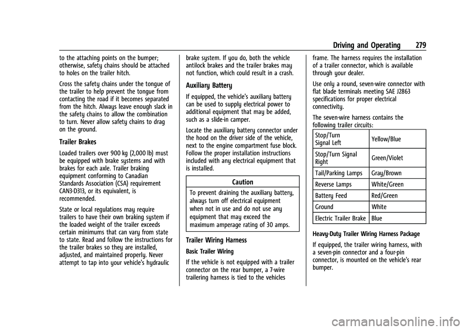
The seven-wire harness contains the
following trailer circuits:
Stop/Turn
Signal Left Yellow/Blue
Stop/Turn Signal
Right Green/Violet
Tail/Parking Lamps Gray/Brown
Reverse Lamps White/Green
Battery Feed Red/Green
Ground White
Electric Trailer Brake Blue
Heavy-Duty Trailer Wiring Harness Package
If equipped, the trailer wiring harness, with
a seven-pin connector and a four-pin
connector, is mounted on the vehicle's rear
bumper.
Page 283 of 430
GMC Sierra/Sierra Denali 2500 HD/3500 HD Owner Manual (GMNA-
Localizing-U.S./Canada-16504257) - 2023 - CRC - 5/9/22
282 Driving and Operating
Turn Signals When Towing a Trailer
When properly connected, the trailer turn
signals will illuminate to indicate the vehicle
is turning, changing lanes, or stopping.
When towing a trailer, the arrows on the
instrument cluster will illuminate even if the
trailer is not properly connected or the bulbs
are burned out.
Tow/Haul Mode
For instructions on how to enter Tow/Haul
Mode, seeDriver Mode Control 0243.
Tow/Haul assists when pulling a heavy
trailer or a large or heavy load. See Tow/
Haul Mode 0234.
Tow/Haul Mode is designed to be most
effective when the vehicle and trailer
combined weight is at least 75% of the
vehicle's Gross Combined Weight Rating
(GCWR). See “Trailer Weight” underTrailer
Towing 0272.
Tow/Haul Mode is most useful when towing
a heavy trailer or carrying a large or
heavy load:
.Through rolling terrain.
.In stop-and-go traffic.
.In busy parking lots. Operating the vehicle in Tow/Haul Mode
when lightly loaded or not towing will not
cause damage; however, it is not
recommended and may result in unpleasant
engine and transmission driving
characteristics, heavy or light steering
efforts, and reduced fuel economy.
Integrated Trailer Brake Control System
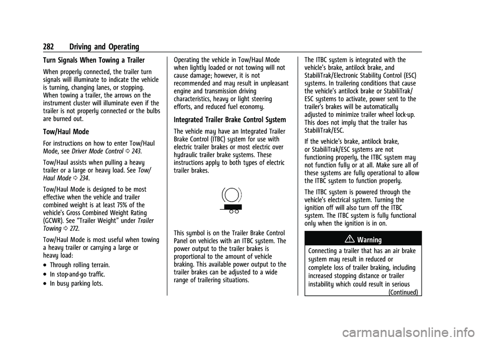
The vehicle may have an Integrated Trailer
Brake Control (ITBC) system for use with
electric trailer brakes or most electric over
hydraulic trailer brake systems. These
instructions apply to both types of electric
trailer brakes.
This symbol is on the Trailer Brake Control
Panel on vehicles with an ITBC system. The
power output to the trailer brakes is
proportional to the amount of vehicle
braking. This available power output to the
trailer brakes can be adjusted to a wide
range of trailering situations.
The ITBC system is integrated with the
vehicle’s brake, antilock brake, and
StabiliTrak/Electronic Stability Control (ESC)
systems. In trailering conditions that cause
the vehicle’s antilock brake or StabiliTrak/
ESC systems to activate, power sent to the
trailer's brakes will be automatically
adjusted to minimize trailer wheel lock-up.
This does not imply that the trailer has
StabiliTrak/ESC.
If the vehicle’s brake, antilock brake,
or StabiliTrak/ESC systems are not
functioning properly, the ITBC system may
not function fully or at all. Make sure all of
these systems are fully operational to allow
the ITBC system to function properly.
The ITBC system is powered through the
vehicle's electrical system. Turning the
ignition off will also turn off the ITBC
system. The ITBC system is fully functional
only when the ignition is in on.{Warning
Connecting a trailer that has an air brake
system may result in reduced or
complete loss of trailer braking, including
increased stopping distance or trailer
instability which could result in serious
(Continued)
Page 288 of 430
GMC Sierra/Sierra Denali 2500 HD/3500 HD Owner Manual (GMNA-
Localizing-U.S./Canada-16504257) - 2023 - CRC - 5/9/22
Driving and Operating 287
If the vehicle is equipped with a trailer tire
pressure monitoring system, see the trailer
tire pressure monitoring system description
and the trailering app.
Trailer tires deteriorate over time. The trailer
tire sidewall will show the week and year
the tire was manufactured. Many trailer tire
manufacturers recommend replacing tires
more than six years old.
Overloading is another leading cause of
trailer tire blow-outs. Never load your trailer
with more weight than the tires are
designed to support. The load rating is
located on the trailer tire sidewall.
Always know the maximum speed rating for
the trailer tires before driving. This may be
significantly lower than the vehicle tire
speed rating. The speed rating may be on
the trailer tire sidewall. If the speed rating is
not shown, the default trailer tire speed
rating is 105 km/h (65 mph).
Trailering App
Trailer Lights App
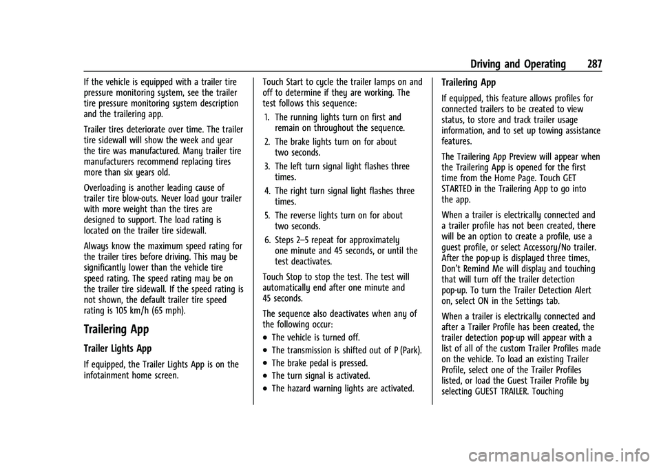
If equipped, the Trailer Lights App is on the
infotainment home screen.Touch Start to cycle the trailer lamps on and
off to determine if they are working. The
test follows this sequence:
1. The running lights turn on first and remain on throughout the sequence.
2. The brake lights turn on for about two seconds.
3. The left turn signal light flashes three times.
4. The right turn signal light flashes three times.
5. The reverse lights turn on for about two seconds.
6. Steps 2–5 repeat for approximately one minute and 45 seconds, or until the
test deactivates.
Touch Stop to stop the test. The test will
automatically end after one minute and
45 seconds.
The sequence also deactivates when any of
the following occur:
.The vehicle is turned off.
.The transmission is shifted out of P (Park).
.The brake pedal is pressed.
.The turn signal is activated.
.The hazard warning lights are activated.
Trailering App
If equipped, this feature allows profiles for
connected trailers to be created to view
status, to store and track trailer usage
information, and to set up towing assistance
features.
The Trailering App Preview will appear when
the Trailering App is opened for the first
time from the Home Page. Touch GET
STARTED in the Trailering App to go into
the app.
When a trailer is electrically connected and
a trailer profile has not been created, there
will be an option to create a profile, use a
guest profile, or select Accessory/No trailer.
After the pop-up is displayed three times,
Don’t Remind Me will display and touching
that will turn off the trailer detection
pop-up. To turn the Trailer Detection Alert
on, select ON in the Settings tab.
When a trailer is electrically connected and
after a Trailer Profile has been created, the
trailer detection pop-up will appear with a
list of all of the custom Trailer Profiles made
on the vehicle. To load an existing Trailer
Profile, select one of the Trailer Profiles
listed, or load the Guest Trailer Profile by
selecting GUEST TRAILER. Touching
Page 299 of 430

GMC Sierra/Sierra Denali 2500 HD/3500 HD Owner Manual (GMNA-
Localizing-U.S./Canada-16504257) - 2023 - CRC - 5/9/22
298 Driving and Operating
Caution
Some electrical equipment can damage
the vehicle or cause components to not
work and would not be covered by the
vehicle warranty. Always check with your
dealer before adding electrical equipment.
Add-on equipment can drain the vehicle's
12-volt battery, even if the vehicle is not
operating.
The vehicle has an airbag system. Before
attempting to add anything electrical to the
vehicle, see Servicing the Airbag-Equipped
Vehicle 073 and
Adding Equipment to the Airbag-Equipped
Vehicle 074.
For information on wiring auxiliary switches,
see www.gmupfitter.com or contact your
dealer.
Adding a Snow Plow or Similar
Equipment
Caution
Do not exceed 72 km/h (45 mph) with a
snow plow mounted to the vehicle. The
vehicle could overheat and be damaged.
Before installing a snow plow on the vehicle,
follow these guidelines:
Caution
If the vehicle does not have the snow
plow prep package, RPO VYU, adding a
plow can damage the vehicle, and the
repairs would not be covered by the
vehicle warranty. Unless the vehicle was
built to carry a snow plow, do not add
one to the vehicle. If the vehicle has RPO
VYU, then the payload the vehicle can
carry will be reduced when a snow plow
is installed. The vehicle can be damaged
if either the front or rear axle ratings or
the Gross Vehicle Weight Rating (GVWR)
are exceeded. The plow the vehicle can carry depends on
many things, such as:
.The options the vehicle came with, and
the weight of those options.
.The weight and number of passengers to
be carried.
.The weight of items added to the vehicle,
like a tool box or truck cap.
.The total weight of any additional cargo
to be carried.
To safely carry a snow plow on the vehicle:
.With a snow plow attached, the engine
coolant temperature gauge may show a
higher temperature than while driving
without one. The snow plow could block
the airflow to the radiator. This could be
more noticeable as vehicle speed
increases. At speeds above 72 km/h
(45 mph), this may cause the engine
coolant to overheat. Move or angle the
snow plow blade to allow increased
airflow to the radiator.
.To increase the airflow, move the snow
plow blade position.
.If driving more than 24 km/h (15 mph),
angle the plow blade position.
Page 300 of 430
GMC Sierra/Sierra Denali 2500 HD/3500 HD Owner Manual (GMNA-
Localizing-U.S./Canada-16504257) - 2023 - CRC - 5/9/22
Driving and Operating 299
.Make sure the weight on the front and
rear axles does not exceed the axle rating
for each.
.Follow the snowplow manufacturer’s
recommendations for any rear ballast that
may be required. Rear ballast may be
required to ensure a proper front and rear
weight distribution ratio even though the
actual weight at the front axle may be
less than the front axle rating.
.The snowplow manufacturer or installer
can assist in determining the amount of
rear ballast required to ensure that the
vehicle with the attached snowplow does
not exceed the GVW rating, the front and
rear axle ratings, or the front and rear
weight distribution ratio (refer to the GM
Upfitter Manual).
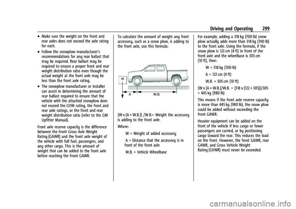
Front axle reserve capacity is the difference
between the Front Gross Axle Weight
Rating (GAWR) and the front axle weight of
the vehicle with full fuel, passengers, and
any other cargo. This is the amount of
weight that can be added to the front axle
before reaching the Front GAWR. To calculate the amount of weight any front
accessory, such as a snow plow, is adding to
the front axle, use this formula:
(W x (A + W.B.)) /W.B.= Weight the accessory
is adding to the front axle.
Where:
IW = Weight of added accessory
IA = Distance that the accessory is in
front of the front axle
IW.B. = Vehicle Wheelbase For example, adding a 318 kg (700 lb) snow
plow actually adds more than 318 kg (700 lb)
to the front axle. Using the formula, if the
snow plow is 122 cm (4 ft) in front of the
front axle and the wheelbase is 305 cm
(10 ft), then:
IW = 318 kg (700 lb)
IA = 122 cm (4 ft)
IW.B. = 305 cm (10 ft)
(W x (A + W.B.)/W.B. = (318 x (122 + 305))/305
= 445 kg (980 lb)
This means if the front axle reserve capacity
is more than 445 kg (980 lb), the snow plow
could be added without exceeding the
front GAWR.
Heavier equipment can be added on the
front of the vehicle if less cargo or fewer
passengers are carried, or by positioning
cargo toward the rear. This reduces the load
on the front. However, the front GAWR, rear
GAWR, and Gross Vehicle Weight
Rating (GVWR) must never be exceeded.
Page 301 of 430
GMC Sierra/Sierra Denali 2500 HD/3500 HD Owner Manual (GMNA-
Localizing-U.S./Canada-16504257) - 2023 - CRC - 5/9/22
300 Driving and Operating
{Warning
On some vehicles that have certain front
mounted equipment, such as a snow
plow, it may be possible to load the front
axle to the front Gross Axle Weight
Rating (GAWR) but not have enough
weight on the rear axle to have proper
braking performance. If the brakes cannot
work properly, the vehice could crash.
Always follow the snow plow
manufacturer or installer's
recommendation for rear ballast to
ensure a proper front and rear weight
distribution ratio. Maintaining a proper
front and rear weight distribution ratio is
necessary to provide proper braking
performance.
See your dealer for additional advice and
information about using a snow plow on the
vehicle. Also, see Vehicle Load Limits 0215.
Pickup Conversion to Chassis Cab
We are aware that some vehicle owners
might consider having the pickup box
removed and a commercial or recreational
body installed. Owners should be aware
that, as manufactured, there are differences
between a chassis cab and a pickup with the
box removed which could affect vehicle
safety. The components necessary to adapt
a pickup to permit its safe use with a
specialized body should be installed by the
body builder.
Page 342 of 430
GMC Sierra/Sierra Denali 2500 HD/3500 HD Owner Manual (GMNA-
Localizing-U.S./Canada-16504257) - 2023 - CRC - 5/18/22
Vehicle Care 341
GVWR:Gross Vehicle Weight Rating.
See Vehicle Load Limits 0215.
GAWR FRT
:Gross Axle Weight Rating
for the front axle. See Vehicle Load
Limits 0215.
GAWR RR
:Gross Axle Weight Rating
for the rear axle. See Vehicle Load
Limits 0215.
Intended Outboard Sidewall
:The side
of an asymmetrical tire, that must
always face outward when mounted on
a vehicle.
Kilopascal (kPa)
:The metric unit for air
pressure.
Light Truck (LT-Metric) Tire
:A tire used
on light duty trucks and some
multipurpose passenger vehicles.
Load Index
:An assigned number
ranging from 1 to 279 that corresponds
to the load carrying capacity of a tire.
Maximum Inflation Pressure
:The
maximum air pressure to which a cold
tire can be inflated. The maximum air
pressure is molded onto the sidewall. Maximum Load Rating
:The load rating
for a tire at the maximum permissible
inflation pressure for that tire.
Occupant Distribution
:Designated
seating positions.
Outward Facing Sidewall
:The side of
an asymmetrical tire that has a
particular side that faces outward when
mounted on a vehicle. The side of the
tire that contains a whitewall, bears
white lettering, or bears manufacturer,
brand, and/or model name molding
that is higher or deeper than the same
moldings on the other sidewall of
the tire.
Passenger (P-Metric) Tire
:A tire used
on passenger cars and some light duty
trucks and multipurpose vehicles.
Recommended Inflation Pressure
:
Vehicle manufacturer's recommended
tire inflation pressure as shown on the
tire placard. See Tire Pressure0342 and
Vehicle Load Limits 0215. Radial Ply Tire
:A pneumatic tire in
which the ply cords that extend to the
beads are laid at 90 degrees to the
centerline of the tread.
Rim
:A metal support for a tire and
upon which the tire beads are seated.
Sidewall
:The portion of a tire between
the tread and the bead.
Speed Rating
:An alphanumeric code
assigned to a tire indicating the
maximum speed at which a tire can
operate.
Traction
:The friction between the tire
and the road surface. The amount of
grip provided.
Tread
:The portion of a tire that comes
into contact with the road.
Treadwear Indicators
:Narrow bands,
sometimes called wear bars, that show
across the tread of a tire when only
1.6 mm (1/16 in) of tread remains. See
When It Is Time for New Tires 0351.