2023 GMC SIERRA engine
[x] Cancel search: enginePage 332 of 430

GMC Sierra/Sierra Denali 2500 HD/3500 HD Owner Manual (GMNA-
Localizing-U.S./Canada-16504257) - 2023 - CRC - 5/18/22
Vehicle Care 331
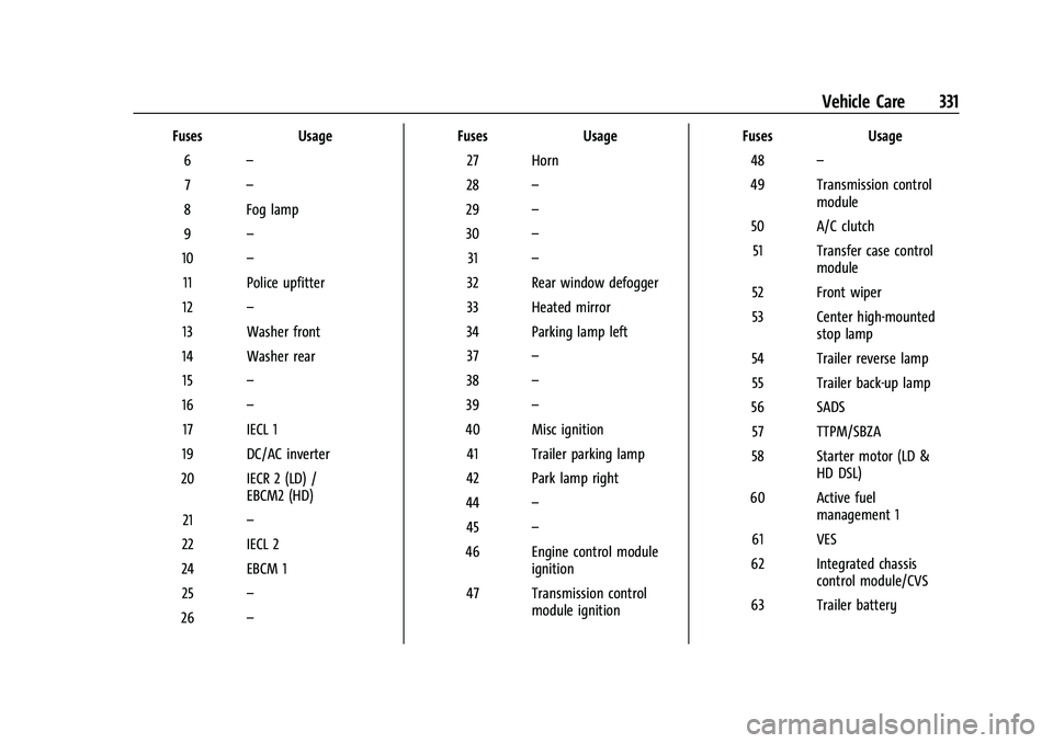
FusesUsage
6 –
7 –
8 Fog lamp
9 –
10 –
11 Police upfitter
12 –
13 Washer front
14 Washer rear 15 –
16 –
17 IECL 1
19 DC/AC inverter
20 IECR 2 (LD) / EBCM2 (HD)
21 –
22 IECL 2
24 EBCM 1 25 –
26 – Fuses
Usage
27 Horn
28 –
29 –
30 –
31 –
32 Rear window defogger
33 Heated mirror
34 Parking lamp left 37 –
38 –
39 –
40 Misc ignition 41 Trailer parking lamp
42 Park lamp right
44 –
45 –
46 Engine control module ignition
47 Transmission control module ignition Fuses
Usage
48 –
49 Transmission control module
50 A/C clutch 51 Transfer case control module
52 Front wiper
53 Center high-mounted stop lamp
54 Trailer reverse lamp 55 Trailer back-up lamp
56 SADS 57 TTPM/SBZA
58 Starter motor (LD & HD DSL)
60 Active fuel management 1
61 VES
62 Integrated chassis control module/CVS
63 Trailer battery
Page 333 of 430

GMC Sierra/Sierra Denali 2500 HD/3500 HD Owner Manual (GMNA-
Localizing-U.S./Canada-16504257) - 2023 - CRC - 5/18/22
332 Vehicle Care
FusesUsage
65 Auxiliary underhood electrical center
66 Cooling fan motor left 67 Active fuel management 2
68 –
69 Starter Pinion (LD) / Starter Motor (HD Gas)
71 Cooling fan
72 Cooling fan right/lower
73 Trailer stop/turn lamp left
74 Trailer Interface Module 1
75 DEFC
76 Electric RNG BDS
78 Engine control module
79 Auxiliary battery
80 Cabin cooling pump 81 Trailer stop/turn lamp right Fuses
Usage
82 Trailer Interface Module 2
83 FTZM
84 Trailer brake 85 ENG
86 Engine control module 87 Injector B even
88 O2 B sensor
89 O2 A sensor
90 Injector A odd 91 Engine control module throttle control
92 Cool fan clutch/ Aeroshutter Relays
Usage
5 Headlamp
18 DC/AC inverter
23 Rear window defogger
35 Parking lamp
36 Run/Crank
43 –
59 A/C clutch
64 Starter Motor (LD & HD DSL)
70 Starter Pinion (LD) / Starter Motor (HD Gas)
77 Powertrain
Page 341 of 430

GMC Sierra/Sierra Denali 2500 HD/3500 HD Owner Manual (GMNA-
Localizing-U.S./Canada-16504257) - 2023 - CRC - 5/18/22
340 Vehicle Care
Light Truck (LT-Metric) Tire
(1) Light Truck (LT-Metric) Tire:The
United States version of a metric tire
sizing system. The letters LT as the first
two characters in the tire size mean a
light truck tire engineered to standards
set by the U.S. Tire and Rim
Association.
(2) Tire Width
:The 3-digit number
indicates the tire section width in
millimeters from sidewall to sidewall.
(3) Aspect Ratio
:A 2-digit number that
indicates the tire height-to-width
measurements. For example, if the tire
size aspect ratio is 75, as shown in
item (3) of the light truck (LT-Metric)
tire illustration, it would mean that the
tire's sidewall is 75 percent as high as it
is wide. (4) Construction Code
:A letter code is
used to indicate the type of ply
construction in the tire. The letter R
means radial ply construction; the
letter D means diagonal or bias ply
construction.
(5) Rim Diameter
:Diameter of the
wheel in inches.
(6) Load Range
:Load Range.
(7) Service Description
:The service
description indicates the load index and
speed rating of a tire. If two numbers
are given as in the example, 120/116,
then this represents the load index for
single versus dual wheel usage (single/
dual). The speed rating is the maximum
speed a tire is certified to carry a load.
Tire Terminology and Definitions
Air Pressure:The amount of air inside
the tire pressing outward on each
square inch of the tire. Air pressure is
expressed in kPa (kilopascal) or psi
(pounds per square inch).
Aspect Ratio
:The relationship of a
tire's height to its width. Belt
:A rubber coated layer of cords
that is located between the plies and
the tread. Cords may be made from
steel or other reinforcing materials.
Bead
:The tire bead contains steel
wires wrapped by steel cords that hold
the tire onto the rim.
Bias Ply Tire
:A pneumatic tire in which
the plies are laid at alternate angles
less than 90 degrees to the centerline
of the tread.
Cold Tire Pressure
:The amount of air
pressure in a tire, measured in kPa
(kilopascal) or psi (pounds per square
inch) before a tire has built up heat
from driving. See Tire Pressure0342.
DOT Markings
:A code molded into the
sidewall of a tire signifying that the tire
is in compliance with the U.S.
Department of Transportation (DOT)
Motor Vehicle Safety Standards. The
DOT code includes the Tire Identification
Number (TIN), an alphanumeric
designator which can also identify the
tire manufacturer, production plant,
brand, and date of production.
Page 343 of 430

GMC Sierra/Sierra Denali 2500 HD/3500 HD Owner Manual (GMNA-
Localizing-U.S./Canada-16504257) - 2023 - CRC - 5/18/22
342 Vehicle Care
UTQGS (Uniform Tire Quality Grading
Standards)
:A tire information system
that provides consumers with ratings
for a tire's traction, temperature, and
treadwear. Ratings are determined by
tire manufacturers using government
testing procedures. The ratings are
molded into the sidewall of the tire.
See Uniform Tire Quality Grading 0353.
Vehicle Capacity Weight
:The number
of designated seating positions
multiplied by 68 kg (150 lbs) plus the
rated cargo load. See Vehicle Load
Limits 0215.
Vehicle Maximum Load on the Tire
:
Load on an individual tire due to curb
weight, accessory weight, occupant
weight, and cargo weight.
Vehicle Placard
:A label permanently
attached to a vehicle showing the
vehicle's capacity weight and the
original equipment tire size and
recommended inflation pressure. See
“Tire and Loading Information Label”
under Vehicle Load Limits 0215.
Tire Pressure
Tires need the correct amount of air
pressure to operate effectively.
{Warning
Neither tire underinflation nor
overinflation is good. Underinflated
tires, or tires that do not have
enough air, can result in:
.Tire overloading and overheating,
which could lead to a blowout
.Premature or irregular wear
.Poor handling
.Reduced fuel economy for
internal combustion engine
vehicles
.Reduced range for electric vehicles
Overinflated tires, or tires that have
too much air, can result in:
.Unusual wear
.Poor handling
.Rough ride
(Continued)
Warning (Continued)
.Needless damage from road
hazards
The Tire and Loading Information label
on the vehicle indicates the original
equipment tires and the correct cold
tire inflation pressures. The
recommended pressure is the minimum
air pressure needed to support the
vehicle's maximum load carrying
capacity.
For additional information regarding
how much weight the vehicle can carry,
and an example of the Tire and Loading
Information label, see Vehicle Load
Limits 0215. How the vehicle is loaded
affects vehicle handling and ride
comfort. Never load the vehicle with
more weight than it was designed to
carry.
When to Check
Check the pressure of the tires once a
month or more.
Page 358 of 430

GMC Sierra/Sierra Denali 2500 HD/3500 HD Owner Manual (GMNA-
Localizing-U.S./Canada-16504257) - 2023 - CRC - 5/18/22
Vehicle Care 357
Warning (Continued)
4. Turn off the engine and do notrestart while the vehicle is raised.
5. Do not allow passengers to remain in the vehicle.
6. Place wheel blocks, if equipped, on both sides of the tire at the opposite
corner of the tire being changed.
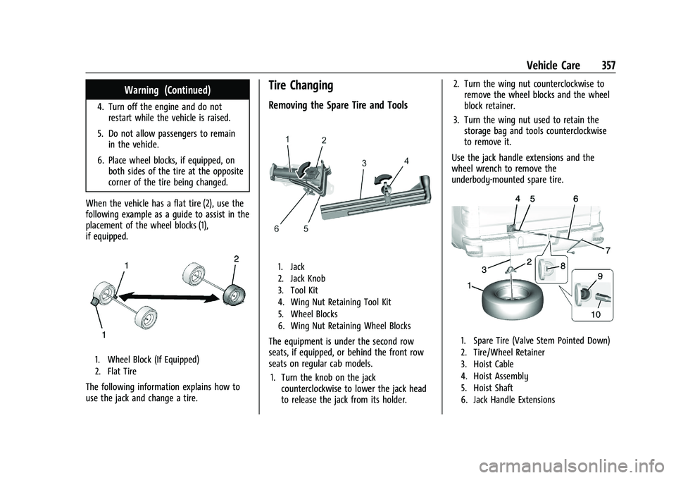
When the vehicle has a flat tire (2), use the
following example as a guide to assist in the
placement of the wheel blocks (1),
if equipped.
1. Wheel Block (If Equipped)
2. Flat Tire
The following information explains how to
use the jack and change a tire.
Tire Changing
Removing the Spare Tire and Tools
1. Jack
2. Jack Knob
3. Tool Kit
4. Wing Nut Retaining Tool Kit
5. Wheel Blocks
6. Wing Nut Retaining Wheel Blocks
The equipment is under the second row
seats, if equipped, or behind the front row
seats on regular cab models. 1. Turn the knob on the jack counterclockwise to lower the jack head
to release the jack from its holder. 2. Turn the wing nut counterclockwise to
remove the wheel blocks and the wheel
block retainer.
3. Turn the wing nut used to retain the storage bag and tools counterclockwise
to remove it.
Use the jack handle extensions and the
wheel wrench to remove the
underbody-mounted spare tire.1. Spare Tire (Valve Stem Pointed Down)
2. Tire/Wheel Retainer
3. Hoist Cable
4. Hoist Assembly
5. Hoist Shaft
6. Jack Handle Extensions
Page 369 of 430

GMC Sierra/Sierra Denali 2500 HD/3500 HD Owner Manual (GMNA-
Localizing-U.S./Canada-16504257) - 2023 - CRC - 5/18/22
368 Vehicle Care
Warning (Continued)
If you do not follow these steps exactly,
some or all of these things can hurt you.
Caution
Ignoring these steps could result in costly
damage to the vehicle that would not be
covered by the vehicle warranty. Trying
to start the vehicle by pushing or pulling
it will not work, and it could damage the
vehicle.
Caution
If the jumper cables are connected or
removed in the wrong order, electrical
shorting may occur and damage the
vehicle. The repairs would not be covered
by the vehicle warranty. Always connect
and remove the jumper cables in the
correct order, making sure that the cables
do not touch each other or other metal.
Connection Points and Sequence
1. Discharged Battery Positive (+)Terminal
2. Good Battery Positive (+) Terminal
3. Good Battery Negative (−) Terminal
4. Discharged Battery Negative Grounding (−) Terminal
The good battery positive (+) terminal and
the good battery negative (–) terminal are
on the battery of the vehicle providing the
jump start.
The discharged battery positive (+) terminal
and the discharged battery negative (–)
grounding point are on the passenger side
of the vehicle. The discharged battery positive (+) terminal
is under a cover. Open the cover to expose
the terminal.
1. Check the other vehicle. It must have a 12-volt battery with a negative ground
system.
Caution
If the other vehicle does not have a
12-volt system with a negative ground,
both vehicles can be damaged. Only use
a vehicle that has a 12-volt system with a
negative ground for jump starting.
2. If you have a vehicle with a diesel engine with two batteries, you should
know before you begin that, especially in
cold weather, you may not be able to
get enough power from a single battery
in another vehicle to start your diesel
engine. If your vehicle has more than
one battery, using the battery that is
closer to the starter will reduce electrical
resistance. This is located on the
passenger side, in the rear of the engine
compartment.
3. Get the vehicles close enough so the jumper cables can reach, but be sure the
vehicles are not touching each other.
Page 370 of 430

GMC Sierra/Sierra Denali 2500 HD/3500 HD Owner Manual (GMNA-
Localizing-U.S./Canada-16504257) - 2023 - CRC - 5/18/22
Vehicle Care 369
If they are, it could cause an unwanted
ground connection. You would not be
able to start your vehicle, and the bad
grounding could damage the electrical
systems.
To avoid the possibility of the vehicles
rolling, set the parking brake firmly on
both vehicles involved in the jump start
procedure. Put the automatic
transmission in P (Park) before setting
the parking brake. If you have a
four-wheel-drive vehicle, be sure the
transfer case is in a drive gear, not in
N (Neutral).
Caution
If any accessories are left on or plugged
in during the jump starting procedure,
they could be damaged. The repairs
would not be covered by the vehicle
warranty. Whenever possible, turn off or
unplug all accessories on either vehicle
when jump starting.
4. Turn the ignition off on both vehicles. Unplug unnecessary accessories plugged
into the accessory power outlets. Turn
off the radio and all the lamps that are not needed. This will avoid sparks and
help save both batteries. And it could
save the radio!
5. Open the hood on the other vehicle and locate the positive (+) and negative (−)
terminal locations on that vehicle.
{Warning
An electric fan can start up even when
the engine is not running and can injure
you. Keep hands, clothing, and tools
away from any underhood electric fan.
{Warning
Using a match near a battery can cause
battery gas to explode. People have been
hurt doing this, and some have been
blinded. Use a flashlight if you need
more light.
Battery fluid contains acid that can burn
you. Do not get it on you. If you
accidentally get it in your eyes or on
your skin, flush the place with water and
get medical help immediately.
{Warning
Fans or other moving engine parts can
injure you badly. Keep your hands away
from moving parts once the engine is
running.
6. Check that the jumper cables do not have loose or missing insulation. If they
do, you could get a shock. The vehicles
could be damaged too.
Before you connect the cables, here are
some basic things you should know.
Positive (+) will go to positive (+) or to a
remote positive (+) terminal if the
vehicle has one. Negative (–) will go to a
heavy, unpainted metal engine part or to
a remote negative (–) terminal if the
vehicle has one.
Do not connect positive (+) to negative
(–) or you will get a short that would
damage the battery and maybe other
parts too. And do not connect the
negative (–) cable to the negative (–)
terminal on the dead battery because
this can cause sparks.
7. Connect one end of the red positive (+) cable to the discharged battery
positive (+) terminal.
Page 371 of 430

GMC Sierra/Sierra Denali 2500 HD/3500 HD Owner Manual (GMNA-
Localizing-U.S./Canada-16504257) - 2023 - CRC - 5/18/22
370 Vehicle Care
8. Do not let the other end touch metal.Connect it to the good battery
positive (+) terminal. Use a remote
positive (+) terminal if the vehicle
has one.
9. Connect one end of the black negative (–) cable to the good battery negative
(–) terminal. Use a remote negative (–)
terminal if the vehicle has one.
Do not let the other end touch anything
until the next step.
10. Connect the other end of the negative (–) cable to the discharged battery
negative (–) grounding point.
11. Start the vehicle with the good battery and run the engine for a while.
12. Try to start the vehicle that had the dead battery. If it will not start after a
few tries, it probably needs service.
Jumper Cable Removal
Reverse the sequence exactly when
removing the jumper cables.
After starting the disabled vehicle and
removing the jumper cables, allow it to idle
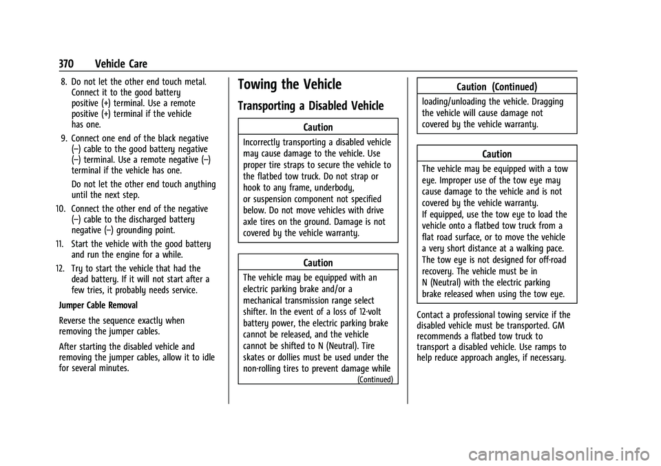
for several minutes.Towing the Vehicle
Transporting a Disabled Vehicle
Caution
Incorrectly transporting a disabled vehicle
may cause damage to the vehicle. Use
proper tire straps to secure the vehicle to
the flatbed tow truck. Do not strap or
hook to any frame, underbody,
or suspension component not specified
below. Do not move vehicles with drive
axle tires on the ground. Damage is not
covered by the vehicle warranty.
Caution
The vehicle may be equipped with an
electric parking brake and/or a
mechanical transmission range select
shifter. In the event of a loss of 12-volt
battery power, the electric parking brake
cannot be released, and the vehicle
cannot be shifted to N (Neutral). Tire
skates or dollies must be used under the
non-rolling tires to prevent damage while
(Continued)
Caution (Continued)
loading/unloading the vehicle. Dragging
the vehicle will cause damage not
covered by the vehicle warranty.
Caution
The vehicle may be equipped with a tow
eye. Improper use of the tow eye may
cause damage to the vehicle and is not
covered by the vehicle warranty.
If equipped, use the tow eye to load the
vehicle onto a flatbed tow truck from a
flat road surface, or to move the vehicle
a very short distance at a walking pace.
The tow eye is not designed for off-road
recovery. The vehicle must be in
N (Neutral) with the electric parking
brake released when using the tow eye.
Contact a professional towing service if the
disabled vehicle must be transported. GM
recommends a flatbed tow truck to
transport a disabled vehicle. Use ramps to
help reduce approach angles, if necessary.