2023 FORD F650/750 display
[x] Cancel search: displayPage 174 of 378

Radar Troubleshooting
Action Cause
Clean the grille surface in front of the radar
or remove the object causing the obstruc-
tion. The surface of the radar in the grille is dirty
or obstructed in some way.
Wait a short time. It may take several
minutes for the radar to detect that there
is no obstruction. The surface of the radar in the grille is clean
but the message remains in the display
screen.
The Pre-Collision Assist system is tempor-
arily disabled. Pre-Collision Assist automat-
ically reactivates a short time after the
weather conditions improve. Heavy rain, spray, snow or fog is interfering
with the radar signals.
The Pre-Collision Assist system is tempor-
arily disabled. Pre-Collision Assist automat-
ically reactivates a short time after the
weather conditions improve. Swirling water or snow or ice on the surface
of the road may interfere with the radar
signals.
Contact an authorized dealer to have the
radar checked for proper coverage and
operation. Radar is out of alignment due to a front end
impact.
Note:If something hits the front end of your
vehicle or damage occurs and your vehicle
has a radar sensor, the radar sensing zone
may change. This could cause missed or
false vehicle detections. Contact an
authorized dealer to have the radar checked
for proper coverage and operation.
PRE-COLLISION ASSIST -
VEHICLES WITH: HYDRAULIC
BRAKES
(IF EQUIPPED)
WARNING: You are responsible for
controlling your vehicle at all times. The
system is designed to be an aid and does
not relieve you of your responsibility to
drive with due care and attention. Failure
to follow this instruction could result in
the loss of control of your vehicle,
personal injury or death.
170
Driving Aids
Page 176 of 378

Brake Support: The system is designed
to help reduce the impact speed by
preparing the brakes for rapid braking. The
system does not automatically apply the
brakes. If you press the brake pedal, the
system could apply additional braking up
to maximum braking force, even if you
lightly press the brake pedal.
Active Braking: Active braking may
activate if the system determines that a
collision is imminent. The system may help
the driver reduce impact damage or avoid
the crash completely.
Note:If you perceive Pre-Collision Assist
alerts as being too frequent or disturbing,
then you can reduce the alert sensitivity,
though the manufacturer recommends
using the highest sensitivity setting where
possible. Setting lower sensitivity would
lead to fewer and later system warnings.
Distance Indication and Alert
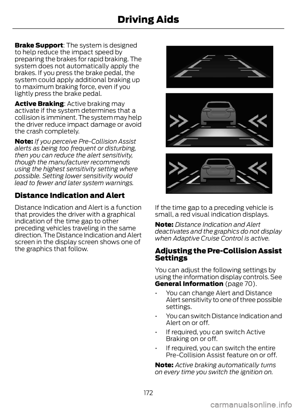
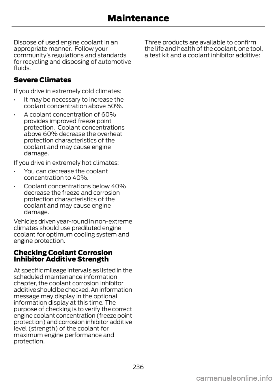
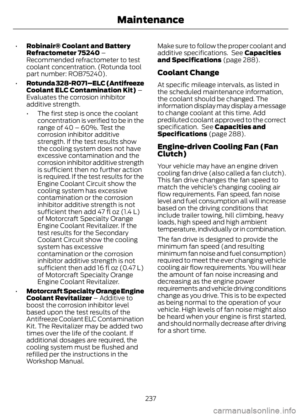
Distance Indication and Alert is a function
that provides the driver with a graphical
indication of the time gap to other
preceding vehicles traveling in the same
direction. The Distance Indication and Alert
screen in the display screen shows one of
the graphics that follow.
E254791E254791
If the time gap to a preceding vehicle is
small, a red visual indication displays.
Note:Distance Indication and Alert
deactivates and the graphics do not display
when Adaptive Cruise Control is active.
Adjusting the Pre-Collision Assist
Settings
You can adjust the following settings by
using the information display controls. See
General Information (page 70).
• You can change Alert and Distance
Alert sensitivity to one of three possible
settings.
• You can switch Distance Indication and
Alert on or off.
• If required, you can switch Active
Braking on or off.
• If required, you can switch the entire
Pre-Collision Assist feature on or off.
Note:Active braking automatically turns
on every time you switch the ignition on.
172
Driving Aids
Page 177 of 378

Note:We recommend that you switch the
system off if you install a snow plow or
similar object in such a way that it may
block the radar sensor. Your vehicle
remembers the selected setting across key
cycles.
Blocked Sensors
E31E3118731873
Camera 1
Radar sensor 2If a message regarding a blocked sensor
or camera appears in the information
display, the radar signals or camera images
are obstructed. With a blocked sensor or
camera, the Pre-Collision Assist system
may not function, or performance may
reduce. The following table lists possible
causes and actions for when this message
displays.
Camera Troubleshooting
Action Cause
Clean the outside of the windshield in front
of the camera. The windshield in front of the camera is
dirty or obstructed in some way.
Wait a short time. It may take several
minutes for the camera to detect that there
is no obstruction. The windshield in front of the camera is
clean but the message remains in the
display screen.
173
Driving Aids
Page 178 of 378

Radar Troubleshooting
Action Cause
Clean the grille surface in front of the radar
or remove the object causing the obstruc-
tion. The surface of the radar in the grille is dirty
or obstructed in some way.
Wait a short time. It may take several
minutes for the radar to detect that there
is no obstruction. The surface of the radar in the grille is clean
but the message remains in the display
screen.
The Pre-Collision Assist system is tempor-
arily disabled. Pre-Collision Assist automat-
ically reactivates a short time after the
weather conditions improve. Heavy rain, spray, snow or fog is interfering
with the radar signals.
The Pre-Collision Assist system is tempor-
arily disabled. Pre-Collision Assist automat-
ically reactivates a short time after the
weather conditions improve. Swirling water or snow or ice on the surface
of the road may interfere with the radar
signals.
Contact an authorized dealer to have the
radar checked for proper coverage and
operation. Radar is out of alignment due to a front end
impact.
Note:Proper system operation requires a
clear view of the road by the camera. Have
any windshield damage in the area of the
camera's field of view repaired.
Note:If something hits the front end of your
vehicle or damage occurs and your vehicle
has a radar sensor, the radar sensing zone
may change. This could cause missed or
false vehicle detections. Contact an
authorized dealer to have the radar checked
for proper coverage and operation.
Note:If your vehicle detects excessive heat
at the camera or a potential misalignment
condition, a message may display in the
information display indicating temporary
sensor unavailability. When operational
conditions are correct, the message
deactivates. For example, when the ambient
temperature around the sensor decreases
or the sensor automatically recalibrates
successfully.
174
Driving Aids
Page 230 of 378

3. Add engine oil that meets our
specifications. See Capacities and
Specifications (page 288).
4. Reinstall the engine oil filler cap. Turn
it clockwise until you feel a strong
resistance.
Note: Do not add oil further than the
maximum mark. Oil levels above the
maximum mark may cause engine damage.
Note:Immediately soak up any oil spillage
with an absorbent cloth.
Engine Oil Pressure Warning Lamp
WARNING: If it illuminates when
you are driving do not continue your
journey, even if the oil level is correct.
Have your vehicle checked.
It illuminates when you switch
the ignition on.
If it illuminates when the engine
is running this indicates a malfunction.
Stop your vehicle as soon as it is safe to
do so and switch the engine off. Check the
engine oil level. If the oil level is sufficient,
this indicates a system malfunction. Have
your vehicle checked as soon as possible.
CHANGING THE ENGINE OIL
AND OIL FILTER
WARNING: Do not add engine oil
when the engine is hot. Failure to follow
this instruction could result in personal
injury.If your vehicle has a diesel engine, an
Intelligent Oil Life Monitor™ calculates the
proper oil change service interval. When
the information display indicates: OIL
CHANGE REQUIRED, change the engine
oil and oil filter. See Information
Displays (page 70).
The engine oil filter protects your engine
by filtering harmful, abrasive or sludge
particles and particles significantly smaller
than most available will-fit filters. See
Motorcraft Parts (page 290).
1. Unscrew the oil filter and oil pan drain
plug and wait for the oil to drain.
2. Replace the filter.
3. Reinstall the oil pan drain plug.
4. Refill the engine with new oil. See
Engine Oil Capacity and
Specification (page 295).
5. For diesel engines, you need to reset
the Intelligent Oil Life Monitor™. See
Information Displays (page 70).
Engine Lubrication for Severe
Service Operation
The following conditions define severe
operation:
• Frequent or extended idling such as
over 10 minutes per hour of normal
driving.
• Low-speed operation or stationary use.
• If the vehicle is operated in sustained,
ambient temperatures below -9°F
(-23°C) or above 100°F (38°C).
• Frequent low-speed operation, or
consistent heavy traffic less than
25 mph (40 km/h).
• Operating in severe dust conditions.
• Operating the vehicle off road.
• Towing a trailer over 1,000 mi
(1,600 km).
226
Maintenance
Page 231 of 378

• Sustained, high-speed driving at the
gross vehicle weight rating.
• Use of fuels with sulfur content other
than ultra-low sulfur diesel (ULSD).
• Use of high-sulfur diesel fuel.
Only use engine oil that meets our
specifications. See Capacities and
Specifications (page 288).
OIL CHANGE INDICATOR
RESET
Base Cluster
Use the information display controls on
the steering wheel to reset the oil change
indicator.
From the main menu scroll to:
Action and Description Message
Press the right arrow button,
then from this menu scroll
to the following message. Settings
Press the down arrow
button, then from this menu
scroll to the following
message. Vehicle
Press the right arrow button,
then from this menu scroll
to the following message. Oil Life
Reset
Press and hold the OK
button until the instrument
cluster displays the
following message. Oil Life
Hold to
Reset
Press and hold the OK
button until the instrument
cluster displays the
following message. Oil Life
Hold OK
to Reset
Action and Description Message
Reset Complete
If the instrument cluster
displays the following
message, repeat the
process.
Reset Cancelled
High Series Cluster
Use the information display controls on
the steering wheel to reset the oil change
indicator.
From the main menu scroll to:
Action and Description Message
Press the down arrow
button, then from this menu
scroll to the following
message. Truck Info
Press the OK button. Mainten-
ance
Monitor
Press the down arrow
button, then from this menu
scroll to the following
message. Oil Life:
xxx%
Press the OK button. Oil Life
Press and hold the OK
button until the instrument
cluster displays the
following message. Oil Life
Hold OK to
Reset
Oil Life: 100%
When the oil change indic-
ator resets, the instrument
cluster displays 100%.
Repeat the process if the oil
change indicator does not
reset.
227
Maintenance
Page 240 of 378

Dispose of used engine coolant in an
appropriate manner. Follow your
community’s regulations and standards
for recycling and disposing of automotive
fluids.
Severe Climates
If you drive in extremely cold climates:
• It may be necessary to increase the
coolant concentration above 50%.
• A coolant concentration of 60%
provides improved freeze point
protection. Coolant concentrations
above 60% decrease the overheat
protection characteristics of the
coolant and may cause engine
damage.
If you drive in extremely hot climates:
• You can decrease the coolant
concentration to 40%.
• Coolant concentrations below 40%
decrease the freeze and corrosion
protection characteristics of the
coolant and may cause engine
damage.
Vehicles driven year-round in non-extreme
climates should use prediluted engine
coolant for optimum cooling system and
engine protection.
Checking Coolant Corrosion
Inhibitor Additive Strength
At specific mileage intervals as listed in the
scheduled maintenance information
chapter, the coolant corrosion inhibitor
additive should be checked. An information
message may display in the optional
information display at this time. The
purpose of checking is to verify the correct
engine coolant concentration (freeze point
protection) and corrosion inhibitor additive
level (strength) of the coolant for
maximum engine performance and
protection.Three products are available to confirm
the life and health of the coolant, one tool,
a test kit and a coolant inhibitor additive:
236
Maintenance
Page 241 of 378

•Robinair® Coolant and Battery
Refractometer 75240 –
Recommended refractometer to test
coolant concentration. (Rotunda tool
part number: ROB75240).
•Rotunda 328-R071–ELC (Antifreeze
Coolant ELC Contamination Kit) –
Evaluates the corrosion inhibitor
additive strength.
• The first step is once the coolant
concentration is verified to be in the
range of 40 – 60%. Test the
corrosion inhibitor additive
strength. If the test results show
the cooling system does not have
excessive contamination and the
corrosion inhibitor additive strength
is sufficient then no further action
is required. If the test results for the
Engine Coolant Circuit show the
cooling system has excessive
contamination or the corrosion
inhibitor additive strength is not
sufficient then add 47 fl oz (1.4 L)
of Motorcraft Specialty Orange
Engine Coolant Revitalizer. If the
test results for the Secondary
Coolant Circuit show the cooling
system has excessive
contamination or the corrosion
inhibitor additive strength is not
sufficient then add 16 fl oz (0.47 L)
of Motorcraft Specialty Orange
Engine Coolant Revitalizer.
•Motorcraft Specialty Orange Engine
Coolant Revitalizer – Additive to
boost the corrosion inhibitor level
based upon the test results of the
Antifreeze Coolant ELC Contamination
Kit. The Revitalizer may be added two
times over the life of the coolant. If
additional dosages are required, the
cooling system must be flushed and
refilled per the instructions in the
Workshop Manual.Make sure to follow the proper coolant and
additive specifications. See Capacities
and Specifications (page 288).
Coolant Change
At specific mileage intervals, as listed in
the scheduled maintenance information,
the coolant should be changed. The
information display may display a message
to change coolant at this time. Add
prediluted coolant approved to the correct
specification. See Capacities and
Specifications (page 288).
Engine-driven Cooling Fan (Fan
Clutch)
Your vehicle may have an engine driven
cooling fan drive (also called a fan clutch).
This fan drive changes the fan speed to
match the vehicle’s changing cooling air
flow requirements. Fan speed, fan noise
level and fuel consumption all will increase
based on the driving conditions that
include trailer towing, hill climbing, heavy
loads, high speed and high ambient
temperature, individually or in combination.
The fan drive is designed to provide the
minimum fan speed (and resulting
minimum fan noise and fuel consumption)
required to meet the ever changing vehicle
cooling air flow requirements. You will hear
the amount of fan noise increasing and
decreasing as the engine power
requirements and vehicle driving conditions
change as you drive. This is to be expected
as being normal to the operation of your
vehicle. High levels of fan noise might also
be heard when your engine is first started,
and should normally decrease after driving
for a short time.
237
Maintenance