2023 FORD F650/750 fuse
[x] Cancel search: fusePage 213 of 378
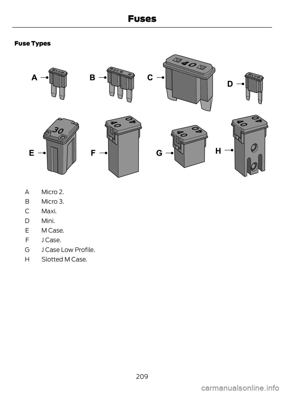
Fuse Types
E267379E267379
Micro 2. A
Micro 3. B
Maxi. C
Mini. D
M Case. E
J Case. F
J Case Low Profile. G
Slotted M Case. H
209
Fuses
Page 215 of 378
Engine compartment (with engine off)
Inspect for glazing, fraying or cracking. There should be no
more than 5-7 cracks per rib, per 1 in (2.5 cm) Belts (fan, alternator,
water pump and air
conditioning
compressor)
Inspect for signs of fluid puddles or dripping fluid on the
ground under the engine, or the underside of the engine. Fluid leaks
Inspect for debris that may have collected on the HVAC air
inlet grille or inside the exterior module as this may reduce
system performance. HVAC air inlet
Engine starting (with parking brake applied)
Before entering the cab, verify that the vehicle is equipped
with spare electrical fuses (if used), three red reflective
triangles, a properly charged and rated fire extinguisher and
wheel chocks. Safety and emergency
equipment
Walk around the vehicle and verify all steps and grab handles,
inside and out (as well as behind), are tight and clean. Use
extreme caution and a three-point stance at all times.
Inspect door latches for proper closing, latching and locking.
Set the parking brake. Make sure the gearshift lever is in
neutral (N) or park (P) (if equipped with a park position). Starting the engine
Diesel engine: Turn the key to the on position. Turn the key
to start when the wait to start indicator light in the instrument
cluster turns off.
Gasoline engine: Turn the key to start, and then release it
as soon as the engine starts.
Verify pressure builds to normal operating range. Engine oil pressure
A tone indicating low air pressure should sound immediately
after the engine starts but before the compressor has built-
up pressure. The tone should stop when the air pressure
reaches 70 psi (483 kPa). Let the air pressure build to
governed cutout pressure, which should occur between
115–130 psi (793–896 kPa). Low air pressure warning
tone (if equipped with an
air compressor)
Press the accelerator and verify that it operates smoothly,
without any binding or irregular feel. Release the pedal and
verify the engine returns to idle speed immediately. Accelerator
211
Vehicle Inspection Guide
Page 226 of 378

UNDER HOOD OVERVIEW - 6.7L DIESEL
E313700E313700
Engine compartment fuse box. See Fuses (page 200). A
Windshield washer fluid reservoir. See Washer Fluid Check (page 249). B
Automatic transmission fluid dipstick. See Automatic Transmission Fluid
Check (page 242). C
Secondary Cooling System Reservoir. See Engine Coolant Check (page 233). D
Engine coolant reservoir. See Engine Coolant Check (page 233). E
Secondary fuel filter. See Draining the Fuel Filter Water Trap (page 232). F
Engine oil separator. See Changing the Engine Oil and Oil Filter (page 226). G
Engine oil filler cap. See Engine Oil Check (page 224). H
Brake fluid reservoir. See Brake Fluid Check (page 244). I
Power steering fluid reservoir. See Power Steering Fluid Check (page 245). J
Air brake compressor. See Brake System Inspection (page 255). K
Engine oil dipstick. See Engine Oil Dipstick (page 224). L
Air cleaner assembly. See Changing the Engine Oil and Oil Filter (page 226). M
222
Maintenance
Page 227 of 378
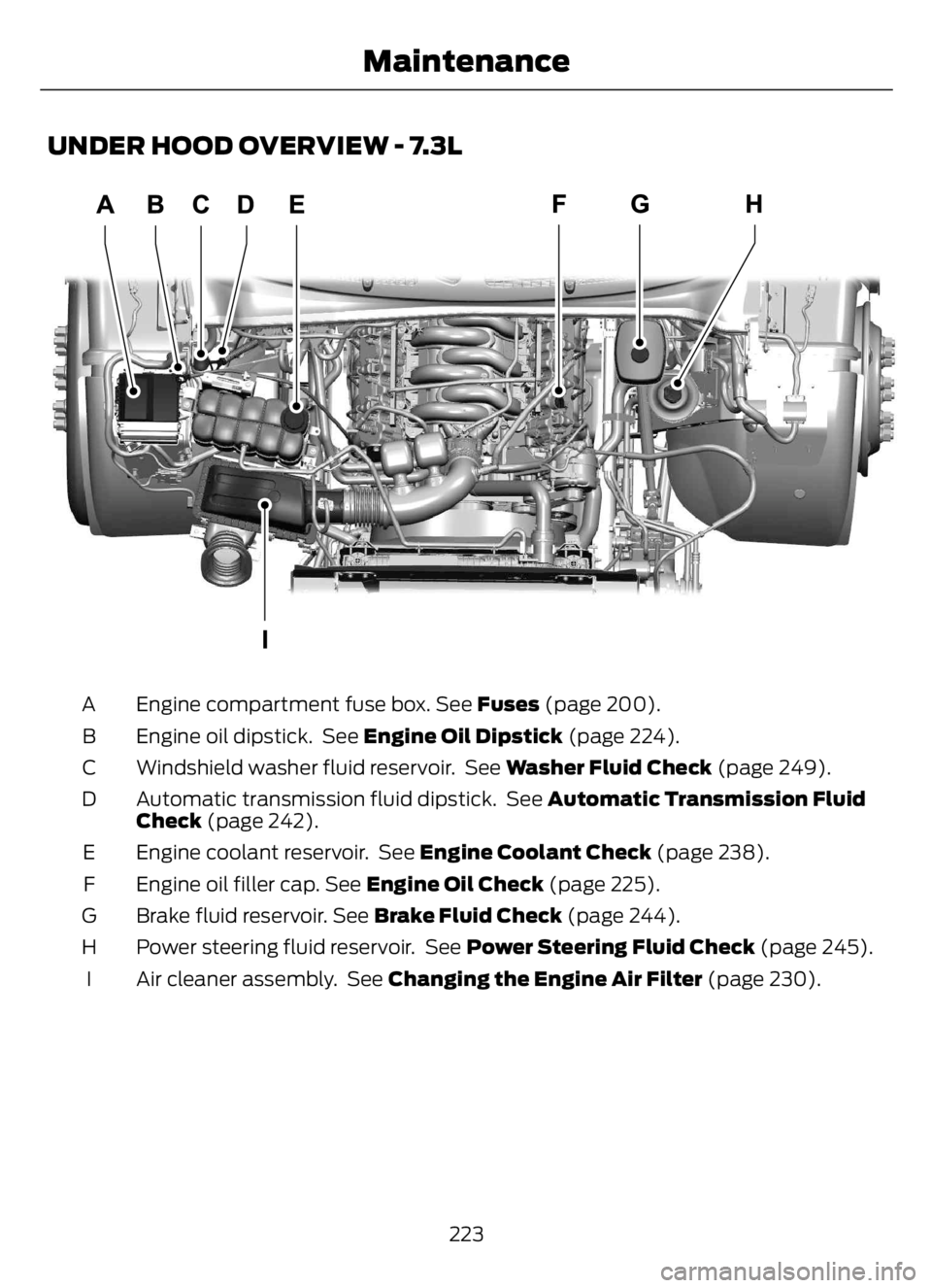
UNDER HOOD OVERVIEW - 7.3L
E330964E330964
Engine compartment fuse box. See Fuses (page 200). A
Engine oil dipstick. See Engine Oil Dipstick (page 224). B
Windshield washer fluid reservoir. See Washer Fluid Check (page 249). C
Automatic transmission fluid dipstick. See Automatic Transmission Fluid
Check (page 242). D
Engine coolant reservoir. See Engine Coolant Check (page 238). E
Engine oil filler cap. See Engine Oil Check (page 225). F
Brake fluid reservoir. See Brake Fluid Check (page 244). G
Power steering fluid reservoir. See Power Steering Fluid Check (page 245). H
Air cleaner assembly. See Changing the Engine Air Filter (page 230). I
223
Maintenance
Page 255 of 378
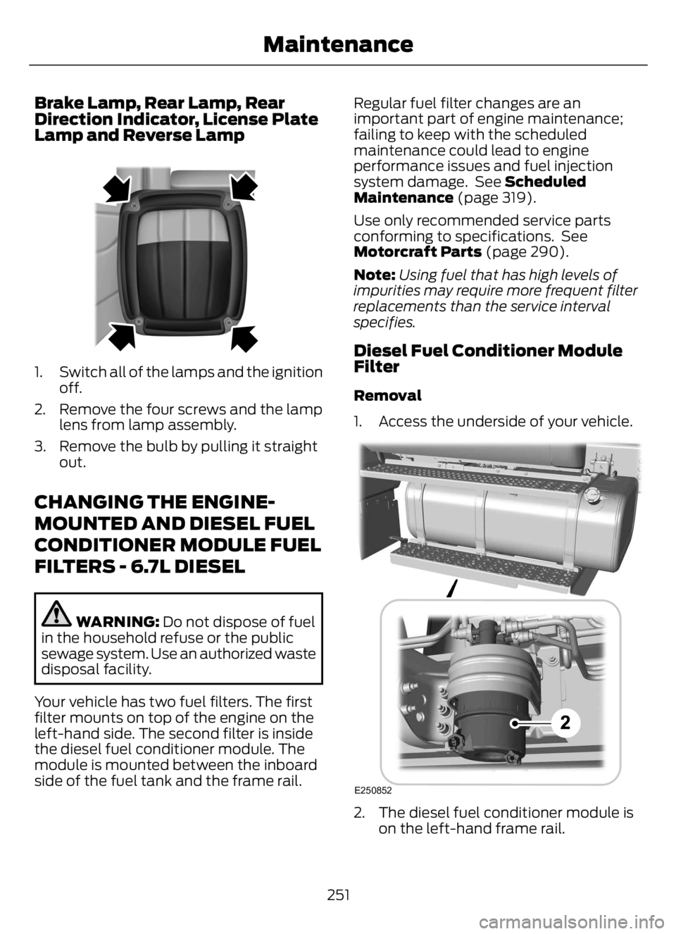
Brake Lamp, Rear Lamp, Rear
Direction Indicator, License Plate
Lamp and Reverse Lamp
E163828E163828
1. Switch all of the lamps and the ignition
off.
2. Remove the four screws and the lamp
lens from lamp assembly.
3. Remove the bulb by pulling it straight
out.
CHANGING THE ENGINE-
MOUNTED AND DIESEL FUEL
CONDITIONER MODULE FUEL
FILTERS - 6.7L DIESEL
WARNING: Do not dispose of fuel
in the household refuse or the public
sewage system. Use an authorized waste
disposal facility.
Your vehicle has two fuel filters. The first
filter mounts on top of the engine on the
left-hand side. The second filter is inside
the diesel fuel conditioner module. The
module is mounted between the inboard
side of the fuel tank and the frame rail.Regular fuel filter changes are an
important part of engine maintenance;
failing to keep with the scheduled
maintenance could lead to engine
performance issues and fuel injection
system damage. See Scheduled
Maintenance (page 319).
Use only recommended service parts
conforming to specifications. See
Motorcraft Parts (page 290).
Note:Using fuel that has high levels of
impurities may require more frequent filter
replacements than the service interval
specifies.
Diesel Fuel Conditioner Module
Filter
Removal
1. Access the underside of your vehicle.
E250852
2. The diesel fuel conditioner module is
on the left-hand frame rail.
251
Maintenance
Page 319 of 378

AUXILIARY SWITCHES (IF
EQUIPPED)
For maximum vehicle performance, keep
the following information in mind when
adding accessories or equipment to your
vehicle:
• When adding accessories, equipment,
passengers and luggage to your
vehicle, do not exceed the total weight
capacity of the vehicle or of the front
or rear axle (GVWR or GAWR as
indicated on the Safety Compliance
Certification label). Ask an authorized
dealer for specific weight information.
• The Federal Communications
Commission (FCC) and Canadian
Radio Telecommunications
Commission (CRTC) regulate the use
of mobile communications systems
equipped with radio transmitters, for
example, two-way radios, telephones
and theft alarms. Any such equipment
installed in your vehicle should comply
with Federal Communications
Commission (FCC) and Canadian
Radio Telecommunications
Commission (CRTC) regulations, and
should be installed by an authorized
dealer.
• An authorized dealer needs to install
mobile communications systems.
Improper installation may harm the
operation of your vehicle, particularly
if the manufacturer did not design the
mobile communication system
specifically for automotive use.
• If you or an authorized Ford dealer add
any non-Ford electrical or electronic
accessories or components to your
vehicle, you may adversely affect
battery performance and durability. In
addition, you may also adversely affect
the performance of other electrical
systems in the vehicle.
E163431
The auxiliary switch option package
provides four switches, mounted in the
center of the instrument panel. These
switches operate when the ignition is on
or from battery power, depending on the
switchable power distribution box fuse
locations #82 and #83. We recommend,
however, that the engine remain running
to maintain battery charge when using the
auxiliary switches for extended periods of
time or higher current draws.
Note:When your vehicle has a diesel
engine, use the auxiliary switches only while
the engine is running. The glow plugs also
drain battery power when the ignition key is
in the on position. Using the auxiliary
switches, even for limited amounts of time,
can cause your battery to drain quickly and
prevent your vehicle from restarting.
When switched on, the auxiliary switches
provide 20 amps or 40 amps of electrical
battery power for a variety of personal or
commercial uses.
The relays for the auxiliary switches are in
the power distribution box under the hood
by the right-hand fender. See your
authorized dealer for service.
Each switch includes a power lead, a
blunt-cut and sealed wire below the
instrument panel and to the left of the
steering column in the driver footwell area.
The power leads are coded as shown:
315
Accessories
Page 320 of 378

Fuse
Amp
Rating Wire
Color Circuit
Number Switch
40A Yellow CAC05 AUX 1
40A Green
with
Brown
Tr a c e CAC06 AUX 2
20A Violet
with
Green
Tr a c e CAC07 AUX 3
20A Brown CAC08 AUX 4
Learn more about auxiliary switches
by visiting:
Web Address
www.fleet.ford.com/truckbbas/
Upfitter Interface Module (If Equipped)
The Upfitter Interface Module (UIM) is an
electronic control module that operates
equipment, such as lift buckets, cranes,
motors, salt spreaders and snow plows,
with external relays.
If you replace the module, it will require
additional programming by the upfitter.
Obtain this data directly from the upfitter
company. The upfitter contact information
is in the vehicle door opening.
For more information on the Upfitter
Interface Module and the auxiliary
switches, contact your upfitter.
316
Accessories
Page 362 of 378
that any such export laws, rules or
regulations prohibit HERE from complying
with any of its obligations hereunder to
deliver or distribute Data, such failure shall
be excused and shall not constitute a
breach of this Agreement.
Entire Agreement.
These terms and conditions constitute the
entire agreement between Telenav (and
its licensors, including their licensors and
suppliers) and you pertaining to the subject
matter hereof, and supersedes in their
entirety any and all written or oral
agreements previously existing between
us with respect to such subject matter.
Governing Law.
The above terms and conditions shall be
governed by the laws of the State of Illinois
[insert “Netherlands” where European
HERE Data is used], without giving effect
to (i) its conflict of laws provisions, or (ii)
the United Nations Convention for
Contracts for the International Sale of
Goods, which is explicitly excluded. You
agree to submit to the jurisdiction of the
State of Illinois [insert “The Netherlands”
where European HERE Data is used] for
any and all disputes, claims and actions
arising from or in connection with the Data
provided to you hereunder.
Government End Users.
If the Data is being acquired by or on behalf
of the United States government or any
other entity seeking or applying rights
similar to those customarily claimed by the
United States government, this Data is a
“commercial item” as that term is defined
at 48 C.F.R. (“FAR”) 2.101, is licensed in
accordance with these End-User Terms,
and each copy of Data delivered or
otherwise furnished shall be marked and
embedded as appropriate with the
following “Notice of Use,” and shall be
treated in accordance with such Notice:
NOTICE OF USE
CONTRACTOR (MANUFACTURER/
SUPPLIER) NAME: HERE
CONTRACTOR (MANUFACTURER/
SUPPLIER) ADDRESS: c/o Nokia, 425
West Randolph Street, Chicago, Illinois
60606
This Data is a commercial item as
defined in FAR 2.101 and is subject to
these End-User Terms under which this
Data was provided.
© 1987 – 2014 HERE – All rights reserved.
If the Contracting Officer, federal
government agency, or any federal official
refuses to use the legend provided herein,
the Contracting Officer, federal
government agency, or any federal official
must notify HERE prior to seeking
additional or alternative rights in the Data.
I. US/Canada Territory
A. United States Data. The End-User
Terms for any Application containing
Data for the United States shall contain
the following notices:
“HERE holds a non-exclusive license
from the United States Postal
Service® to publish and sell ZIP+4®
information.”
“©United States Postal Service®
20XX. Prices are not established,
controlled or approved by the United
States Postal Service®. The following
trademarks and registrations are
owned by the USPS: United States
Postal Service, USPS, and ZIP+4.”
358
Appendices