2023 DODGE HORNET flat tire
[x] Cancel search: flat tirePage 212 of 288

210IN CASE OF EMERGENCY
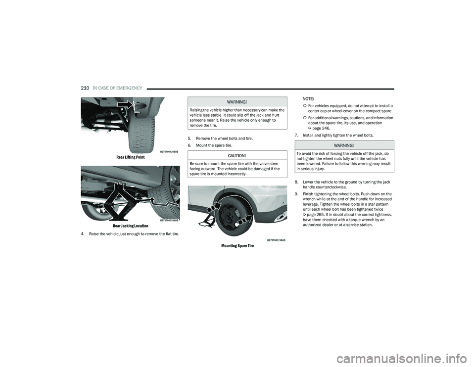
Rear Lifting Point
Rear Jacking Location
4. Raise the vehicle just enough to remove the flat tire. 5. Remove the wheel bolts and tire.
6. Mount the spare tire.
Mounting Spare Tire
NOTE:
For vehicles equipped, do not attempt to install a
center cap or wheel cover on the compact spare.
For additional warnings, cautions, and information
about the spare tire, its use, and operation
Úpage 246.
7. Install and lightly tighten the wheel bolts.
8. Lower the vehicle to the ground by turning the jack handle counterclockwise.
9. Finish tightening the wheel bolts. Push down on the wrench while at the end of the handle for increased
leverage. Tighten the wheel bolts in a star pattern
until each wheel bolt has been tightened twice
Úpage 265. If in doubt about the correct tightness,
have them checked with a torque wrench by an
authorized dealer or at a service station.
WARNING!
Raising the vehicle higher than necessary can make the
vehicle less stable. It could slip off the jack and hurt
someone near it. Raise the vehicle only enough to
remove the tire.
CAUTION!
Be sure to mount the spare tire with the valve stem
facing outward. The vehicle could be damaged if the
spare tire is mounted incorrectly.
WARNING!
To avoid the risk of forcing the vehicle off the jack, do
not tighten the wheel nuts fully until the vehicle has
been lowered. Failure to follow this warning may result
in serious injury.
23_GG_OM_EN_USC_t.book Page 210
Page 213 of 288

IN CASE OF EMERGENCY211
10. Lower the jack until it is free. Remove the wheel
blocks. Stow the wheel bolt wrench, jack assembly
and wheel blocks in the provided storage. Secure the
assembly using the means provided. Release the
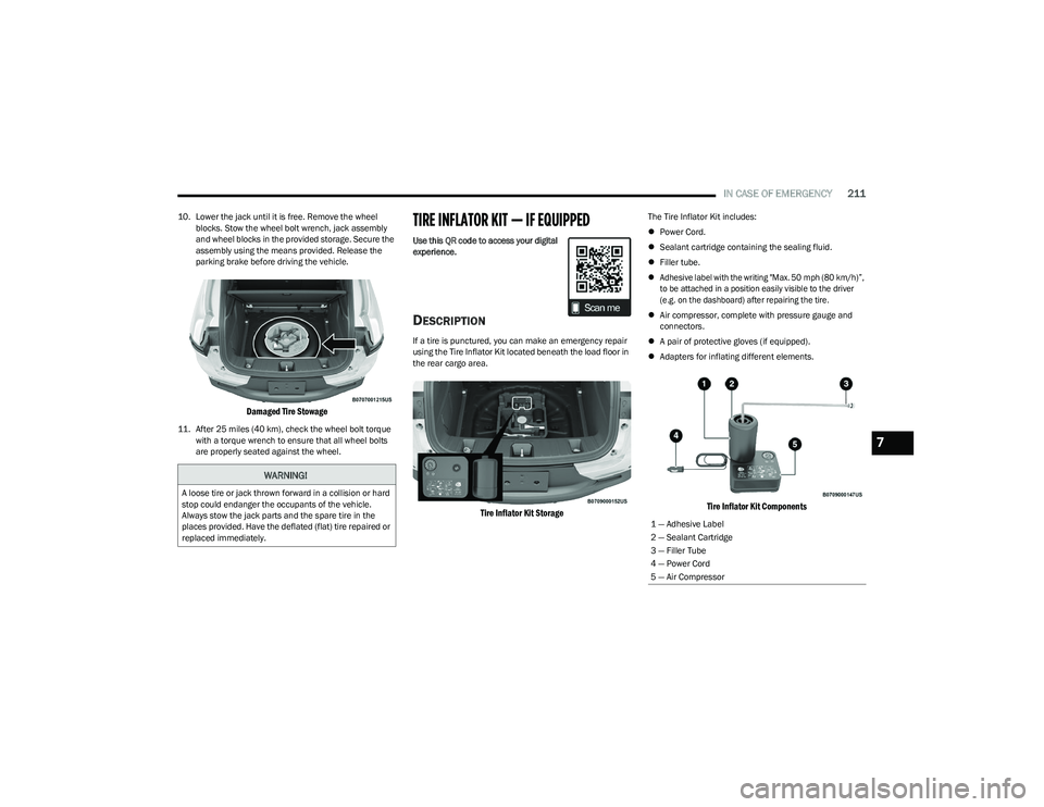
parking brake before driving the vehicle.
Damaged Tire Stowage
11. After 25 miles (40 km), check the wheel bolt torque with a torque wrench to ensure that all wheel bolts
are properly seated against the wheel.
TIRE INFLATOR KIT — IF EQUIPPED
Use this QR code to access your digital
experience.
DESCRIPTION
If a tire is punctured, you can make an emergency repair
using the Tire Inflator Kit located beneath the load floor in
the rear cargo area.
Tire Inflator Kit Storage
The Tire Inflator Kit includes:
Power Cord.
Sealant cartridge containing the sealing fluid.
Filler tube.
Adhesive label with the writing "Max. 50 mph (80 km/h)”,
to be attached in a position easily visible to the driver
(e.g. on the dashboard) after repairing the tire.
Air compressor, complete with pressure gauge and
connectors.
A pair of protective gloves (if equipped).
Adapters for inflating different elements.
Tire Inflator Kit Components
WARNING!
A loose tire or jack thrown forward in a collision or hard
stop could endanger the occupants of the vehicle.
Always stow the jack parts and the spare tire in the
places provided. Have the deflated (flat) tire repaired or
replaced immediately.
1 — Adhesive Label
2 — Sealant Cartridge
3 — Filler Tube
4 — Power Cord
5 — Air Compressor
7
23_GG_OM_EN_USC_t.book Page 211
Page 214 of 288

212IN CASE OF EMERGENCY
(Continued)
INFLATION PROCEDURENOTE:Always follow applicable state and provincial laws. Contact
state and provincial Highway Safety offices for additional
details.
To use your Tire Inflator Kit, proceed as follows:
1. Stop the vehicle in a position where you can repair
the tire safely. Activate the Hazard Warning Flashers
to make other drivers aware of your presence.
2. If equipped, use all available safety equipment required by law.
3. Verify that the valve stem (on the wheel with the deflated tire) is in a position that is near to the
ground. This will allow the Tire Inflator Kit hoses to
reach the valve stem and keep the tire repair kit flat
on the ground.
4. Place the gear selector to PARK (P).
5. Apply the Electric Park Brake and cycle the engine OFF.
6. Insert the sealant cartridge containing the sealing fluid in the proper compressor holder, pushing down
hard. Unscrew the tire valve cap, take out the filler
tube and tighten the fitting on the tire valve.
WARNING!
The information required by current legislation is
shown on the kit cartridge label. Read the cartridge
label before use, avoid improper use.
Do not attempt to seal a tire on the side of the
vehicle closest to traffic. Pull far enough off the
road to avoid the danger of being hit when using
the Tire Service Kit.
Do not remove foreign bodies from the tire.
Do not leave the compressor running for more than
20 minutes, this may cause overheating.
Do not use the Tire Service Kit or drive the vehicle
under the following circumstances:
If the puncture in the tire tread is approximately
1/4 inch (6 mm) or larger.
If the tire has any sidewall damage.
If the tire has any damage from driving with
extremely low tire pressure.
If the tire has any damage from driving on a
flat tire.
If the wheel has any damage.
If you are unsure of the condition of the tire or
the wheel.
Keep the Tire Service Kit away from open flames or
heat sources.
A loose Tire Service Kit thrown forward in a collision
or hard stop could endanger the occupants of the
vehicle. Always stow the Tire Service Kit in the place
provided. Failure to follow these warnings can result
in injuries that are serious or fatal to you, your
passengers, and others around you.
Take care not to allow the contents of the Tire
Service Kit to come in contact with hair, eyes, or
clothing. Tire Service Kit sealant is harmful if inhaled,
swallowed, or absorbed through the skin. It causes
skin, eye, and respiratory irritation. Flush immedi -
ately with plenty of water if there is any contact with
eyes or skin. Change clothing as soon as possible, if
there is any contact with clothing.
Tire Service Kit sealant solution contains latex. In
case of an allergic reaction or rash, consult a physi -
cian immediately. Keep the Tire Service Kit out of
reach of children. If swallowed, rinse mouth immedi -
ately with plenty of water and drink plenty of water.
Do not induce vomiting! Consult a physician immedi -
ately.
WARNING!
23_GG_OM_EN_USC_t.book Page 212
Page 215 of 288

IN CASE OF EMERGENCY213
Attaching Filler Tube To Deflated Tire
7. Make sure the compressor is switched off.
8. Insert the plug into the vehicle’s center console
power outlet, then start the engine.
Power Outlet Location
9. Switch the compressor on.
10. Inflate the tire to the pressure indicated on the tire placard, located on the driver’s side B-pillar or the
rear edge of the driver’s side door
Úpage 251. In
order to obtain a more precise reading, check the
pressure value on pressure gauge with the
compressor off.
Air Compressor
11. If the pressure is not at least 26.1 psi (1.8 bar) after 15 minutes, disengage the compressor from the
valve and power outlet. Then, move the vehicle
forwards approximately 33 ft (10 m) in order to
distribute the sealant inside the tire evenly, and then
repeat the inflation operation. 12. If you still cannot obtain a pressure of at least 26 psi
(1.8 bar) within 15 minutes of turning the compressor
on, do not drive the vehicle, and contact an
authorized dealer.
13. Drive the vehicle for about 5 miles (8 km), stop, apply the Electric Park Brake, and recheck the tire
pressure.
14. If the pressure is less than 26 psi (1.8 bar), DO NOT
drive the vehicle, and see an authorized dealer.
15. If a pressure value of at least 26 psi (1.8 bar) is detected, restore the correct pressure (with engine
running and Electric Park Brake applied), and drive
immediately with great care to an authorized dealer.
2 — Sealant Cartridge
3 — Filler Tube
4 — Pressure Gauge
5 — Power Switch
WARNING!
The Tire Service Kit is not a permanent flat tire repair.
Have the tire inspected and repaired or replaced after
using the Tire Service Kit. Do not exceed 50 mph
(80 km/h) until the tire is repaired or replaced. Failure
to follow this warning can result in injuries that are
serious or fatal to you, your passengers, and others
around you. Have the tire checked as soon as possible
at an authorized dealer.
7
23_GG_OM_EN_USC_t.book Page 213
Page 216 of 288

214IN CASE OF EMERGENCY
16. Apply the adhesive label from the sealant bottle
where it can be easily seen by the driver as a
reminder that the tire has been treated with a Tire
Inflator Kit, as well as not to exceed the speed
restriction for the treated tire.
CHECKING AND RESTORING TIRE
P
RESSURE
The compressor can also be used to check and, if
necessary, restore the tire pressure.
Proceed as follows:
1. Plug the power cord in the vehicle’s power outlet.
2. Release the quick connector and connect it directly to
the valve of the tire to be inflated. 3. Push the air release button.
Air Compressor Components
SEALANT CARTRIDGE REPLACEMENT
The sealant liquid is subject to expiration and must be
replaced periodically.
Use only original cartridges, which can be purchased at
an authorized dealer.
Show the cartridge and label to the staff who will have
to handle the tire treated with the kit.
The sealant is effective with external temperatures of
between -40°F (-40°C) and 122°F (50°C).
The sealant has an expiration date.
To replace the sealant cartridge, proceed as follows:
1. Remove the sealant cartridge by pushing the release button located on the side of the
compressor.
2. Insert the new sealant cartridge by pushing downward firmly.
Sealant Cartridge Replacement
WARNING!
Do not adhere the speed restriction sticker to the
padded area on the steering wheel. Adhering the speed
restriction sticker to the padded area on the steering
wheel is dangerous because the air bag may not
operate (deploy) normally resulting in serious injury.
In addition, do not adhere the sticker to areas where
warning lights or the speedometer cannot be viewed.
6 — Air Release Button
7 — Quick Connector
8 — Power Cord
9 — Release Button
2 — Sealant Cartridge
9 — Release Button
23_GG_OM_EN_USC_t.book Page 214
Page 225 of 288

223
SERVICING AND MAINTENANCE
SCHEDULED SERVICING
Your vehicle is equipped with an automatic oil change
indicator system. The oil change indicator system will
remind you that it is time to take your vehicle in for
scheduled maintenance.
Based on engine operation conditions, the oil change
indicator message will illuminate in the instrument cluster.
This means that service is required for your vehicle.
Operating conditions such as frequent short-trips, trailer
towing, and extremely hot or cold ambient temperatures
will influence when the “Change Oil” or “Oil Change
Required” message is displayed. Have your vehicle
serviced as soon as possible, within the next 500 miles
(805 km).An authorized dealer will reset the oil change indicator
message after completing the scheduled oil change. If a
scheduled oil change is performed by someone other than
an authorized dealer, the message can be reset by
referring to the steps described under Instrument Cluster
Display
Úpage 66.
NOTE:Under no circumstances should oil change intervals
exceed 10,000 miles (16,000 km), one year or 350 hours
of engine run time, whichever comes first. The 350 hours
of engine run or idle time is generally only a concern for
fleet customers.
Once A Month Or Before A Long Trip:
Check engine oil level.
Check windshield washer fluid level.
Check the tire inflation pressures and look for unusual
wear or damage. Rotate tires at the first sign of irreg -
ular wear, even if it occurs before the oil indicator
system turns on.
Check the fluid levels of the coolant reservoir, and
brake master cylinder reservoir, and fill as needed.
Check function of all interior and exterior lights.
8
23_GG_OM_EN_USC_t.book Page 223
Page 250 of 288

248SERVICING AND MAINTENANCE
Service Description:
95 = Load Index
A numerical code associated with the maximum load a tire can carry
H = Speed Symbol
A symbol indicating the range of speeds at which a tire can carry a load corresponding to its load index under certain operating conditions
The maximum speed corresponding to the speed symbol should only be achieved under specified operating conditions (i.e., tire pressure, vehicle loading, road conditions, and
posted speed limits)
Load Identification:
Absence of the following load identification symbols on the sidewall of the tire indicates a Standard Load (SL) tire:
XL = Extra load (or reinforced) tire, or
LL = Light load tire or
C, D, E, F, G = Load range associated with the maximum load a tire can carry at a specified pressure
Maximum Load – Maximum load indicates the maximum load this tire is designed to carry
Maximum Pressure – Maximum pressure indicates the maximum permissible cold tire inflation pressure for this tire
EXAMPLE:
23_GG_OM_EN_USC_t.book Page 248
Page 252 of 288

250SERVICING AND MAINTENANCE
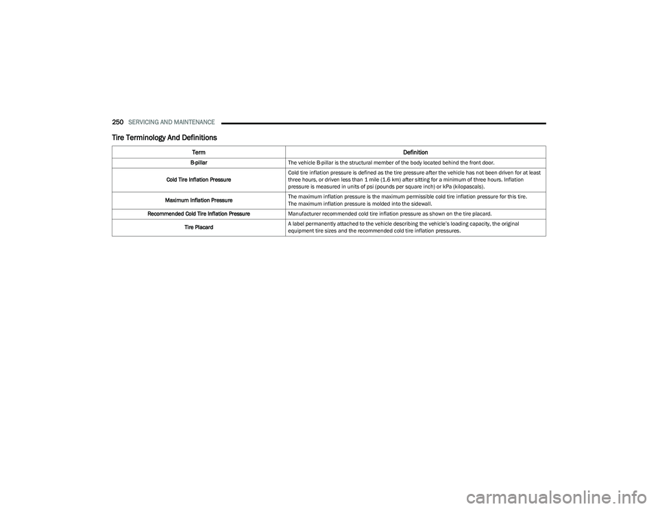
Tire Terminology And Definitions
Term Definition
B-pillarThe vehicle B-pillar is the structural member of the body located behind the front door.
Cold Tire Inflation Pressure Cold tire inflation pressure is defined as the tire pressure after the vehicle has not been driven for at least
three hours, or driven less than 1 mile (1.6 km) after sitting for a minimum of three hours. Inflation
pressure is measured in units of psi (pounds per square inch) or kPa (kilopascals).
Maximum Inflation Pressure The maximum inflation pressure is the maximum permissible cold tire inflation pressure for this tire.
The maximum inflation pressure is molded into the sidewall.
Recommended Cold Tire Inflation Pressure Manufacturer recommended cold tire inflation pressure as shown on the tire placard.
Tire Placard A label permanently attached to the vehicle describing the vehicle’s loading capacity, the original
equipment tire sizes and the recommended cold tire inflation pressures.
23_GG_OM_EN_USC_t.book Page 250