2023 DODGE CHALLENGER spare tire
[x] Cancel search: spare tirePage 207 of 300

IN CASE OF EMERGENCY205
Rear Lifting Point
Rear Jacking Location
5. Raise the vehicle just enough to remove the flat tire and install the spare tire. 6. Remove the lug nuts and tire.
7. Mount the spare tire.
Mounting Spare Tire
NOTE:For vehicles so equipped, do not attempt to install a center
cap or wheel cover on the compact spare Úpage 265.8. Install the lug nuts with the cone shaped end of the
lug nut toward the wheel. Lightly tighten the lug nuts.
9. Lower the vehicle to the ground by turning the jack handle counterclockwise.
10. Finish tightening the wheel bolts. Push down on the wrench while at the end of the handle for increased
leverage. Tighten the wheel bolts in a star pattern
until each wheel bolt has been tightened twice
Úpage 273. If in doubt about the correct tightness,
have them checked with a torque wrench by an
authorized dealer or at a service station.
11. Stow the jack, tools and flat tire. Make sure the base of the jack faces the front of the vehicle before
tightening down the fastener.
WARNING!
Raising the vehicle higher than necessary can make the
vehicle less stable. It could slip off the jack and hurt
someone near it. Raise the vehicle only enough to
remove the tire.
CAUTION!
Be sure to mount the spare tire with the valve stem
facing outward. The vehicle could be damaged if the
spare tire is mounted incorrectly.
WARNING!
To avoid the risk of forcing the vehicle off the jack, do
not tighten the wheel nuts fully until the vehicle has
been lowered. Failure to follow this warning may result
in serious injury.
WARNING!
A loose tire or jack thrown forward in a collision or hard
stop could endanger the occupants of the vehicle.
Always stow the jack parts and the spare tire in the
places provided. Have the deflated (flat) tire repaired or
replaced immediately.
7
23_LA_OM_EN_USC_t.book Page 205
Page 248 of 300

246SERVICING AND MAINTENANCE
Rear Fuses
There is also a power distribution center located in the
trunk under the spare tire access panel. This center
contains fuses and relays. Fuse cavity location and
descriptions are printed on the inside of the power
distribution center cover.
Rear Power Distribution Center Location
CAUTION!
When installing the power distribution center cover, it is
important to ensure the cover is properly positioned
and fully latched. Failure to do so may allow water to get
into the power distribution center and possibly result in
an electrical system failure.
CavityCartridge Fuse Mini-FuseDescription
* If Equipped
F02 60 Amp Yellow –Front PDC Feed #1
F03 ––Spare
F04 60 Amp Yellow –Front PDC Feed #2
F05 30 Amp Pink
–Sunroof *
20 Amp Blue – Police Dome Lamp – Police
F06 40 Amp Green –Exterior Lighting #1
F07 40 Amp Green –Exterior Lighting #2
F08 30 Amp Pink –Interior Lighting
F09 40 Amp Green –Power Locks
F10 30 Amp Pink –Driver Door Control Module
F11 30 Amp Pink –Passenger Door Control Module
F12 –20 Amp YellowCigar Lighter / IP APO / RR USB
(Selectable Fuse) *
23_LA_OM_EN_USC_t.book Page 246
Page 249 of 300

SERVICING AND MAINTENANCE247
F15 40 Amp Green –HVAC Blower
F16 20 Amp Blue –Left Spot Lamp – Police
F17 20 Amp Blue –Right Spot Lamp – Police
F18 30 Amp Pink –VISM Mod (Police)
F19 ––Spare
F20 ––Spare
F21 30 Amp Pink
–Fuel Pump (Non 6.2L ADR)
40 Amp Green Fuel Pump #2 (6.2L XVC)
F22 –5 Amp TanCyber Gateway Module
F23 –10 Amp RedFuel Door SW * / Diagnostic Port
F24 –10 Amp RedIntegrated Center Stack
F25 –10 Amp RedTire Pressure Monitor System
F26 –15 Amp BlueTrans Mod (Charger / 300)
F27 –25 Amp ClearAmplifier *
F31 –25 Amp BreakerPower Seats *
F32 –15 Amp BlueHVAC Module / Cluster
F33 –15 Amp BlueIGN SW / Wireless Mod / Steer Clmn Lock
Mod / Remote Start *
F34 –10 Amp RedSteering Column Module / Clock (300)
F35 –5 Amp TanBattery Sensor
F36 –15 Amp BlueActive Exhaust Valve *
F37 –20 Amp YellowRadio
Cavity Cartridge Fuse Mini-FuseDescription
* If Equipped
8
23_LA_OM_EN_USC_t.book Page 247
Page 256 of 300

254SERVICING AND MAINTENANCE
Tire Markings
Tire Markings
NOTE:
P (Passenger) — Metric tire sizing is based on US design
standards. P-Metric tires have the letter “P” molded
into the sidewall preceding the size designation.
Example: P215/65R15 95H.
European — Metric tire sizing is based on European
design standards. Tires designed to this standard have
the tire size molded into the sidewall beginning with the
section width. The letter "P" is absent from this tire size
designation.
Example: 215/65R15 96H.
LT (Light Truck) — Metric tire sizing is based on US
design standards. The size designation for LT-Metric
tires is the same as for P-Metric tires except for the
letters “LT” that are molded into the sidewall preceding
the size designation.
Example: LT235/85R16.
Temporary spare tires are designed for temporary
emergency use only. Temporary high pressure compact
spare tires have the letter “T” or “S” molded into the
sidewall preceding the size designation.
Example: T145/80D18 103M.
High flotation tire sizing is based on US design stan -
dards and it begins with the tire diameter molded into
the sidewall.
Example: 31x10.5 R15 LT.
1 — US DOT Safety Standards Code
(TIN)
2 — Size Designation
3 — Service Description
4 — Maximum Load
5 — Maximum Pressure
6 — Treadwear, Traction and
Temperature Grades
23_LA_OM_EN_USC_t.book Page 254
Page 257 of 300

SERVICING AND MAINTENANCE255
TIRE SIZING CHART
EXAMPLE:
Example Size Designation: P215/65R15XL 95H, 215/65R15 96H, LT235/85R16C, T145/80D18 103M, 31x10.5 R15 LT
P = Passenger car tire size based on US design standards, or
"....blank...." = Passenger car tire based on European design standards, or
LT = Light truck tire based on US design standards, or
T or S = Temporary spare tire or
31 = Overall diameter in inches (in)
215, 235, 145 = Section width in millimeters (mm)
65, 85, 80 = Aspect ratio in percent (%)
Ratio of section height to section width of tire, or
10.5 = Section width in inches (in)
R = Construction code
"R" means radial construction, or
"D" means diagonal or bias construction
15, 16, 18 = Rim diameter in inches (in)
8
23_LA_OM_EN_USC_t.book Page 255
Page 260 of 300

258SERVICING AND MAINTENANCE
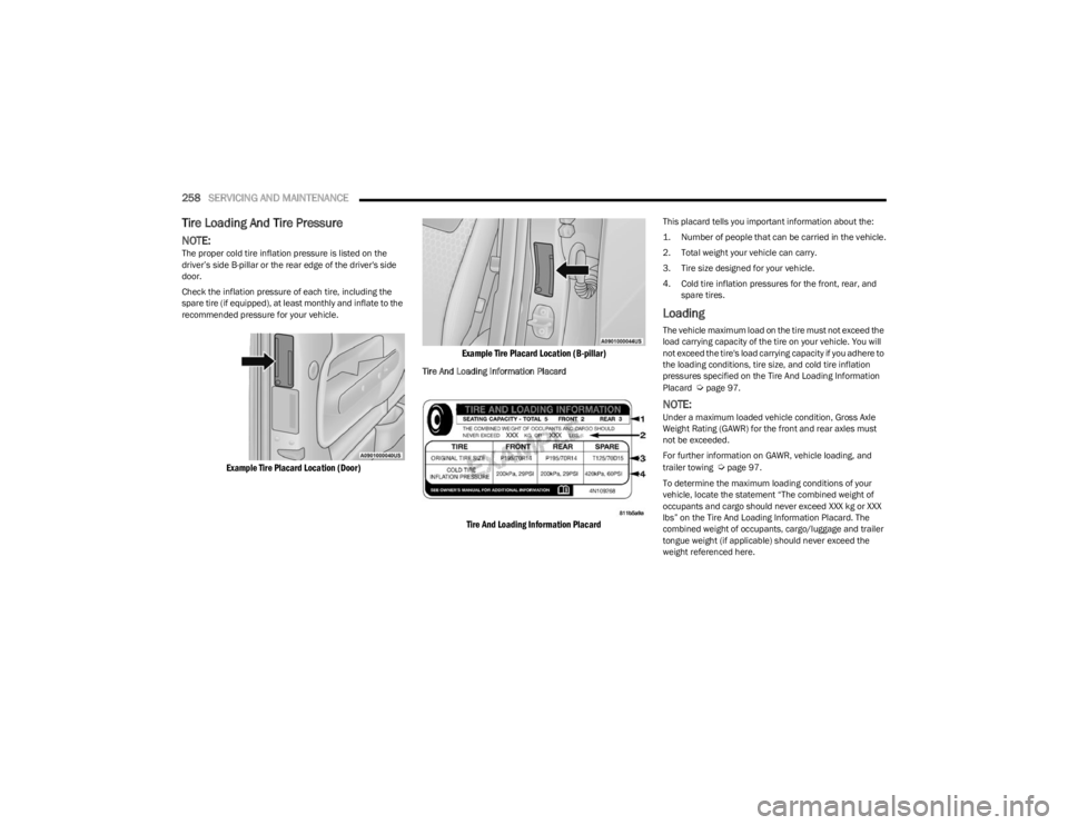
Tire Loading And Tire Pressure
NOTE:The proper cold tire inflation pressure is listed on the
driver’s side B-pillar or the rear edge of the driver's side
door.
Check the inflation pressure of each tire, including the
spare tire (if equipped), at least monthly and inflate to the
recommended pressure for your vehicle.
Example Tire Placard Location (Door) Example Tire Placard Location (B-pillar)
Tire And Loading Information Placard
Tire And Loading Information Placard
This placard tells you important information about the:
1. Number of people that can be carried in the vehicle.
2. Total weight your vehicle can carry.
3. Tire size designed for your vehicle.
4. Cold tire inflation pressures for the front, rear, and
spare tires.
Loading
The vehicle maximum load on the tire must not exceed the
load carrying capacity of the tire on your vehicle. You will
not exceed the tire's load carrying capacity if you adhere to
the loading conditions, tire size, and cold tire inflation
pressures specified on the Tire And Loading Information
Placard
Úpage 97.
NOTE:Under a maximum loaded vehicle condition, Gross Axle
Weight Rating (GAWR) for the front and rear axles must
not be exceeded.
For further information on GAWR, vehicle loading, and
trailer towing
Úpage 97.
To determine the maximum loading conditions of your
vehicle, locate the statement “The combined weight of
occupants and cargo should never exceed XXX kg or XXX
lbs” on the Tire And Loading Information Placard. The
combined weight of occupants, cargo/luggage and trailer
tongue weight (if applicable) should never exceed the
weight referenced here.
23_LA_OM_EN_USC_t.book Page 258
Page 265 of 300

SERVICING AND MAINTENANCE263
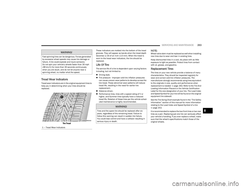
Tread Wear Indicators
Tread wear indicators are in the original equipment tires to
help you in determining when your tires should be
replaced.
Tire Tread
These indicators are molded into the bottom of the tread
grooves. They will appear as bands when the tread depth
becomes 1/16 of an inch (1.6 mm). When the tread is
worn to the tread wear indicators, the tire should be
replaced.
Life Of Tire
The service life of a tire is dependent upon varying factors
including, but not limited to:
Driving style.
Tire pressure - Improper cold tire inflation pressures
can cause uneven wear patterns to develop across the
tire tread. These abnormal wear patterns will reduce
tread life, resulting in the need for earlier tire
replacement.
Distance driven.
Performance tires, tires with a speed rating of V or
higher, and Summer tires typically have a reduced
tread life. Rotation of these tires per the vehicle sched-
uled maintenance is highly recommended.
NOTE:Wheel valve stem must be replaced as well when installing
new tires due to wear and tear in existing tires.
Keep dismounted tires in a cool, dry place with as little
exposure to light as possible. Protect tires from contact
with oil, grease, and gasoline.
Replacement Tires
The tires on your new vehicle provide a balance of many
characteristics. They should be inspected regularly for
wear and correct cold tire inflation pressures. The
manufacturer strongly recommends using tires equivalent
to the originals in size, quality and performance when
replacement is needed
Úpage 263. Refer to the Tire And
Loading Information Placard or the Vehicle Certification
Label for the size designation of your tire. The Load Index
and Speed Symbol for your tire will be found on the original
equipment tire sidewall.
See the Tire Sizing Chart example found in the “Tire Safety
Information” section of this manual for more information
relating to the Load Index and Speed Symbol of a tire
Úpage 253.
It is recommended to replace the two front tires or two rear
tires as a pair. Replacing just one tire can seriously affect
your vehicle’s handling. If you ever replace a wheel, make
sure that the wheel’s specifications match those of the
original wheels.
WARNING!
Fast spinning tires can be dangerous. Forces generated
by excessive wheel speeds may cause tire damage or
failure. A tire could explode and injure someone.
Do not spin your vehicle's wheels faster than 30 mph
(48 km/h) for more than 30 seconds continuously
when you are stuck, and do not let anyone near a
spinning wheel, no matter what the speed.
1 — Tread Wear Indicators
WARNING!
Tires and the spare tire should be replaced after six
years, regardless of the remaining tread. Failure to
follow this warning can result in sudden tire failure.
You could lose control and have a collision resulting in
serious injury or death.8
23_LA_OM_EN_USC_t.book Page 263
Page 266 of 300

264SERVICING AND MAINTENANCE
It is recommended you contact an authorized tire dealer or
original equipment dealer with any questions you may
have on tire specifications or capability. Failure to use
equivalent replacement tires may adversely affect the
safety, handling, and ride of your vehicle.TIRE TYPES
All Season Tires — If Equipped
All Season tires provide traction for all seasons (Spring,
Summer, Autumn, and Winter). Traction levels may vary
between different all season tires. All season tires can be
identified by the M+S, M&S, M/S or MS designation on the
tire sidewall. Use all season tires only in sets of four;
failure to do so may adversely affect the safety and
handling of your vehicle.
Summer Or Three Season Tires —
If Equipped
Summer tires provide traction in both wet and dry
conditions, and are not intended to be driven in snow or on
ice. If your vehicle is equipped with Summer tires, be
aware these tires are not designed for Winter or cold
driving conditions. Install Winter tires on your vehicle when
ambient temperatures are less than 40°F (5°C) or if
roads are covered with ice or snow. For more information,
contact an authorized dealer.
Summer tires do not contain the all season designation or
mountain/snowflake symbol on the tire sidewall. Use
Summer tires only in sets of four; failure to do so may
adversely affect the safety and handling of your vehicle.
Snow Tires
Some areas of the country require the use of snow tires
during the Winter. Snow tires can be identified by a
mountain/snowflake symbol on the tire sidewall.
If you need snow tires, select tires equivalent in
size and type to the original equipment tires.
Use snow tires only in sets of four; failure to do
so may adversely affect the safety and handling
of your vehicle.
Snow tires generally have lower speed ratings than what
was originally equipped with your vehicle and should not
be operated at sustained speeds over 75 mph (120 km/
h). For speeds above 75 mph (120 km/h) refer to original
equipment or an authorized tire dealer for recommended
safe operating speeds, loading and cold tire inflation
pressures.
While studded tires improve performance on ice, skid and
traction capability on wet or dry surfaces may be poorer
than that of non-studded tires. Some states prohibit
studded tires; therefore, local laws should be checked
before using these tire types.
SPARE TIRES — IF EQUIPPED
NOTE:For vehicles equipped with Tire Service Kit instead of a
spare tire, please refer to “Tire Service Kit” in “In Case Of
Emergency” for further information.
WARNING!
Do not use a tire, wheel size, load rating, or speed
rating other than that specified for your vehicle.
Some combinations of unapproved tires and wheels
may change suspension dimensions and perfor -
mance characteristics, resulting in changes to
steering, handling, and braking of your vehicle.
This can cause unpredictable handling and stress to
steering and suspension components. You could
lose control and have a collision resulting in serious
injury or death. Use only the tire and wheel sizes with
load ratings approved for your vehicle.
Never use a tire with a smaller load index or capacity,
other than what was originally equipped on your
vehicle. Using a tire with a smaller load index could
result in tire overloading and failure. You could lose
control and have a collision.
Failure to equip your vehicle with tires having
adequate speed capability can result in sudden tire
failure and loss of vehicle control.
CAUTION!
Replacing original tires with tires of a different size may
result in false speedometer and odometer readings.
WARNING!
Do not use Summer tires in snow/ice conditions. You
could lose vehicle control, resulting in severe injury or
death. Driving too fast for conditions also creates the
possibility of loss of vehicle control.
23_LA_OM_EN_USC_t.book Page 264