2023 DODGE CHALLENGER lock
[x] Cancel search: lockPage 221 of 300

IN CASE OF EMERGENCY219
In order to move the vehicle in cases where the
transmission will not shift out of PARK (P) (such as a
depleted battery), a Manual Park Release is available.
To use the Manual Park Release, see the following steps:
1. Firmly apply the parking brake.
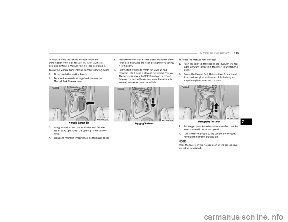
2. Remove the console storage bin to access the
Manual Park Release lever.
Console Storage Bin
3. Using a small screwdriver or similar tool, fish the tether strap up through the opening in the console
base.
4. Press and maintain firm pressure on the brake pedal. 5. Insert the screwdriver into the slot in the center of the
lever, and disengage the lever locking tab by pushing
it to the right.
6. Pull the tether strap to rotate the lever up and rearward until it locks in place in the vertical position.
The vehicle is now out of PARK and can be moved.
Release the parking brake only when the vehicle is
securely connected to a tow vehicle.
Engaging The Lever
To Reset The Manual Park Release:
1. Push the latch (at the base of the lever, on the rear side) rearward (away from the lever) to unlatch the
lever.
2. Rotate the Manual Park Release lever forward and down, to its original position, until the locking tab
snaps into place to secure the lever.
Disengaging The Lever
3. Pull up gently on the tether strap to confirm that the lever is locked in its stowed position.
4. Tuck the tether strap into the base of the console. Reinstall the console storage bin.
NOTE:When the lever is in the release position the access cover
cannot be reinstalled.
7
23_LA_OM_EN_USC_t.book Page 219
Page 222 of 300

220IN CASE OF EMERGENCY
FREEING A STUCK VEHICLE
If your vehicle becomes stuck in mud, sand, or snow, it can
often be moved using a rocking motion. Turn the steering
wheel right and left to clear the area around the front
wheels. For vehicles with automatic transmission, push
and hold the lock button on the gear selector. Then shift
back and forth between DRIVE and REVERSE
(with automatic transmission) or FIRST gear and REVERSE
(with manual transmission), while gently pressing the
accelerator. Use the least amount of accelerator pedal
pressure that will maintain the rocking motion, without
spinning the wheels or racing the engine.
NOTE:For vehicles with automatic transmission: Shifts between
DRIVE and REVERSE can only be achieved at wheel
speeds of 5 mph (8 km/h) or less. Whenever the trans -
mission remains in NEUTRAL for more than two seconds,
you must press the brake pedal to engage DRIVE or
REVERSE.
Push the ESC OFF button to place the Electronic Stability
Control (ESC) system in “Partial OFF” mode, before rocking
the vehicle
Úpage 161. Once the vehicle has been freed,
push the ESC OFF button again to restore “ESC On” mode.
CAUTION!
Racing the engine or spinning the wheels may lead to
transmission overheating and failure. Allow the engine
to idle with the transmission in NEUTRAL for at least
one minute after every five rocking-motion cycles.
This will minimize overheating and reduce the risk of
clutch or transmission failure during prolonged efforts
to free a stuck vehicle.
WARNING!
Fast spinning tires can be dangerous. Forces generated
by excessive wheel speeds may cause damage, or even
failure, of the axle and tires. A tire could explode and
injure someone. Do not spin your vehicle's wheels
faster than 30 mph (48 km/h) or for longer than
30 seconds continuously without stopping when you
are stuck and do not let anyone near a spinning wheel,
no matter what the speed.
CAUTION!
When “rocking” a stuck vehicle by shifting between
DRIVE / FIRST gear and REVERSE, do not spin the
wheels faster than 15 mph (24 km/h), or drivetrain
damage may result.
Revving the engine or spinning the wheels too fast
may lead to transmission overheating and failure.
It can also damage the tires. Do not spin the wheels
above 30 mph (48 km/h) while in gear
(no transmission shifting occurring).
23_LA_OM_EN_USC_t.book Page 220
Page 237 of 300

SERVICING AND MAINTENANCE235
(Continued)
3. Remove the used filter.
4. Install the new filter with arrows pointing in the
direction of airflow, which is toward the rear of the
vehicle (text and arrows on the filter will indicate this).
Cabin Air Filter
5. Close the filter access cover.
For the proper maintenance intervals
Úpage 223.
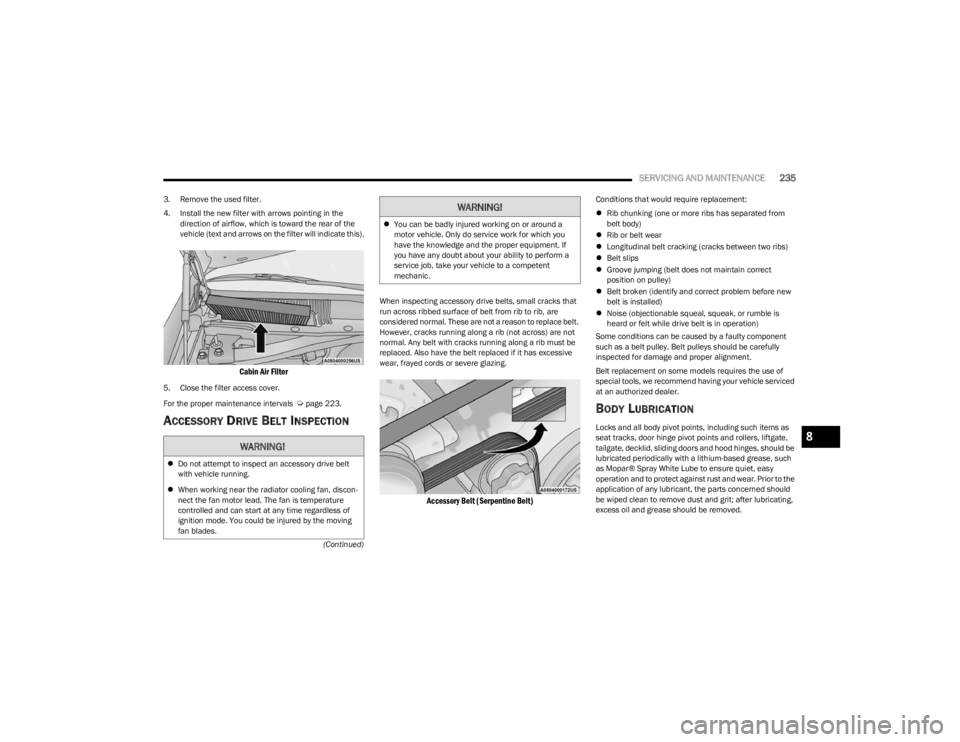
ACCESSORY DRIVE BELT INSPECTION
When inspecting accessory drive belts, small cracks that
run across ribbed surface of belt from rib to rib, are
considered normal. These are not a reason to replace belt.
However, cracks running along a rib (not across) are not
normal. Any belt with cracks running along a rib must be
replaced. Also have the belt replaced if it has excessive
wear, frayed cords or severe glazing.
Accessory Belt (Serpentine Belt)
Conditions that would require replacement:
Rib chunking (one or more ribs has separated from
belt body)
Rib or belt wear
Longitudinal belt cracking (cracks between two ribs)
Belt slips
Groove jumping (belt does not maintain correct
position on pulley)
Belt broken (identify and correct problem before new
belt is installed)
Noise (objectionable squeal, squeak, or rumble is
heard or felt while drive belt is in operation)
Some conditions can be caused by a faulty component
such as a belt pulley. Belt pulleys should be carefully
inspected for damage and proper alignment.
Belt replacement on some models requires the use of
special tools, we recommend having your vehicle serviced
at an authorized dealer.
BODY LUBRICATION
Locks and all body pivot points, including such items as
seat tracks, door hinge pivot points and rollers, liftgate,
tailgate, decklid, sliding doors and hood hinges, should be
lubricated periodically with a lithium-based grease, such
as Mopar® Spray White Lube to ensure quiet, easy
operation and to protect against rust and wear. Prior to the
application of any lubricant, the parts concerned should
be wiped clean to remove dust and grit; after lubricating,
excess oil and grease should be removed.
WARNING!
Do not attempt to inspect an accessory drive belt
with vehicle running.
When working near the radiator cooling fan, discon -
nect the fan motor lead. The fan is temperature
controlled and can start at any time regardless of
ignition mode. You could be injured by the moving
fan blades.
You can be badly injured working on or around a
motor vehicle. Only do service work for which you
have the knowledge and the proper equipment. If
you have any doubt about your ability to perform a
service job, take your vehicle to a competent
mechanic.
WARNING!
8
23_LA_OM_EN_USC_t.book Page 235
Page 238 of 300

236SERVICING AND MAINTENANCE
Particular attention should also be given to hood latching
components to ensure proper function. When performing
other underhood services, the hood latch, release
mechanism and safety catch should be cleaned and
lubricated.
The external lock cylinders should be lubricated twice a
year, preferably in the Autumn and Spring. Apply a small
amount of a high quality lubricant, such as Mopar® Lock
Cylinder Lubricant directly into the lock cylinder.
WINDSHIELD WIPER BLADES
Clean the rubber edges of the wiper blades and the
windshield periodically with a sponge or soft cloth and a
mild nonabrasive cleaner. This will remove accumulations
of salt or road film.
Operation of the wipers on dry glass for long periods may
cause deterioration of the wiper blades. Always use
washer fluid when using the wipers to remove salt or dirt
from a dry windshield.
Avoid using the wiper blades to remove frost or ice from
the windshield. Keep the blade rubber out of contact with
petroleum products such as engine oil, gasoline, etc.
NOTE:Life expectancy of wiper blades varies depending on
geographical area and frequency of use. Poor perfor -
mance of blades may be present with chattering, marks,
water lines or wet spots. If any of these conditions are
present, clean the wiper blades or replace as necessary.
Wiper Blade Removal/Installation
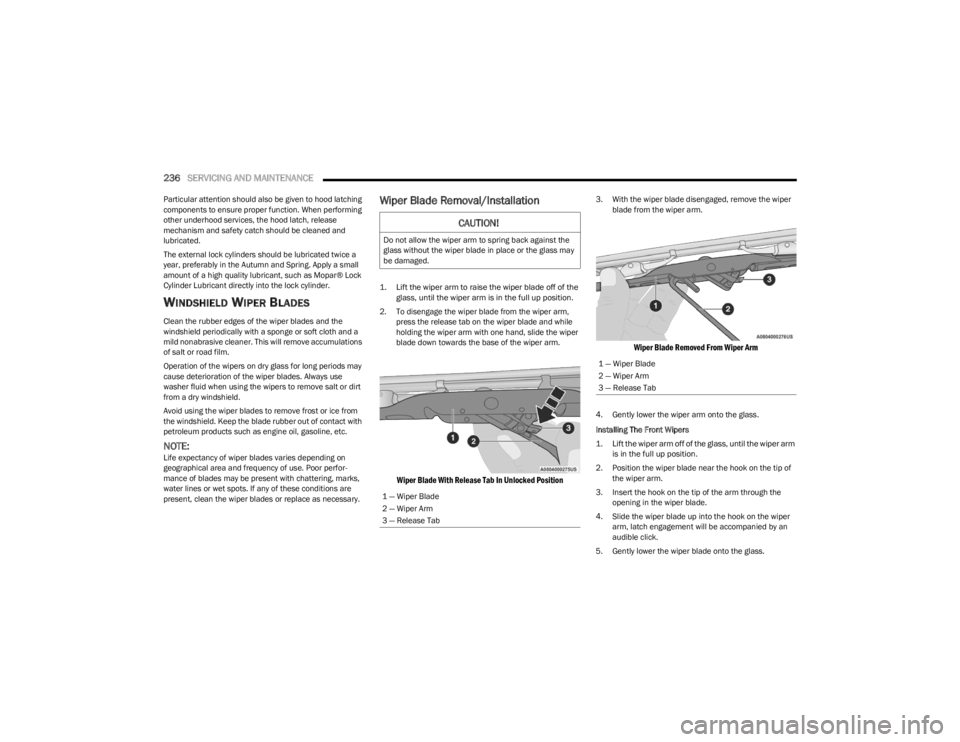
1. Lift the wiper arm to raise the wiper blade off of the glass, until the wiper arm is in the full up position.
2. To disengage the wiper blade from the wiper arm, press the release tab on the wiper blade and while
holding the wiper arm with one hand, slide the wiper
blade down towards the base of the wiper arm.
Wiper Blade With Release Tab In Unlocked Position
3. With the wiper blade disengaged, remove the wiper blade from the wiper arm.
Wiper Blade Removed From Wiper Arm
4. Gently lower the wiper arm onto the glass.
Installing The Front Wipers
1. Lift the wiper arm off of the glass, until the wiper arm is in the full up position.
2. Position the wiper blade near the hook on the tip of the wiper arm.
3. Insert the hook on the tip of the arm through the opening in the wiper blade.
4. Slide the wiper blade up into the hook on the wiper arm, latch engagement will be accompanied by an
audible click.
5. Gently lower the wiper blade onto the glass.
CAUTION!
Do not allow the wiper arm to spring back against the
glass without the wiper blade in place or the glass may
be damaged.
1 — Wiper Blade
2 — Wiper Arm
3 — Release Tab
1 — Wiper Blade
2 — Wiper Arm
3 — Release Tab
23_LA_OM_EN_USC_t.book Page 236
Page 246 of 300

244SERVICING AND MAINTENANCE
CavityCartridge Fuse Mini-Fuse Description
* If Equipped
F01 ––Spare
F02 40 Amp Green
–Radiator Fan #1 – (Non 6.2L & Non – Police)
50 Amp Red Radiator Fan (6.2L & Police)
F03 50 Amp Red –Electric Power Steering #1 *
F04 30 Amp Pink –Starter
F05 40 Amp Green –Anti-Lock Brake
F06 30 Amp Pink –Anti-Lock Brake
F07 20 Amp Blue –Police Ignition Run / ACC #1
F08 20 Amp Blue –Police Ignition Run / ACC # 2
F09 –20 Amp Yellow All-Wheel Drive Module *
F10 –10 Amp RedIntrusion MOD (300) * / Under Hood Lamp – Police
F11 –20 Amp Yellow Horns
F12 –10 Amp RedAir Conditioning Clutch
F13 ––Spare
F14 ––Spare
F15 –20 Amp Yellow Left HID Headlamp *
F16 –20 Amp Yellow Right HID Headlamp *
F18 50 Amp Red –Radiator Fan #2
F19 50 Amp Red –Electric Power Steering #2 *
F20 30 Amp Pink –Wiper Motor
F21 30 Amp Pink
–Headlamp Washers *
20 Amp Blue – Police Police Bat Feed #2
23_LA_OM_EN_USC_t.book Page 244
Page 247 of 300

SERVICING AND MAINTENANCE245
F2240 Amp Green
–LTR Cooling Pump (6.2L Eng)
20 Amp Blue – Police Police Bat Feed # 3
F23 20 Amp Blue –Police Bat Feed # 1
F24 20 Amp Blue –Police Ignition Run/ACC Feed # 3
F28 ––Spare
F29 –15 Amp Blue Auto Trans (Challenger / Police)
F30 ––Spare
F31 –25 Amp Clear Engine Module
F32 ––Spare
F33 ––Spare
F34 –25 Amp Clear ASD Feed #1
F35 –20 Amp Yellow ASD Feed #2
F36 –10 Amp RedAnti-Lock Brake Module / Steering Column Lock Module *
F37 –10 Amp RedEngine Controller
F38 –10 Amp RedAirbag Module
F39 –10 Amp RedA/C Clutch / EPS */ Vacuum Pump *
F48 –10 Amp RedAWD Module / Front Axle Disconnect *
F49 ––Spare
F50 ––Spare
F51 –20 Amp Yellow Vacuum Pump *
F52 –5 Amp TanAdaptive Cruise Control *
F53 ––Spare
Cavity Cartridge Fuse Mini-Fuse Description
* If Equipped
8
23_LA_OM_EN_USC_t.book Page 245
Page 248 of 300

246SERVICING AND MAINTENANCE
Rear Fuses
There is also a power distribution center located in the
trunk under the spare tire access panel. This center
contains fuses and relays. Fuse cavity location and
descriptions are printed on the inside of the power
distribution center cover.
Rear Power Distribution Center Location
CAUTION!
When installing the power distribution center cover, it is
important to ensure the cover is properly positioned
and fully latched. Failure to do so may allow water to get
into the power distribution center and possibly result in
an electrical system failure.
CavityCartridge Fuse Mini-FuseDescription
* If Equipped
F02 60 Amp Yellow –Front PDC Feed #1
F03 ––Spare
F04 60 Amp Yellow –Front PDC Feed #2
F05 30 Amp Pink
–Sunroof *
20 Amp Blue – Police Dome Lamp – Police
F06 40 Amp Green –Exterior Lighting #1
F07 40 Amp Green –Exterior Lighting #2
F08 30 Amp Pink –Interior Lighting
F09 40 Amp Green –Power Locks
F10 30 Amp Pink –Driver Door Control Module
F11 30 Amp Pink –Passenger Door Control Module
F12 –20 Amp YellowCigar Lighter / IP APO / RR USB
(Selectable Fuse) *
23_LA_OM_EN_USC_t.book Page 246
Page 249 of 300

SERVICING AND MAINTENANCE247
F15 40 Amp Green –HVAC Blower
F16 20 Amp Blue –Left Spot Lamp – Police
F17 20 Amp Blue –Right Spot Lamp – Police
F18 30 Amp Pink –VISM Mod (Police)
F19 ––Spare
F20 ––Spare
F21 30 Amp Pink
–Fuel Pump (Non 6.2L ADR)
40 Amp Green Fuel Pump #2 (6.2L XVC)
F22 –5 Amp TanCyber Gateway Module
F23 –10 Amp RedFuel Door SW * / Diagnostic Port
F24 –10 Amp RedIntegrated Center Stack
F25 –10 Amp RedTire Pressure Monitor System
F26 –15 Amp BlueTrans Mod (Charger / 300)
F27 –25 Amp ClearAmplifier *
F31 –25 Amp BreakerPower Seats *
F32 –15 Amp BlueHVAC Module / Cluster
F33 –15 Amp BlueIGN SW / Wireless Mod / Steer Clmn Lock
Mod / Remote Start *
F34 –10 Amp RedSteering Column Module / Clock (300)
F35 –5 Amp TanBattery Sensor
F36 –15 Amp BlueActive Exhaust Valve *
F37 –20 Amp YellowRadio
Cavity Cartridge Fuse Mini-FuseDescription
* If Equipped
8
23_LA_OM_EN_USC_t.book Page 247