2023 CHRYSLER PACIFICA wheel
[x] Cancel search: wheelPage 252 of 328
250IN CASE OF EMERGENCY
If the tire pressure is 19 psi (1.3 bar) or higher:
1. Push the Power Button to turn on Tire
Service Kit and inflate the tire to the cold
tire inflation pressure found on the tire
and loading information label located in
the driver-side door opening.
NOTE:If the tire becomes overinflated, push the Deflation Button
to reduce the tire pressure to the recommended inflation
pressure before continuing.
2. Disconnect the Tire Service Kit from the valve stem, reinstall the cap on the valve stem and unplug from
12 Volt outlet.
3. Place the Tire Service Kit in its proper storage area in the vehicle.
4. Have the tire inspected and repaired or replaced at the earliest opportunity at an authorized dealer or tire
service center.
5. Remove the Speed Limit sticker from the steering wheel after the tire has been repaired.
6. Replace the Sealant Bottle at an authorized dealer as soon as possible.
NOTE:When having the tire serviced, advise the authorized
dealer or service center that the tire has been sealed
using the Tire Service Kit.
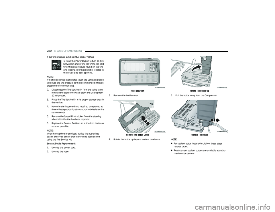
Sealant Bottle Replacement:
1. Unwrap the power cord.
2. Unwrap the hose.
Hose Location
3. Remove the bottle cover.
Remove The Bottle Cover
4. Rotate the bottle up beyond vertical to release.
Rotate The Bottle Up
5. Pull the bottle away from the Compressor.
Remove The Bottle
NOTE:
For sealant bottle installation, follow these steps
reverse order.
Replacement sealant bottles are available at autho -
rized service centers.
23_RUP_OM_EN_USC_t.book Page 250
Page 257 of 328
IN CASE OF EMERGENCY255
To Reset The Manual Park Release:
1. Apply firm pressure to the brake pedal while seated
in the driver’s seat.
2. Pull the tether strap out again, then release it.
3. Allow the tether to retract with the lever back to its original position.
4. Verify that the transmission is in PARK (P).
5. Confirm that the tether has retracted fully and reinstall the access cover. If the access cover cannot
be reinstalled, repeat steps 1 through 4.
FREEING A STUCK VEHICLE
If your vehicle becomes stuck in mud, sand or snow, it can
often be moved using a rocking motion. Turn the steering
wheel right and left to clear the area around the front
wheels. Then shift back and forth between DRIVE (D) and
REVERSE (R) while gently pressing the accelerator.
NOTE:
Shifts between DRIVE and REVERSE can only be
achieved at wheel speeds of 5 mph (8 km/h) or less.
Whenever the transmission remains in NEUTRAL (N)
for more than two seconds, you must press the brake
pedal to engage DRIVE or REVERSE. Use the least
amount of accelerator pedal pressure that will main -
tain the rocking motion without spinning the wheels or
racing the engine.
Push the ESC OFF button to place the Electronic
Stability Control (ESC) system in “Partial Off” mode,
before rocking the vehicle
Úpage 189. Once the
vehicle has been freed, push the ESC OFF button again
to restore “ESC On” mode.
WARNING!
Fast spinning tires can be dangerous. Forces generated
by excessive wheel speeds may cause damage, or even
failure, of the axle and tires. A tire could explode and
injure someone. Do not spin your vehicle's wheels
faster than 30 mph (48 km/h) or for longer than 30
seconds continuously without stopping when you are
stuck and do not let anyone near a spinning wheel, no
matter what the speed.
CAUTION!
Racing the engine or spinning the wheels may lead to
transmission overheating and failure. Allow the
engine to idle with the transmission in NEUTRAL for
at least one minute after every five rocking-motion
cycles. This will minimize overheating and reduce the
risk of transmission failure during prolonged efforts
to free a stuck vehicle.
When “rocking” a stuck vehicle by shifting between
DRIVE and REVERSE, do not spin the wheels faster
than 15 mph (24 km/h), or drivetrain damage may
result.
Revving the engine or spinning the wheels too fast
may lead to transmission overheating and failure. It
can also damage the tires. Do not spin the wheels
above 30 mph (48 km/h) while in gear (no transmis -
sion shifting occurring).
7
23_RUP_OM_EN_USC_t.book Page 255
Page 258 of 328
256IN CASE OF EMERGENCY
TOWING A DISABLED VEHICLE
This section describes procedures for towing a disabled vehicle using a commercial towing service.
Proper towing or lifting equipment is required to prevent damage to your vehicle. Use only tow bars and other equipment designed for this purpose, following equipment manufacturer’s
instructions. Use of safety chains is mandatory. Attach a tow bar or other towing device to main structural members of the vehicle, not to fascia/bumper or associated brackets. State
and local laws regarding vehicles under tow must be observed.
NOTE:
You must ensure that the Auto Park Brake feature is disabled before towing this vehicle (if rear wheels are on the ground), to avoid inadvertent Electric Park Brake (EPB) engagement.
The Auto Park Brake feature is enabled or disabled via the customer programmable features in the Uconnect Settings.
Vehicles with a discharged battery or total electrical failure when the EPB is engaged, will need a wheel dolly or jack to raise the rear wheels off the ground when moving the vehicle
onto a flatbed. Towing Condition
Wheels OFF The Ground FWD MODELS AWD MODELS
Flat Tow NONENOT ALLOWED NOT ALLOWED
Wheel Lift Or Dolly Tow Front
ACCEPTABLE METHOD NOT ALLOWED
Rear NOT ALLOWED NOT ALLOWED
Flatbed ALLBEST METHOD BEST METHOD
23_RUP_OM_EN_USC_t.book Page 256
Page 259 of 328
IN CASE OF EMERGENCY257
(Continued)
FCA US LLC recommends towing your vehicle with all four
wheels
OFF the ground using a flatbed.
If flatbed equipment is not available, this vehicle must be
towed with the front wheels OFF the ground (using a
towing dolly, or wheel lift equipment with the front wheels
raised).
NOTE:Ensure that the Electric Park Brake is released, and
remains released, while being towed.
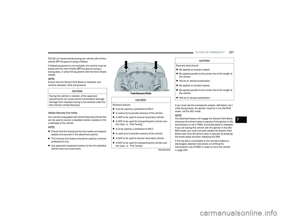
Vehicle Recovery Tow Points
Your vehicle is equipped with Vehicle Recovery Points that
can be used to recover a disabled vehicle, located on the
underbody of the vehicle.
NOTE:
Ensure that the towing service tow hooks are properly
seated and secured in the attachment points.
This recovery tow feature should be used by a trained
professional only.
Use approved receptacle location to free the disabled
vehicle from its environment.
Front Recovery Points
If you must use the accessories (wipers, defrosters, etc.)
while being towed, the ignition must be in the ON/RUN
mode, not the ACC mode.
NOTE:The Safehold feature will engage the Electric Park Brake
whenever the driver's door is opened (if the ignition is ON,
transmission is not in PARK, and brake pedal is released).
If you are towing this vehicle with the ignition in the ON/
RUN mode, you must manually disable the Electric Park
Brake each time the driver's door is opened, by pressing
the brake pedal and then releasing the EPB.
If the key fob is unavailable or the vehicle's battery is
discharged, detailed instructions on shifting the
transmission out of PARK in order to move the vehicle
Úpage 254.
CAUTION!
Towing this vehicle in violation of the approved
requirements can cause severe transmission damage.
Damage from improper towing is not covered under the
New Vehicle Limited Warranty.
CAUTION!
Recovery feature:
Is to be used by a professional ONLY.
Is used only to provide recovery of the vehicle.
Is NOT to be used to recover secondary vehicle.
Is NOT to be used for transporting the vehicle over
the road, i.e. “Flat Towing”.
Is to be used by a professional ONLY.
Is used only to provide recovery of the vehicle.
Is NOT to be used to recover secondary vehicle.
Is NOT to be used for transporting the vehicle over
the road, i.e. “Flat Towing”.
Recovery load should:
Be applied at constant speed.
Be applied parallel to the center line of the length of
the vehicle.
Not be an abrupt acceleration.
Be applied at constant speed.
Be applied parallel to the center line of the length of
the vehicle.
Not be an abrupt acceleration.
CAUTION!
7
23_RUP_OM_EN_USC_t.book Page 257
Page 260 of 328
258IN CASE OF EMERGENCY
ALL WHEEL DRIVE (AWD) MODELS
FCA US LLC recommends towing your vehicle with all four
wheels OFF the ground using a flatbed.
ENHANCED ACCIDENT RESPONSE SYSTEM
(EARS)
This vehicle is equipped with an Enhanced Accident
Response System.
This feature is a communication network that takes effect
in the event of an impact. Detailed information can be
found on
Úpage 218.
EVENT DATA RECORDER (EDR)
This vehicle is equipped with an event data recorder
(EDR). The main purpose of an EDR is to record data that
will assist in understanding how a vehicle’s systems
performed under certain crash or near crash-like
situations, such as an air bag deployment or hitting a road
obstacle. Detailed information can be found on
Úpage 219.
CAUTION!
Do not use sling-type equipment when towing.
Vehicle damage may occur.
When securing the vehicle to a flatbed truck, do not
attach to front or rear suspension components.
Damage to your vehicle may result from improper
towing.
Ensure that the Electric Park Brake is released, and
remains released, while being towed.
CAUTION!
Towing this vehicle using any other method can
cause severe transmission and/or transfer case
damage.
Damage from improper towing is not covered under
the New Vehicle Limited Warranty.
23_RUP_OM_EN_USC_t.book Page 258
Page 283 of 328

SERVICING AND MAINTENANCE281
30 Amp mini fuse is substituted for 25 Amp Circuit Breaker.F91
–15 Amp BlueFront Ventilated Seats/Heated Steering
Wheel *
F92 –5 Amp Tan Security Gateway
F93 ––Not Populated
F94 40 Amp Green –ESC Motor Pump
F95A –10 Amp RedUSB Charge Port — ACC/RUN
F95B –10 Amp Red
Selectable Fuse Location – USB IP (Direct) B+
F96 –10 Amp Red Airbag
F97 –10 Amp Red Airbag
F98 –15 Amp Blue Left HID Headlamp *
F99 30 Amp Pink –Trailer Tow Elect Brake Module *
F100 –10 Amp RedHeadlamp Level / RR Camera / Blindspot /
Humidity SNSR / In Car Temp SNSR / Headlamp SW *
Circuit Breakers
CB1 25 AmpPower Seats (Driver)
CB2 25 Amp *Power Seats (Pass)
CB3 25 AmpFRT PWR Window W/O Door Nodes + RR
PWR Window Lockout
Cavity
Cartridge Fuse Blade FuseDescription
*If Equipped
8
23_RUP_OM_EN_USC_t.book Page 281
Page 284 of 328
282SERVICING AND MAINTENANCE
BULB REPLACEMENT
Replacement Bulbs, Names, And Part
Numbers
In the instance a bulb needs to be replaced, this section
includes bulb description and replacement part numbers.
NOTE:Your vehicle is equipped with LED lamps. For replacement
of LED lamps, see an authorized dealer.
Interior Bulbs — Halogen
NOTE:Your vehicle is equipped with LED lamps. For replacement
of LED lamps, see an authorized dealer.
Exterior Bulbs — Halogen
Replacing Exterior Bulbs
FRONT TURN SIGNAL LAMP
See the following steps to replace:
1. Open the hood.
2. Twist the front turn signal lamp socket assembly
counterclockwise, and then remove the front turn
signal lamp assembly from the lamp housing.
Front Turn Signal Lamp Socket
3. Pull the bulb out of the socket and insert the replacement bulb.
4. Install the front turn signal lamp socket assembly into the housing, and rotate the front turn signal lamp
socket clockwise to lock it in place.
FRONT AND REAR SIDE MARKER LAMPS
See the following steps to replace:
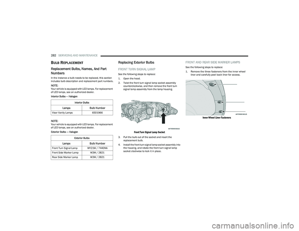
1. Remove the three fasteners from the inner wheel liner and carefully peel back liner for access.
Inner Wheel Liner Fasteners
Interior Bulbs
Lamps Bulb Number
Visor Vanity Lamps 6501966
Exterior Bulbs
Lamps Bulb Number
Front Turn Signal Lamp WY21W / 7440NA
Front Side Marker Lamp W3W / 2821
Rear Side Marker Lamp W3W / 2821
23_RUP_OM_EN_USC_t.book Page 282
Page 285 of 328

SERVICING AND MAINTENANCE283
2. Firmly grab the front side marker lamp socket and
rotate a quarter turn counterclockwise to remove it
from the lamp assembly.
Front Side Marker Lamp Bulb Removal
3. Remove bulb from the front side marker lamp socket and replace with a new bulb.
4. Install front side marker lamp socket in lamp assembly and rotate a quarter turn clockwise to lock
into place.
5. Position the inner wheel liner in place and install the three fasteners.
TIRES
TIRE SAFETY INFORMATION
Tire safety information will cover aspects of the following
information: Tire Markings, Tire Identification Numbers,
Tire Terminology and Definitions, Tire Pressures, and Tire
Loading.
Tire Markings
Tire Markings
NOTE:
P (Passenger) — Metric tire sizing is based on US design
standards. P-Metric tires have the letter “P” molded
into the sidewall preceding the size designation.
Example: P215/65R15 95H.
European — Metric tire sizing is based on European
design standards. Tires designed to this standard have
the tire size molded into the sidewall beginning with the
section width. The letter "P" is absent from this tire size
designation. Example: 215/65R15 96H.
LT (Light Truck) — Metric tire sizing is based on US
design standards. The size designation for LT-Metric
tires is the same as for P-Metric tires except for the
letters “LT” that are molded into the sidewall preceding
the size designation. Example: LT235/85R16.
Temporary spare tires are designed for temporary
emergency use only. Temporary high pressure compact
spare tires have the letter “T” or “S” molded into the
sidewall preceding the size designation. Example:
T145/80D18 103M.
High flotation tire sizing is based on US design stan -
dards and it begins with the tire diameter molded into
the sidewall. Example: 31x10.5 R15 LT.
1 — US DOT Safety Standards Code
(TIN)
2 — Size Designation
3 — Service Description
4 — Maximum Load
5 — Maximum Pressure
6 — Treadwear, Traction and
Temperature Grades
8
23_RUP_OM_EN_USC_t.book Page 283