2023 CHEVROLET SILVERADO 1500 stop start
[x] Cancel search: stop startPage 321 of 463

Chevrolet Silverado 1500 Owner Manual (GMNA-Localizing-U.S./Canada/
Mexico/Paraguay-16515119) - 2023 - CRC - 6/2/22
320 Driving and Operating
see a tire or trailer dealer for service. The
learning process must be repeated when the
trailer tires are rotated or replaced.
Tool Method: A TTPMS activation tool can
be purchased separately to learn the sensor
locations.
Manual Method: Without the tool, the air
pressure can be increased or decreased in
each tire for 10 seconds. Do not exceed the
maximum inflation pressure found on the
tire sidewalls. Make sure to readjust tire
pressure to the recommended level when
the process is complete.
Sensor Learning Steps
To complete the sensor-to-vehicle learn
process:1. Touch Start on the Learn Sensors screen. The horn chirps twice and the Learning
Active screen appears on the
infotainment screen.
2. Start with the driver side front trailer tire.
3. Activate the tool near the valve stem or adjust the air pressure of this tire until
the horn chirps and all working vehicle
and trailer lights flash. The process stops without saving the
sensor locations if this step takes more
than two minutes.
4. Move to the next tire and repeat Step 3 for each sensor. The horn chirps twice
when all sensors are completed.
5. Return to the vehicle to complete the setup.
Maintenance Reminders
To set up maintenance reminders, touch the
Trailer Maintenance icon. Follow the
onscreen prompts. The maximum number of
reminders is 50.
Towing Assist
To set up towing assist features,
if equipped, touch the towing assist icon.
1. Select the number of axles on the trailer.
2. Enter trailer dimensions as prompted.
Follow the onscreen instructions to complete
setup for available features.
Certain trailer features require a compatible
trailer profile be configured and selected.
A compatible trailer is a box type trailer
(cargo, camper, etc.) with a conventional
hitch.
Transparent Trailer Setup
If equipped, a rear trailer camera must be
mounted on the trailer and electrically
connected to the vehicle before transparent
trailer feature can be used. See Assistance
Systems for Parking or Backing 0274.
Trailer dimensions must be in range and
transparent trailer must be calibrated prior
to use: 1. If trailer dimensions are out of range, this feature will be unavailable.
2. Ensure rear trailer camera is connected.
3. Follow instructions to drive forward to complete calibration.
.Trailer Length: 300 cm (118.1 in) –970 cm
(381.8 in). Measure from center of coupler
to furthest rear point on the trailer.
.Trailer Width: 120 cm (47.2 in) –260 cm
(102.3 in). Measure from left edge of
trailer to right edge.
.Trailer Height: 1 cm (0.39 in) –450 cm
(177.1 in). Measure from ground to tallest
point of the trailer.
.Hitching Point Length: 180 cm (70.8 in) –
970 cm (381.8 in). Measure from center of
coupler to middle of tires.
Page 323 of 463
Chevrolet Silverado 1500 Owner Manual (GMNA-Localizing-U.S./Canada/
Mexico/Paraguay-16515119) - 2023 - CRC - 6/2/22
322 Driving and Operating
Lights
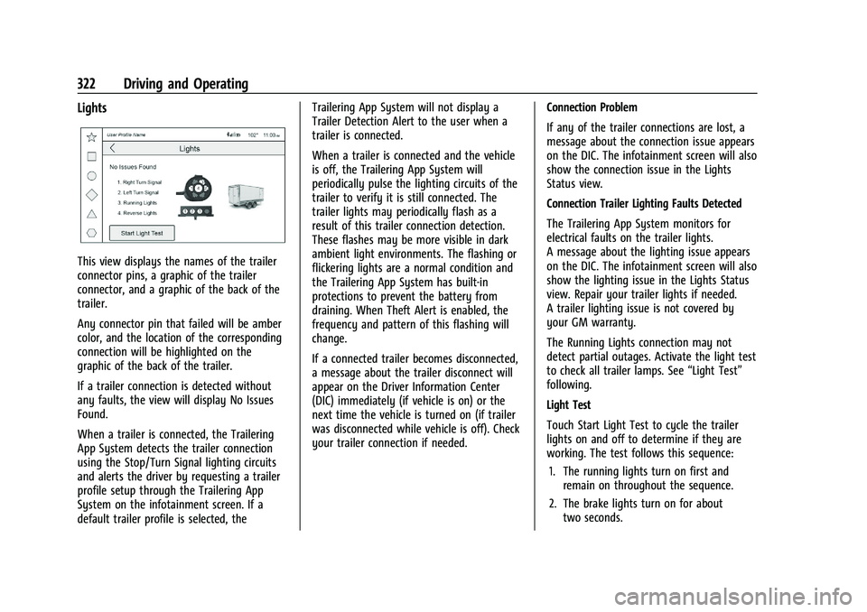
This view displays the names of the trailer
connector pins, a graphic of the trailer
connector, and a graphic of the back of the
trailer.
Any connector pin that failed will be amber
color, and the location of the corresponding
connection will be highlighted on the
graphic of the back of the trailer.
If a trailer connection is detected without
any faults, the view will display No Issues
Found.
When a trailer is connected, the Trailering
App System detects the trailer connection
using the Stop/Turn Signal lighting circuits
and alerts the driver by requesting a trailer
profile setup through the Trailering App
System on the infotainment screen. If a
default trailer profile is selected, theTrailering App System will not display a
Trailer Detection Alert to the user when a
trailer is connected.
When a trailer is connected and the vehicle
is off, the Trailering App System will
periodically pulse the lighting circuits of the
trailer to verify it is still connected. The
trailer lights may periodically flash as a
result of this trailer connection detection.
These flashes may be more visible in dark
ambient light environments. The flashing or
flickering lights are a normal condition and
the Trailering App System has built-in
protections to prevent the battery from
draining. When Theft Alert is enabled, the
frequency and pattern of this flashing will
change.
If a connected trailer becomes disconnected,
a message about the trailer disconnect will
appear on the Driver Information Center
(DIC) immediately (if vehicle is on) or the
next time the vehicle is turned on (if trailer
was disconnected while vehicle is off). Check
your trailer connection if needed.
Connection Problem
If any of the trailer connections are lost, a
message about the connection issue appears
on the DIC. The infotainment screen will also
show the connection issue in the Lights
Status view.
Connection Trailer Lighting Faults Detected
The Trailering App System monitors for
electrical faults on the trailer lights.
A message about the lighting issue appears
on the DIC. The infotainment screen will also
show the lighting issue in the Lights Status
view. Repair your trailer lights if needed.
A trailer lighting issue is not covered by
your GM warranty.
The Running Lights connection may not
detect partial outages. Activate the light test
to check all trailer lamps. See
“Light Test”
following.
Light Test
Touch Start Light Test to cycle the trailer
lights on and off to determine if they are
working. The test follows this sequence:
1. The running lights turn on first and remain on throughout the sequence.
2. The brake lights turn on for about two seconds.
Page 332 of 463
Chevrolet Silverado 1500 Owner Manual (GMNA-Localizing-U.S./Canada/
Mexico/Paraguay-16515119) - 2023 - CRC - 6/2/22
Vehicle Care 331
Vehicle Care
General Information
General Information . . . . . . . . . . . . . . . . . . . 332
California Perchlorate MaterialsRequirements . . . . . . . . . . . . . . . . . . . . . . . . 332
Accessories and Modifications . . . . . . . . . 332
Vehicle Checks
Doing Your Own Service Work . . . . . . . . . 333
Hood . . . . . . . . . . . . . . . . . . . . . . . . . . . . . . . . . . 333
Engine Compartment Overview . . . . . . . . 335
Engine Oil . . . . . . . . . . . . . . . . . . . . . . . . . . . . . 338
Engine Oil Life System . . . . . . . . . . . . . . . . 340
Automatic Transmission Fluid . . . . . . . . . 340
Engine Air Filter Life System . . . . . . . . . . . 341
Engine Air Cleaner/Filter . . . . . . . . . . . . . . . 341
Cooling System . . . . . . . . . . . . . . . . . . . . . . . . 343
Engine Overheating . . . . . . . . . . . . . . . . . . . 346
Overheated Engine Protection Operating Mode . . . . . . . . . . . . . . . . . . . . . 347
Engine Fan . . . . . . . . . . . . . . . . . . . . . . . . . . . . 348
Washer Fluid . . . . . . . . . . . . . . . . . . . . . . . . . . 348
Brakes . . . . . . . . . . . . . . . . . . . . . . . . . . . . . . . . 349
Brake Pad Life System . . . . . . . . . . . . . . . . 349
Brake Fluid . . . . . . . . . . . . . . . . . . . . . . . . . . . . 350
Battery - North America . . . . . . . . . . . . . . . 351
Four-Wheel Drive . . . . . . . . . . . . . . . . . . . . . . 353
Front Axle . . . . . . . . . . . . . . . . . . . . . . . . . . . . . 354
Rear Axle . . . . . . . . . . . . . . . . . . . . . . . . . . . . . . 354 Automatic Transmission Shift Lock
Control Function Check (Mechanical
Shifter) . . . . . . . . . . . . . . . . . . . . . . . . . . . . . . 354
Park Brake and P (Park) Mechanism Check . . . . . . . . . . . . . . . . . . . . . . . . . . . . . . . . 354
Wiper Blade Replacement . . . . . . . . . . . . . 355
Glass Replacement . . . . . . . . . . . . . . . . . . . . . 355
Windshield Replacement . . . . . . . . . . . . . . . 355
Gas Strut(s) . . . . . . . . . . . . . . . . . . . . . . . . . . . 356Headlamp Aiming
Front Headlamp Aiming . . . . . . . . . . . . . . . 356
Bulb Replacement
Bulb Replacement . . . . . . . . . . . . . . . . . . . . . 357
Halogen Bulbs . . . . . . . . . . . . . . . . . . . . . . . . . 357
LED Lighting . . . . . . . . . . . . . . . . . . . . . . . . . . . 357
Headlamps, Front Turn Signal, Sidemarker, and Parking Lamps . . . . . . 357
Taillamps, Turn Signal, Stoplamps, and Back-Up Lamps . . . . . . . . . . . . . . . . . . . . . . 358
Center High-Mounted Stoplamp (CHMSL) and Cargo Lamp . . . . . . . . . . . . 359
License Plate Lamp . . . . . . . . . . . . . . . . . . . . 359
Electrical System
Electrical System Overload . . . . . . . . . . . . 360
Fuses and Circuit Breakers . . . . . . . . . . . . . 361
Engine Compartment Fuse Block . . . . . . 362
Instrument Panel Fuse Block (Left) . . . . 365
Instrument Panel Fuse Block (Right) . . . 367
Wheels and Tires
Tires . . . . . . . . . . . . . . . . . . . . . . . . . . . . . . . . . . 369
All-Season Tires . . . . . . . . . . . . . . . . . . . . . . . 370
Winter Tires . . . . . . . . . . . . . . . . . . . . . . . . . . . 370
All-Terrain Tires . . . . . . . . . . . . . . . . . . . . . . . 370
Tire Sidewall Labeling . . . . . . . . . . . . . . . . . . 371
Tire Designations . . . . . . . . . . . . . . . . . . . . . . 372
Tire Terminology and Definitions . . . . . . 374
Tire Pressure . . . . . . . . . . . . . . . . . . . . . . . . . . 375
Tire Pressure Monitor System . . . . . . . . . 377
Tire Pressure Monitor Operation . . . . . . . 377
Tire Inspection . . . . . . . . . . . . . . . . . . . . . . . . . 381
Tire Rotation . . . . . . . . . . . . . . . . . . . . . . . . . . 382
When It Is Time for New Tires . . . . . . . . 383
Buying New Tires . . . . . . . . . . . . . . . . . . . . . 383
Different Size Tires and Wheels . . . . . . . 385
Uniform Tire Quality Grading . . . . . . . . . 385
Wheel Alignment and Tire Balance . . . . 386
Wheel Replacement . . . . . . . . . . . . . . . . . . . 386
Tire Chains . . . . . . . . . . . . . . . . . . . . . . . . . . . . 387
If a Tire Goes Flat . . . . . . . . . . . . . . . . . . . . . 387
Tire Changing . . . . . . . . . . . . . . . . . . . . . . . . . 389
Full-Size Spare Tire . . . . . . . . . . . . . . . . . . . . 399
Jump Starting
Jump Starting - North America . . . . . . . . 399
Towing the Vehicle
Transporting a Disabled Vehicle . . . . . . . 402
Recreational Vehicle Towing . . . . . . . . . . . 403
Page 334 of 463
Chevrolet Silverado 1500 Owner Manual (GMNA-Localizing-U.S./Canada/
Mexico/Paraguay-16515119) - 2023 - CRC - 6/2/22
Vehicle Care 333
GM Accessories are designed to complement
and function with other systems on the
vehicle. See your dealer to accessorize the
vehicle using genuine GM Accessories
installed by a dealer technician.
Also, seeAdding Equipment to the
Airbag-Equipped Vehicle 068.
Vehicle Checks
Doing Your Own Service Work
{Warning
It can be dangerous to work on your
vehicle if you do not have the proper
knowledge, service manual, tools,
or parts. Always follow owner’s manual
procedures and consult the service
manual for your vehicle before doing any
service work.
If doing some of your own service work, use
the proper service manual. It tells you much
more about how to service the vehicle than
this manual can. To order the proper service
manual, see Publication Ordering
Information 0437. This vehicle has an airbag system. Before
attempting to do your own service work,
see
Servicing the Airbag-Equipped Vehicle
0 68.
If equipped with remote vehicle start, open
the hood before performing any service
work to prevent remote starting the vehicle
accidentally. See Remote Vehicle Start 018.
Keep a record with all parts receipts and list
the mileage and the date of any service
work performed. See Maintenance Records
0 424.Caution
Even small amounts of contamination can
cause damage to vehicle systems. Do not
allow contaminants to contact the fluids,
reservoir caps, or dipsticks.
Hood
{Warning
For vehicles with auto engine stop/start,
turn the vehicle off before opening the
hood. If the vehicle is on, the engine will
start when the hood is opened. You or
others could be injured.
{Warning
Components under the hood can get hot
from running the engine. To help avoid
the risk of burning unprotected skin,
never touch these components until they
have cooled, and always use a glove or
towel to avoid direct skin contact.
Clear any snow from the hood before
opening.
To open the hood: 1. Pull the hood release lever with the
isymbol. It is on the lower left side
of the instrument panel.
Page 347 of 463
Chevrolet Silverado 1500 Owner Manual (GMNA-Localizing-U.S./Canada/
Mexico/Paraguay-16515119) - 2023 - CRC - 6/2/22
346 Vehicle Care
1. Remove the coolant surge tank pressurecap when the cooling system, including
the coolant surge tank pressure cap and
upper radiator hose, is no longer hot.
Turn the pressure cap slowly
counterclockwise about one full turn. If a
hiss is heard, wait for that to stop.
A hiss means there is still some
pressure left.
2. Keep turning the pressure cap slowly, and remove it.
3. Fill the coolant surge tank with the proper mixture to the full cold mark.
4. With the coolant surge tank pressure cap off, start the engine and let it run until
the engine coolant temperature gauge
indicates approximately 90 °C (195 °F).
By this time, the coolant level inside the
coolant surge tank may be lower. If the
level is lower, add more of the proper
mixture to the coolant surge tank until
the level reaches the indicated mark.
5. Replace the pressure cap tightly.
6. Verify coolant level after the engine is shut off and the coolant is cold.
If necessary, repeat coolant fill procedure
Steps 1–6.Caution
If the pressure cap is not tightly installed,
coolant loss and engine damage may
occur. Be sure the cap is properly and
tightly secured.
Engine Overheating
If the vehicle has the Duramax diesel
engine, see the Duramax diesel supplement.
Caution
Do not run the engine if there is a leak
in the engine cooling system. This can
cause a loss of all coolant and can
damage the system and vehicle. Have
any leaks fixed right away.
The vehicle has several indicators to warn of
engine overheating.
There is a coolant temperature gauge in the
vehicle's instrument cluster. See Engine
Coolant Temperature Gauge 0112.
In addition, there are ENGINE OVERHEATED
STOP ENGINE, ENGINE OVERHEATED IDLE
ENGINE, and ENGINE POWER IS REDUCED
messages in the Driver Information
Center (DIC). If the decision is made not to lift the hood
when this warning appears, get service help
right away. See
Roadside Assistance Program
0 433.
If the decision is made to lift the hood,
make sure the vehicle is parked on a level
surface.
2.7L L4, 5.3L V8, and 6.2L V8 Engines
Check to see if the engine cooling fans are
running. If the engine is overheating, the
fans should be running. If they are not, do
not continue to run the engine and have the
vehicle serviced.
If the engine or transmission detects an
impending hot fluid condition, then the
transmission may force upshifts to limit
temperatures. Downshifts may also be
prevented in this instance. Normal operation
may continue unless the display indicates
there is a hot condition and engine should
be idled.
Page 352 of 463
Chevrolet Silverado 1500 Owner Manual (GMNA-Localizing-U.S./Canada/
Mexico/Paraguay-16515119) - 2023 - CRC - 6/2/22
Vehicle Care 351
Always clean the brake fluid reservoir cap
and the area around the cap before
removing it.
Do not top off the brake fluid. Adding fluid
does not correct a leak. If fluid is added
when the linings are worn, there will be too
much fluid when new brake linings are
installed. Add or remove fluid, as necessary,
only when work is done on the brake
hydraulic system.
{Warning
If too much brake fluid is added, it can
spill on the engine and burn, if the
engine is hot enough. You or others could
be burned, and the vehicle could be
damaged. Add brake fluid only when
work is done on the brake hydraulic
system.
When the brake fluid falls to a low level,
the brake warning light comes on. See Brake
System Warning Light 0118.
Brake fluid absorbs water over time which
degrades the effectiveness of the brake fluid.
Replace brake fluid at the specified intervals
to prevent increased stopping distance. See
Maintenance Schedule 0417. What to Add
Use only GM approved DOT 4 brake fluid
from a clean, sealed container. See
Recommended Fluids and Lubricants
0421.
{Warning
The wrong or contaminated brake fluid
could result in damage to the brake
system. This could result in the loss of
braking leading to a possible injury.
Always use the proper GM approved
brake fluid.
Caution
If brake fluid is spilled on the vehicle's
painted surfaces, the paint finish can be
damaged. Immediately wash off any
painted surface.
Battery - North America
The original equipment battery is
maintenance free. Do not remove the cap
and do not add fluid.
Refer to the replacement number shown on
the original battery label when a new
battery is needed. See Engine Compartment
Overview 0335 for battery location. Stop/Start System
Vehicles equipped with a 2.7L L3B, , 5.3L L84
or 6.2L L87 are equipped with a Stop/Start
system to shut off the engine to help
conserve fuel. See
Stop/Start System 0213.
Vehicles with the Stop/Start system have an
Absorbed Glass Mat (AGM) 12-volt battery.
Installation of a standard 12-volt battery will
result in reduced 12-volt battery life. When
using a 12-volt battery charger on the 12-volt
AGM battery, some chargers have an AGM
battery setting on the charger. If available,
use the AGM setting on the charger to limit
charge voltage to 14.8 volts. Follow the
charger manufacturer’s instructions.
{Warning
WARNING: Battery posts, terminals and
related accessories can expose you to
chemicals including lead and lead
compounds, which are known to the
State of California to cause cancer and
birth defects or other reproductive harm.
Wash hands after handling. For more
information go to
www.P65Warnings.ca.gov.
See California Proposition 65 Warning 01.
Page 353 of 463
Chevrolet Silverado 1500 Owner Manual (GMNA-Localizing-U.S./Canada/
Mexico/Paraguay-16515119) - 2023 - CRC - 6/2/22
352 Vehicle Care
Vehicle Storage
{Warning
Batteries have acid that can burn you and
gas that can explode. You can be badly
hurt if you are not careful. Always wear
eye protection. SeeJump Starting - North
America 0399 for tips on working
around a battery without getting hurt.
Infrequent Usage: Remove the black,
negative (−) cable from the battery to keep
the battery from running down.
Extended Storage: Remove the black,
negative (−) cable from the battery or use a
battery trickle charger.
Negative Battery Cable Disconnection
{Warning
Before disconnecting the negative battery
cable, turn off all features, turn the
ignition off, and remove the key,
if equipped, from the vehicle. If this is
not done, you or others could be injured,
and the vehicle could be damaged.
Caution
If the battery is disconnected with the
ignition on or the vehicle in Retained
Accessory Power (RAP), the OnStar
back-up battery will be permanently
discharged and will need to be replaced.
1. Make sure the lamps, features, and accessories are turned off.
2. Turn the ignition off and remove the key, if equipped.
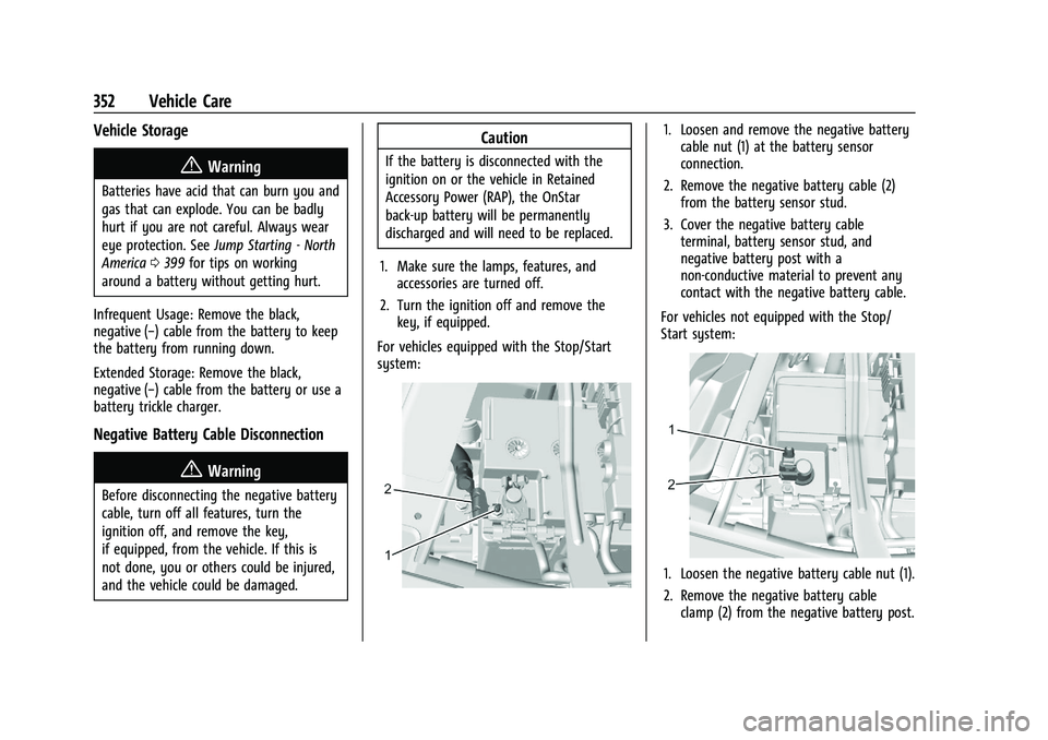
For vehicles equipped with the Stop/Start
system:
1. Loosen and remove the negative battery cable nut (1) at the battery sensor
connection.
2. Remove the negative battery cable (2) from the battery sensor stud.
3. Cover the negative battery cable terminal, battery sensor stud, and
negative battery post with a
non-conductive material to prevent any
contact with the negative battery cable.
For vehicles not equipped with the Stop/
Start system:
1. Loosen the negative battery cable nut (1).
2. Remove the negative battery cable clamp (2) from the negative battery post.
Page 354 of 463
Chevrolet Silverado 1500 Owner Manual (GMNA-Localizing-U.S./Canada/
Mexico/Paraguay-16515119) - 2023 - CRC - 6/2/22
Vehicle Care 353
3. Cover the negative battery cable clamp,and negative battery post with a
non-conductive material to prevent any
contact with the negative battery cable.
Negative Battery Cable Reconnection
Caution
When reconnecting the battery:
.Use the original nut from the vehicle
to secure the negative battery cable.
Do not use a different nut. If you
need a replacement nut, see your
dealer.
.Tighten the nut with a hand tool. Do
not use an impact wrench or power
tools to tighten the nut.
The vehicle could be damaged if these
guidelines are not followed.
Caution
Do not use paints, lubricants, or corrosion
inhibitors on the nut that secures the
negative battery cable to the vehicle. This
could damage the vehicle. For vehicles equipped with the Stop/Start
system:
1. Install the negative battery cable to the battery sensor stud.
2. Install the negative battery cable nut to the battery sensor stud and tighten.
3. Turn the ignition on.
For vehicles not equipped with the Stop/
Start system: 1. Install the negative battery cable clamp to the negative battery post.
2. Tighten the negative battery cable nut.
3. Turn the ignition on.
Four-Wheel Drive
Transfer Case
When to Check Lubricant
Refer to Maintenance Schedule 0417 to
determine when to check the lubricant.
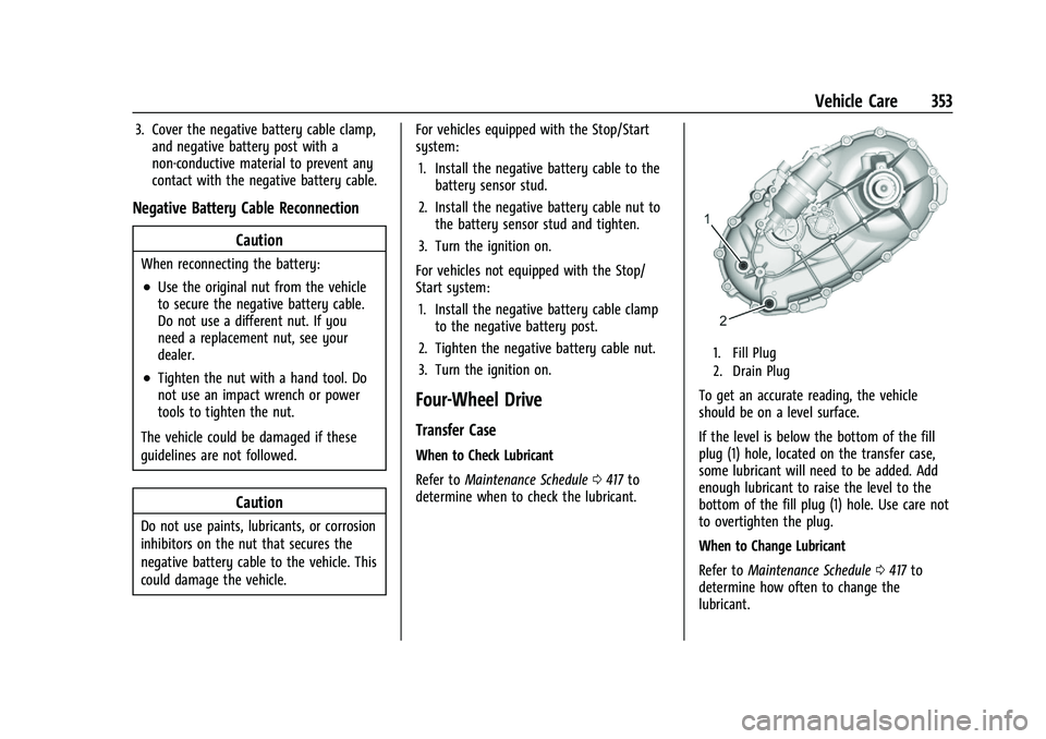
1. Fill Plug
2. Drain Plug
To get an accurate reading, the vehicle
should be on a level surface.
If the level is below the bottom of the fill
plug (1) hole, located on the transfer case,
some lubricant will need to be added. Add
enough lubricant to raise the level to the
bottom of the fill plug (1) hole. Use care not
to overtighten the plug.
When to Change Lubricant
Refer to Maintenance Schedule 0417 to
determine how often to change the
lubricant.