2023 CHEVROLET CORVETTE oil temperature
[x] Cancel search: oil temperaturePage 4 of 351

Chevrolet Corvette Owner Manual (GMNA-Localizing-U.S./Canada/Mexico-
16287457) - 2023 - CRC - 3/10/22
Introduction 3
A circle with a slash through it is a safety
symbol which means“Do not,” “Do not do
this,” or“Do not let this happen.”
Symbols
The vehicle has components and labels that
use symbols instead of text. Symbols are
shown along with the text describing the
operation or information relating to a
specific component, control, message, gauge,
or indicator.
M:Shown when the owner’s manual has
additional instructions or information.
*: Shown when the service manual has
additional instructions or information.
0: Shown when there is more information
on another page — “see page.” Vehicle Symbol Chart
Here are some additional symbols that may
be found on the vehicle and what they
mean. See the features in this manual for
information.
u:
Air Conditioning System
G:Air Conditioning Refrigerant Oil
9:Airbag Readiness Light
!:Antilock Brake System (ABS)
$:Brake System Warning Light
z: Carbon Monoxide
9:Dispose of Used Components Properly
P:Do Not Apply High Pressure Water
B:Engine Coolant Temperature
_:Flame/Fire Prohibited
H: Flammable
R:Fuse Block Cover Lock Location
+:Fuses
j:ISOFIX/LATCH System Child Restraints
Q:Keep Fuse Block Covers Properly
Installed
A: Lane Keep Assist
*: Malfunction Indicator Lamp
::Oil Pressure
X:Park Assist
O:Power
7:Rear Cross Traffic Alert
I:Registered Technician
/:Remote Vehicle Start
h:Risk of Electrical Fire
>:Seat Belt Reminders
I:Side Blind Zone Alert
7:Tire Pressure Monitor
d:Traction Control/StabiliTrak/Electronic
Stability Control (ESC)
a: Under Pressure
Page 14 of 351
Chevrolet Corvette Owner Manual (GMNA-Localizing-U.S./Canada/Mexico-
16287457) - 2023 - CRC - 3/10/22
Keys, Doors, and Windows 13
If your vehicle is low on fuel, do not use the
remote start feature. The vehicle may run
out of fuel.
The remote key range may be shorter while
the vehicle is running.
Other conditions can affect the performance
of the remote key. SeeRemote Key07.
You have a total of 30 minutes of engine
running time. The maximum run time of a
single start is 15 minutes, and it will shut off
automatically. You could do three 10 minute
starts if you manually shut off after
10 minutes. The last 10 minute start would
shut off automatically as your total
30 minutes will have been used.
Starting the Engine Using Remote Start
1. Press
Stwice on the remote key. The
turn signal lamps will flash. The lamps
flash to confirm the request to remote
start the vehicle has been received.
During the remote start, the parking
lamps will remain on as long as the
engine is running. 2. The engine will shut off after 15 minutes
or after the remainder of the 30 minute
total running time is used, unless you
stop the remote start before engine
running has completed or the ignition is
turned on.
3. Press the brake pedal and turn the ignition on to drive the vehicle.
Total Engine Run Time
Remote start can be used for up to
30 minutes of total engine run time.
After two remote starts of 15 minutes,
or multiple shorter time starts totaling
30 minutes have been used, the vehicle's
ignition must be turned on and then off
before the remote start can be used again.
Canceling a Remote Start
To cancel a remote start, do any of the
following:
.PressS. The parking lamps will turn off.
.Turn on the hazard warning flashers.
.Turn the vehicle on and then back off. Conditions in Which Remote Start Will
Not Work
The remote start will not operate if any of
the following occur:
.The ignition is in any mode other
than off.
.A remote key is in the vehicle.
.The hatch/trunk is not closed.
.The convertible top is not fully open or
closed.
.The tonneau cover is not closed.
.The hazard warning flashers are on.
.There is an emission control system
malfunction.
.The engine coolant temperature is
too high.
.The oil pressure is low.
.The 30 minutes of engine run time have
been used.
.The vehicle is not in P (Park).
Page 73 of 351

Chevrolet Corvette Owner Manual (GMNA-Localizing-U.S./Canada/Mexico-
16287457) - 2023 - CRC - 3/10/22
72 Instruments and Controls
Instruments and Controls
Controls
Steering Wheel Adjustment . . . . . . . . . . . . . 73
Heated Steering Wheel . . . . . . . . . . . . . . . . . 73
Horn . . . . . . . . . . . . . . . . . . . . . . . . . . . . . . . . . . . . 73
Windshield Wiper/Washer . . . . . . . . . . . . . . 73
Compass . . . . . . . . . . . . . . . . . . . . . . . . . . . . . . . . 74
Clock . . . . . . . . . . . . . . . . . . . . . . . . . . . . . . . . . . . 74
Power Outlets . . . . . . . . . . . . . . . . . . . . . . . . . . 75
Wireless Charging . . . . . . . . . . . . . . . . . . . . . . 76
Warning Lights, Gauges, and Indicators
Warning Lights, Gauges, andIndicators . . . . . . . . . . . . . . . . . . . . . . . . . . . . . 78
Instrument Cluster . . . . . . . . . . . . . . . . . . . . . 79
Speedometer . . . . . . . . . . . . . . . . . . . . . . . . . . . 82
Odometer . . . . . . . . . . . . . . . . . . . . . . . . . . . . . . 82
Trip Odometer . . . . . . . . . . . . . . . . . . . . . . . . . . 82
Tachometer . . . . . . . . . . . . . . . . . . . . . . . . . . . . 82
Fuel Gauge . . . . . . . . . . . . . . . . . . . . . . . . . . . . . 82
Engine Coolant Temperature Gauge . . . . 83
Transmission Temperature Gauge . . . . . . 83
Seat Belt Reminders . . . . . . . . . . . . . . . . . . . . 84
Airbag Readiness Light . . . . . . . . . . . . . . . . . 84
Passenger Airbag Status Indicator . . . . . . 85
Charging System Light . . . . . . . . . . . . . . . . . 85 Malfunction Indicator Lamp (Check
Engine Light) . . . . . . . . . . . . . . . . . . . . . . . . . 86
Front Lift System Light . . . . . . . . . . . . . . . . . 87
Brake System Warning Light . . . . . . . . . . . 87
Electric Parking Brake Light . . . . . . . . . . . . . 88
Service Electric Parking Brake Light . . . . . 88
Antilock Brake System (ABS) Warning Light . . . . . . . . . . . . . . . . . . . . . . . . . . . . . . . . . 88
Performance Transmission Active . . . . . . . 89
Traction Off Light . . . . . . . . . . . . . . . . . . . . . . 89
Traction Control System (TCS)/Electronic Stability Control Light . . . . . . . . . . . . . . . . 89
Electronic Stability Control (ESC) Off Light . . . . . . . . . . . . . . . . . . . . . . . . . . . . . . . . . 90
Driver Mode Control Light . . . . . . . . . . . . . 90
Tire Pressure Light . . . . . . . . . . . . . . . . . . . . . . 91
Engine Oil Pressure Light . . . . . . . . . . . . . . . 91
Security Light . . . . . . . . . . . . . . . . . . . . . . . . . . . 91
High-Beam On Light . . . . . . . . . . . . . . . . . . . . 92
Lamps On Reminder . . . . . . . . . . . . . . . . . . . . 92
Cruise Control Light . . . . . . . . . . . . . . . . . . . . 92
Door Ajar Light . . . . . . . . . . . . . . . . . . . . . . . . . 92
Information Displays
Driver Information Center (DIC) . . . . . . . . . 92
Head-Up Display (HUD) . . . . . . . . . . . . . . . . . 95
Vehicle Messages
Vehicle Messages . . . . . . . . . . . . . . . . . . . . . . 98
Engine Power Messages . . . . . . . . . . . . . . . . 98
Vehicle Speed Messages . . . . . . . . . . . . . . . 99
Universal Remote System
Universal Remote System . . . . . . . . . . . . . . 99
Universal Remote System Programming . . . . . . . . . . . . . . . . . . . . . . . . . 99
Universal Remote System Operation . . . 101
Page 81 of 351
Chevrolet Corvette Owner Manual (GMNA-Localizing-U.S./Canada/Mexico-
16287457) - 2023 - CRC - 3/10/22
80 Instruments and Controls
Performance
Press the thumbwheel to enter the
Performance menu. Scroll through the
available items.
G-force :Gives the driver an indication of
the vehicle performance in cornering. The
G-force gauge will show as an info tile on
the left side of the cluster, if selected.
Friction Bubble : A four quadrant visual
display, indicative of the four corners of the
car, with a “bubble”showing where the
most inertia is being exerted on the vehicle.
Launch Control : If equipped, the Launch
Control display allows the driver to adjust
the parameters of the Launch Control
System. See Track Events and Competitive
Driving 0172.
Performance Timer : Press the thumbwheel
to enter the setup menu, then select Set
Start Speed. Scroll to desired Start Speed,
then press the thumbwheel to save it. While
on this menu, to change the End Speed,
scroll to End Speed and use the thumbwheel
to scroll to desired End Speed. Press the
thumbwheel to save it. On the next
acceleration, the performance timer will record the time. Pressing the thumbwheel
while the timer is running will cancel the
timer if done before reaching the End Speed.
Lap Timer (without PDR) :
Press
Twhen
Lap Timer is displayed to start, stop, or reset
the lap timer. Press the thumbwheel while
the Lap Timer page is active to start the
timer. If the lap timer is active, pressing the
thumbwheel will stop the current lap timer
and start a new lap. Pressing the
thumbwheel within 10 seconds after
completing the last lap (Stop Lap Timer
option is displayed), the Lap Timer will stop.
Lap Timer (with PDR) : The lap times
recorded with the PDR system will
automatically be displayed in this window.
This only happens if a track has been
selected in the PDR system and a video
recording is started. See Performance Data
Recorder (PDR) 0138.
Oil Temperature : Shows the current oil
temperature in either degrees Celsius (°C) or
degrees Fahrenheit (°F).
Oil Pressure : Shows the current oil pressure
in either kilopascal (kPa) or in pounds per
square inch (psi).
Battery Voltage : Shows the current battery
voltage. Transmission Fluid Temperature :
Shows the
temperature of the transmission fluid in
either degrees Celsius (°C) or degrees
Fahrenheit (°F).
Tire Status : Shows individual tire pressures
and overall temperature as either Cold, Cool,
Normal, Warm, or Hot. Normal is typical for
normal driving while Warm is typical for
aggressive driving. Unknown may be
displayed if tire temperature information is
unavailable.
eLSD : If equipped, displays the amount of
rear differential coupling when the Electronic
Limited-Slip Differential (eLSD) is active and
functioning during vehicle operation.
A reading of 1% is an open differential and
100% is locked. It is normal for the value to
make small or large changes due to driving
conditions and driver inputs. See Limited-Slip
Differential (Stingray Models Without Z51
Performance Package) 0218 or
Limited-Slip Differential (Stingray With Z51
Performance Package and Z06 model) 0219.
Front Lift : During a driver requested Front
Lift (if equipped), the driver may
"remember" using the
S, or dismiss the
display by pressing the thumbwheel. When
the Front Lift is Raised due to location, the
Page 82 of 351
Chevrolet Corvette Owner Manual (GMNA-Localizing-U.S./Canada/Mexico-
16287457) - 2023 - CRC - 3/10/22
Instruments and Controls 81
driver may delete that stored location using
the
S, or dismiss the display by pressing
the thumbwheel.
See Front Lift System 0214.
Audio
Use the thumbwheel to scroll through audio
presets.
Options
Use the thumbwheel to scroll through items
in the Options menu.
Units
Press the thumbwheel while Units is
displayed to enter the Units menu. Choose
US or metric units by pressing the
thumbwheel while the desired item is
highlighted. A selected mark will be
displayed next to the selected item.
Display Themes
Press the thumbwheel to enter the Display
menu. There are seven instrument cluster
display configurations to choose from. Sport,
Tour, Track, Weather, My Mode, Z-Mode,
and Stealth. The style of the cluster will
change depending on the theme selected. Default is linked to Driver mode. Other
display themes can be set
If in Z-Mode or My Mode then those
displays plus HUD (if equipped) can be set.
Stealth Mode is enabled when the
Instrument Panel Illumination Control is set
to the minimum level. See
Instrument Panel
Illumination Control 0105.
.Sport/Z-Mode: Displays Coolant
Temperature, Fuel Gauge, Compass, Drive
Mode Indicator, Odometer, Speed,
Tachometer, Electronic Transmission
Range, Current Gear, Active Fuel
Management (AFM), Peak Performance,
Performance Shift Lights, Speed Limit, Info
Area, and Interaction Area.
.Tour/Weather/My Mode: Displays Coolant
Temperature, Fuel Gauge, Compass, Drive
Mode Indicator, Odometer, Speed,
Tachometer, Electronic Transmission
Range, Current Gear, Active Fuel
Management (AFM), Peak Performance,
Speed Limit, Info Area, and
Interaction Area.
.Track: Displays Coolant Temperature, Fuel
Gauge, Performance Traction
Management, Drive Mode Indicator, Speed, Tachometer, Electronic
Transmission Range, Current Gear, Info
Area, and Interactive Area.
.Stealth: Displays Coolant Temperature,
Fuel Gauge, and Digital Speed.
Preset info tiles shown on each layout:
Sport : G-Force, Oil Temperature
Track : Oil Pressure, Transmissions Fluid
Temperature, Tire Pressure & Tire
Temperature, Oil Temperature
Tour : Time & Outside Air Temperature, Oil
Pressure
Weather : Time & Outside Air Temperature,
Tire Status
Z-Mode : Oil Temperature, G-Force
My Mode : Economy Trend, Oil Pressure
Stealth : None
Head-Up Display (HUD) Rotation
Press the thumbwheel while Adjust Rotation
is highlighted to enter Adjust Mode. Scroll
to adjust the angle of the HUD display.
Press the thumbwheel to confirm and save
the setting. This feature may only be
available in P (Park).
Page 176 of 351
Chevrolet Corvette Owner Manual (GMNA-Localizing-U.S./Canada/Mexico-
16287457) - 2023 - CRC - 3/10/22
Driving and Operating 175
Brake System Flushing and Bleeding
The J55, J56, and J57 brake systems require
specific processes for bleeding and fluid
flushing. These can be found in the service
manual.
Properly bleeding the brake system is
required for proper operation of the
hydraulic brake system.
Brake Leak Detection
The hydraulic braking system has advanced
diagnostic capability to help detect hydraulic
leaks, trapped air, and other performance
issues. These diagnostics are active when
the hydraulic system is powered. To avoid
inadvertently setting a leak DTC, disconnect
the battery before servicing the brake
system.
If the vehicle sets a DTC related to a brake
system leak, the Brake System Warning
Light will come on and vehicle speed may
be limited to 100 kph (62 mph). Any time a
leak DTC is set, the vehicle should be
inspected carefully for evidence of a leak
and should be repaired immediately. See
your dealer.Brake Fade Warning Assist
The Brake Fade Warning Assist system
monitors brake system performance. If the
system detects brake fade, or if the brake
fluid is near the boiling point, the driver will
be alerted.
The Brake Fade Warning Assist system is
designed for use with the factory-installed
brake pads or GM approved replacement
pads. If the brake pads on the vehicle need
to be replaced, use GM approved brake
pads. If this is not done, the brake fade
warning system may not function properly.
Stage 1 :
The Driver Information Center (DIC)
displays a “Reduce Braking to Avoid
Overheating” message, a chime sounds and
brake pedal effort and travel is increased.
When the message displays, the driver
should back up braking points and reduce
brake usage in order to reduce brake
temperature. This will allow for continued
lapping with no speed limitations. Stage 2 :
The Driver Information Center
(DIC) displays a “Brakes Overheated Service
Now” message, a chime sounds, and brake
pedal effort and travel is further increased.
This code indicates that the brake fluid
temperature is excessive and is about to
boil. The system limits vehicle speed to
100KPH/62MPH. The driver should
immediately start a cool down lap if on the
track. If this message displays, the vehicle
needs to be serviced. The brake system
needs to cool down, and the brake fluid
must be immediately flushed with DOT4 for
street use, or to a qualified DOT4 race fluid
for track use. Boiled brake fluid is
compromised and must be replaced.
Brake Burnishing
Caution
Performing the brake burnish procedure
on a base brake system can result in
brake damage.
Page 182 of 351
Chevrolet Corvette Owner Manual (GMNA-Localizing-U.S./Canada/Mexico-
16287457) - 2023 - CRC - 3/10/22
Driving and Operating 181
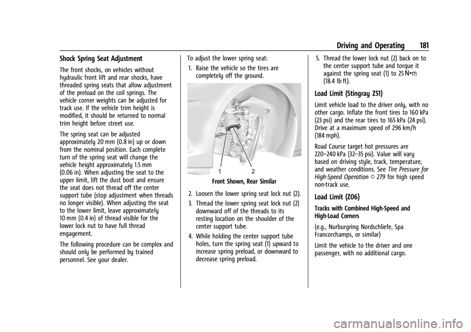
Shock Spring Seat Adjustment
The front shocks, on vehicles without
hydraulic front lift and rear shocks, have
threaded spring seats that allow adjustment
of the preload on the coil springs. The
vehicle corner weights can be adjusted for
track use. If the vehicle trim height is
modified, it should be returned to normal
trim height before street use.
The spring seat can be adjusted
approximately 20 mm (0.8 in) up or down
from the nominal position. Each complete
turn of the spring seat will change the
vehicle height approximately 1.5 mm
(0.06 in). When adjusting the seat to the
upper limit, lift the dust boot and ensure
the seat does not thread off the center
support tube (stop adjustment when threads
no longer visible). When adjusting the seat
to the lower limit, leave approximately
10 mm (0.4 in) of thread visible for the
lower lock nut to have full thread
engagement.
The following procedure can be complex and
should only be performed by trained
personnel. See your dealer.To adjust the lower spring seat:
1. Raise the vehicle so the tires are completely off the ground.
Front Shown, Rear Similar
2. Loosen the lower spring seat lock nut (2).
3. Thread the lower spring seat lock nut (2) downward off of the threads to its
resting location on the shoulder of the
center support tube.
4. While holding the center support tube holes, turn the spring seat (1) upward to
increase spring preload, or downward to
decrease spring preload. 5. Thread the lower lock nut (2) back on to
the center support tube and torque it
against the spring seat (1) to 25 Y
(18.4 lb ft).
Load Limit (Stingray Z51)
Limit vehicle load to the driver only, with no
other cargo. Inflate the front tires to 160 kPa
(23 psi) and the rear tires to 165 kPa (24 psi).
Drive at a maximum speed of 296 km/h
(184 mph).
Road Course target hot pressures are
220–240 kPa (32–35 psi). Value will vary
based on driving style, track, temperature,
and weather conditions. See Tire Pressure for
High-Speed Operation 0279 for high speed
non-track use.
Load Limit (Z06)
Tracks with Combined High-Speed and
High-Load Corners
(e.g., Nurburgring Nordschliefe, Spa
Francorchamps, or similar)
Limit the vehicle to the driver and one
passenger, with no additional cargo.
Page 243 of 351

Chevrolet Corvette Owner Manual (GMNA-Localizing-U.S./Canada/Mexico-
16287457) - 2023 - CRC - 3/10/22
242 Vehicle Care
1. Engine Cooling Fan (Out of View). SeeCooling System 0252.
2. Engine Air Cleaner/Filter (Under Access Panel). See Engine Air Cleaner/Filter
0 251.
3. Dry Sump Engine Oil Tank and Fill Cap. See Engine Oil (5.5L LT6 Engine) 0242 or
Engine Oil (6.2L LT2 Engine) 0245.
4. Engine Oil Dipstick. See Engine Oil (5.5L
LT6 Engine) 0242 or
Engine Oil (6.2L LT2 Engine) 0245.
5. Coolant Surge Tank and Pressure Cap. See Cooling System 0252.
Engine Oil (5.5L LT6 Engine)
To ensure proper engine performance and
long life, pay careful attention to engine oil.
Follow these important steps:
.Use engine oil approved to the proper
specification and of the proper viscosity
grade. See “Selecting the Right Engine
Oil” later in this section.
.Check the engine oil level regularly and
maintain the proper oil level. See
“Checking Engine Oil” and“When to Add
Engine Oil” later in this section.
.Change the engine oil at the appropriate
time. SeeEngine Oil Life System 0248.
.Always dispose of engine oil properly. See
“What to Do with Used Oil” in this
section.
Checking the Engine Oil
1. Engine Oil Dipstick
2. Engine Oil Fill Cap
Check the engine oil level regularly, every
650 km (400 mi), especially prior to a long
trip. To get an accurate reading, the vehicle
must be parked on a level ground.
The engine oil dipstick handle is a loop. See
Engine Compartment Overview 0235 for the
location.
The vehicle has a racetrack-ready dry sump
engine lubrication system. This high
performance system operates differently
than a standard engine lubrication system and requires a special procedure when
checking the engine oil level. Follow this
procedure closely.
The engine oil level must be checked when
the engine is warm. Cold oil level in the dry
sump tank may not indicate the actual
amount of oil in the system. Engine oil is
contained in an external tank, separate from
the engine. Under normal operating
conditions, the oil pan under the engine
does not store any oil. If the vehicle has
been parked for an extended period without
the engine being started, some oil will seep
back into the oil pan. This will reduce the
amount of oil held in the dry sump tank
and there could be no engine oil on the
dipstick. This is normal since the dipstick is
designed to read the engine oil level only
after the engine has run long enough to
reach normal operating temperature. Do not
add engine oil based on cold engine dipstick
readings. The engine oil level on the dipstick
must be checked while the engine is running
at idle.
To check the engine oil:
1. Turn the engine on and let it warm up to at least 80 °C (175 °F).
2. Once the engine is warm, check the oil while the engine is running at idle.