2023 ALFA ROMEO STELVIO lock
[x] Cancel search: lockPage 116 of 268

STARTING AND OPERATING
114
(Continued)
LIMITED SYSTEM AVAILABILITY/
O
PERATION
System Availability
External factors and conditions may affect the
proper operation of HAS, such as:
Narrow, winding, curvy streets
Poor visibility (due to heavy rain, snow, fog,
etc.)
Front lights of oncoming vehicles or direct
sunlight or shade
Damage or obstructions caused by mud, ice,
snow, etc.
Bumper damaged or not aligned
Interference with other equipment that causes
electromagnetic waves
Presence of roadwork/road construction sites
If the indications given by the navigation
system (if any) of the radio system are not yet
ready and/or if the navigation system is
recalculating the route
System Limited Operation
HAS may have limited or reduced functionality
when one of the following conditions occur:
Lane markings are not clear or in conditions of
poor visibility (e.g. in heavy rain, snow,
fog, etc.)
Either the camera or radar are damaged,
covered, or obstructed (e.g. by mud, ice,
snow, etc.)
When driving on hills or roads with narrow
bends
Near highway toll booths
When the highway entrance or exit is wider
than 20 ft (6 m)
If the camera is exposed to glare caused by
reflections or direct sunlight
If the navigation system information is
unavailable or being recalculated
NOTE:
If the vehicle approaches a bend that is too
narrow with respect to the current speed,
HAS will disable.
If damage to the windshield occurs, have the
windshield replaced by an authorized dealer
as soon as possible.
TRAFFIC JAM ASSIST (TJA)
SYSTEM — IF EQUIPPED
The Traffic Jam Assist (TJA) system can be
activated on all road types. The system uses a
camera and radar sensors located on front
fascia/bumper to detect lane markings and keep
the vehicle in the center of the lane.
When the system is unable to detect lane
markings, it will still operate using surrounding
traffic. This can occur in congested traffic
scenarios, when the vehicles ahead or
surroundings obstruct the visibility of the lane
markings. When the speed is below 12 mph
(20 km/h), the system can use a lock-on strategy
that allows the vehicle to automatically follow the
vehicle ahead.
The TJA system combines Adaptive Cruise Control
(ACC) functions with Lane Departure Warning
functions to maintain vehicle speed and steering
wheel behavior.
WARNING!
To prevent serious injury or death:
Always remain alert and be ready to take
control of the vehicle in the event that HAS
disables.
Always keep your hands on the steering
wheel when HAS is activated.
Maintain a safe distance from other vehicles
and pay attention to traffic conditions.
ALWAYS obey traffic laws and pay attention
to the road. ALWAYS drive safely with your
hands on the steering wheel. You have full
responsibility and assume all risks related to
the use of the features and applications in
this vehicle. Only use the features and
applications when it is safe to do so. Failure
to do so may result in an accident involving
serious injury or death.
WARNING!
23_GU_OM_EN_USC_t.book Page 114
Page 131 of 268

129
When enabled in the radio settings, active
guidelines are overlaid on the image to illustrate
the width of the vehicle and its projected back up
path based on the steering wheel position. A
dashed center line overlay indicates the center of
the vehicle to assist in rear parking maneuvers or
trailer hitch alignment. Different colored zones
indicate the distance to the rear of the vehicle.
The following table shows the approximate
distances for each zone:
Messages On The Display
If the liftgate is opened, the camera will not detect
any obstacle behind the vehicle. The display will
show a dedicated warning message.
Make sure the liftgate is closed by pushing next to
the lock until it clicks.Important Notes
Ice, snow or mud on the surface of the camera
may reduce its sensitivity. It is important to
keep the camera surface clean, and free from
debris.
When parking, be aware of obstacles that may
be above or below the camera range.
REFUELING THE VEHICLE
Before refueling, make sure that the fuel type is
correct
Ú
page 249.
Also, stop the engine before refueling.
NOTE:
An inefficient catalytic converter leads to
harmful exhaust emissions, thus contributing to
air pollution.
REFUELING CAPACITY
To ensure that you fill the tank completely, top off
twice after the first click of the fuel nozzle.
Further top-off could cause faults in the fuel
feeding system.
AreaDistance From The
Rear Of The Vehicle
Red 0–11.8 inches
(0–30 cm)
Yellow 11.8 inches to 3.3 feet
(30 cm–1 m)
Green 3.3 feet or more
(1 m or more)
WARNING!
Drivers must be careful when backing up even
when using the Rear Back Up Camera. Always
check carefully behind your vehicle, and be
sure to check for pedestrians, animals, other
vehicles, obstructions, or blind spots before
backing up. You are responsible for the safety
of your surroundings and must continue to pay
attention while backing up. Failure to do so
can result in serious injury or death.
CAUTION!
To avoid vehicle damage, Rear Back Up
Camera should only be used as a parking aid.
The Rear Back Up Camera is unable to view
every obstacle or object in your drive path.
To avoid vehicle damage, the vehicle must
be driven slowly when using the Rear Back
Up Camera to be able to stop in time when an
obstacle is seen. It is recommended that the
driver look frequently over his/her shoulder
when using the Rear Back Up Camera.
CAUTION!
Never introduce leaded fuel to the tank,
even in small amounts in an emergency, as
this would damage the catalytic converter
beyond repair.
23_GU_OM_EN_USC_t.book Page 129
Page 132 of 268
STARTING AND OPERATING
130
REFUELING PROCEDURE
The fuel filler door is unlocked when the central
door locking system is unlocked. It is automat-
ically locked when the central locking system is
applied.
Opening The Fuel Filler Door
To refuel proceed as follows:
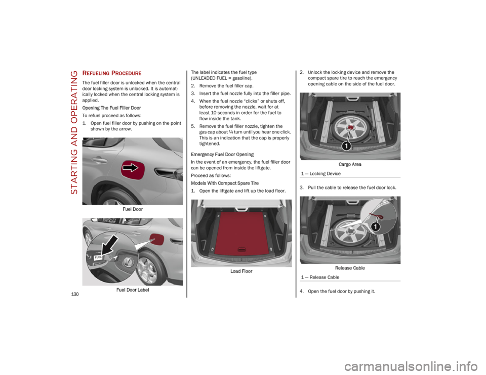
1. Open fuel filler door by pushing on the point shown by the arrow.
Fuel Door
Fuel Door Label The label indicates the fuel type
(UNLEADED FUEL = gasoline).
2. Remove the fuel filler cap.
3. Insert the fuel nozzle fully into the filler pipe.
4. When the fuel nozzle “clicks” or shuts off,
before removing the nozzle, wait for at
least 10 seconds in order for the fuel to
flow inside the tank.
5. Remove the fuel filler nozzle, tighten the gas cap about ¼ turn until you hear one click.
This is an indication that the cap is properly
tightened.
Emergency Fuel Door Opening
In the event of an emergency, the fuel filler door
can be opened from inside the liftgate.
Proceed as follows:
Models With Compact Spare Tire
1. Open the liftgate and lift up the load floor.
Load Floor 2. Unlock the locking device and remove the
compact spare tire to reach the emergency
opening cable on the side of the fuel door.
Cargo Area
3. Pull the cable to release the fuel door lock.
Release Cable
4. Open the fuel door by pushing it.
1 — Locking Device
1 — Release Cable
23_GU_OM_EN_USC_t.book Page 130
Page 133 of 268
131
Models Without Compact Spare Tire
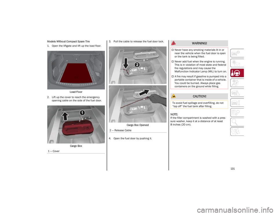
1. Open the liftgate and lift up the load floor.Load Floor
2. Lift up the cover to reach the emergency opening cable on the side of the fuel door.
Cargo Box 3. Pull the cable to release the fuel door lock.
Cargo Box Opened
4. Open the fuel door by pushing it.
NOTE:
If the filler compartment is washed with a pres -
sure washer, keep it at a distance of at least
8 inches (20 cm).
1 — Cover
2 — Release Cable
WARNING!
Never have any smoking materials lit in or
near the vehicle when the fuel door is open
or the tank is being filled.
Never add fuel when the engine is running.
This is in violation of most state and federal
fire regulations and may cause the
Malfunction Indicator Lamp (MIL) to turn on.
A fire may result if gasoline is pumped into a
portable container that is inside of a vehicle.
You could be burned. Always place gas
containers on the ground while filling.
CAUTION!
To avoid fuel spillage and overfilling, do not
“top off” the fuel tank after filling.
23_GU_OM_EN_USC_t.book Page 131
Page 137 of 268
135
(Continued)
(Continued)
TRAILER AND TONGUE WEIGHT
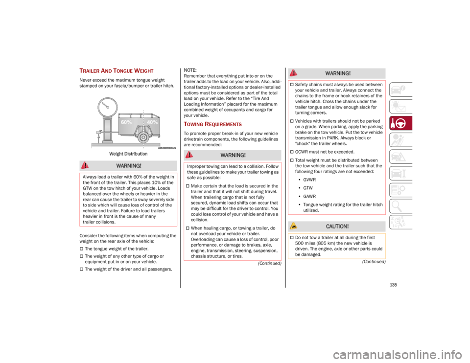
Never exceed the maximum tongue weight
stamped on your fascia/bumper or trailer hitch.
Weight Distribution
Consider the following items when computing the
weight on the rear axle of the vehicle:
The tongue weight of the trailer.
The weight of any other type of cargo or
equipment put in or on your vehicle.
The weight of the driver and all passengers.
NOTE:
Remember that everything put into or on the
trailer adds to the load on your vehicle. Also, addi -
tional factory-installed options or dealer-installed
options must be considered as part of the total
load on your vehicle. Refer to the “Tire And
Loading Information” placard for the maximum
combined weight of occupants and cargo for
your vehicle.
TOWING REQUIREMENTS
To promote proper break-in of your new vehicle
drivetrain components, the following guidelines
are recommended:
WARNING!
Always load a trailer with 60% of the weight in
the front of the trailer. This places 10% of the
GTW on the tow hitch of your vehicle. Loads
balanced over the wheels or heavier in the
rear can cause the trailer to sway severely side
to side which will cause loss of control of the
vehicle and trailer. Failure to load trailers
heavier in front is the cause of many
trailer collisions.
WARNING!
Improper towing can lead to a collision. Follow
these guidelines to make your trailer towing as
safe as possible:
Make certain that the load is secured in the
trailer and that it will not shift during travel.
When trailering cargo that is not fully
secured, dynamic load shifts can occur that
may be difficult for the driver to control. You
could lose control of your vehicle and have a
collision.
When hauling cargo, or towing a trailer, do
not overload your vehicle or trailer.
Overloading can cause a loss of control, poor
performance, or damage to brakes, axle,
engine, transmission, steering, suspension,
chassis structure, or tires.
Safety chains must always be used between
your vehicle and trailer. Always connect the
chains to the frame or hook retainers of the
vehicle hitch. Cross the chains under the
trailer tongue and allow enough slack for
turning corners.
Vehicles with trailers should not be parked
on a grade. When parking, apply the parking
brake on the tow vehicle. Put the tow vehicle
transmission in PARK. Always block or
"chock" the trailer wheels.
GCWR must not be exceeded.
Total weight must be distributed between
the tow vehicle and the trailer such that the
following four ratings are not exceeded:
• GVWR
• GTW
• GAWR
• Tongue weight rating for the trailer hitch
utilized.
CAUTION!
Do not tow a trailer at all during the first
500 miles (805 km) the new vehicle is
driven. The engine, axle or other parts could
be damaged.
WARNING!
23_GU_OM_EN_USC_t.book Page 135
Page 139 of 268

137
Four-Pin Connector
Seven-Pin Connector
TOWING TIPS
Before setting out on a trip, practice turning,
stopping, and backing up the trailer in an area
located away from heavy traffic.
Automatic Transmission
Select the DRIVE range when towing. The
transmission controls include a drive strategy to
avoid frequent shifting when towing. However, if
frequent shifting does occur while in DRIVE, you
can use the AutoStick shift control to manually
select a lower gear.
NOTE:
Using a lower gear while operating the vehicle
under heavy loading conditions will improve
performance and extend transmission life by
reducing excessive shifting and heat buildup. This
action will also provide better engine braking.
Cruise Control — If Equipped
Do not use on hilly terrain or with heavy loads.
When using the Cruise Control, if you
experience speed drops greater than 10 mph
(16 km/h), disengage until you can get back to
cruising speed.
Use Cruise Control in flat terrain and with light
loads to maximize fuel efficiency.
INSTALLING THE RECEIVER
To properly install the receiver, see the following
directions:
1. Retrieve the receiver from the luggage compartment.
2. Push the receiver into the trailer hitch, and secure by inserting the locking pin into the
trailer hitch.
3. Insert the safety split ring into the hole on the locking pin.
NOTE:
Ensure that the locking pin is removed from the
trailer hitch before installing the receiver.
Trailer Hitch And Receiver
1 — Ground
2 — Park
3 — Left Stop/Turn
4 — Right Stop/Turn
1 — Backup Lamps
2 — Running Lamps
3 — Left Stop/Turn
4 — Ground
5 — Battery
6 — Right Stop/Turn
7 — Electric Brakes
1 – Receiver
2 – Locking Pin
3 – Safety Split Ring
A – Trailer Hitch
23_GU_OM_EN_USC_t.book Page 137
Page 140 of 268
STARTING AND OPERATING
138
CONNECTING THE ELECTRICAL SYSTEM
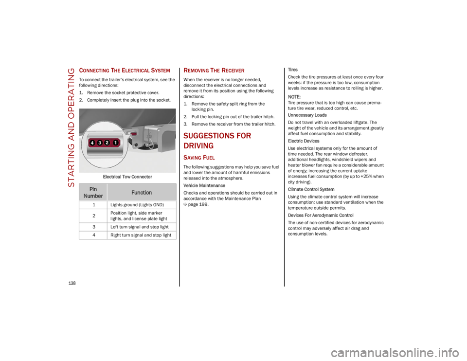
To connect the trailer’s electrical system, see the
following directions:
1. Remove the socket protective cover.
2. Completely insert the plug into the socket.Electrical Tow Connector
REMOVING THE RECEIVER
When the receiver is no longer needed,
disconnect the electrical connections and
remove it from its position using the following
directions:
1. Remove the safety split ring from thelocking pin.
2. Pull the locking pin out of the trailer hitch.
3. Remove the receiver from the trailer hitch.
SUGGESTIONS FOR
DRIVING
SAVING FUEL
The following suggestions may help you save fuel
and lower the amount of harmful emissions
released into the atmosphere.
Vehicle Maintenance
Checks and operations should be carried out in
accordance with the Maintenance Plan
Ú
page 199. Tires
Check the tire pressures at least once every four
weeks: if the pressure is too low, consumption
levels increase as resistance to rolling is higher.
NOTE:
Tire pressure that is too high can cause prema
-
ture tire wear, reduced control, etc.
Unnecessary Loads
Do not travel with an overloaded liftgate. The
weight of the vehicle and its arrangement greatly
affect fuel consumption and stability.
Electric Devices
Use electrical systems only for the amount of
time needed. The rear window defroster,
additional headlights, windshield wipers and
heater blower fan require a considerable amount
of energy; increasing the current uptake
increases fuel consumption (by up to +25% when
city driving).
Climate Control System
Using the climate control system will increase
consumption: use standard ventilation when the
temperature outside permits.
Devices For Aerodynamic Control
The use of non-certified devices for aerodynamic
control may adversely affect air drag and
consumption levels.
Pin
NumberFunction
1 Lights ground (Lights GND)
2 Position light, side marker
lights, and license plate light
3 Left turn signal and stop light
4 Right turn signal and stop light
23_GU_OM_EN_USC_t.book Page 138
Page 142 of 268
140
(Continued)
SAFETY
This very important section describes the safety
systems that your vehicle may be equipped with,
and provides instructions on how to use them
correctly.
ACTIVE SAFETY SYSTEMS
The vehicle may be equipped with the following
active safety devices:
Anti-Lock Brake System (ABS)
Active Torque Vectoring (ATV) System
Dynamic Steering Torque (DST) System
Drive Train Control (DTC) System
Electronic Stability Control (ESC) System
Hill Descent Control (HDC) System
Hill Start Assist (HSA) System
Panic Brake Assist (PBA) System
Traction Control System (TCS)
For system operation, see the following pages.
ANTI-LOCK BRAKE SYSTEM (ABS)
An integral part of the braking system, the ABS
prevents one or more wheels from locking and
slipping in all road surface conditions, regardless
of the intensity of the braking action. The system
ensures that the vehicle can be controlled even
during emergency braking, allowing the driver to
optimize stopping distances.
The system intervenes during braking when the
wheels are about to lock, typically in emergency
braking or low-grip conditions where locking may
be more frequent. The system also improves control and stability of
the vehicle when braking on a surface where the
grip of the left and right wheels varies, such as in
a corner.
The Electronic Braking Force Distribution (EBD)
system works with the ABS, allowing the brake
force to be distributed between the front and rear
wheels.
System Intervention
The ABS equipped on this vehicle is provided with
the "Brake-By-Wire", Integrated Brake System
(IBS), function. With this system, the command
given by pressing the brake pedal is not
transmitted hydraulically, but electrically.
Therefore, the light pulsation that is felt on the
pedal with the traditional system is no longer
noticeable.
ACTIVE TORQUE VECTORING (ATV)
S
YSTEM — IF EQUIPPED
The dynamic drive control is used to optimize and
balance the drive torque between the wheels of
the same axles. The ATV system improves the grip
in turns, sending more drive torque to the
external wheel.
Given that, in a turn, the external wheels of the
car travel more than the internal ones and
therefore turn faster, sending a higher thrust to
the external rear wheel allows for the car to be
more stable and to not suffer an "understeer"
condition. Understeer occurs when the vehicle is
turning less than appropriate for the steering
wheel position.
WARNING!
The ABS contains sophisticated electronic
equipment that may be susceptible to
interference caused by improperly installed
or high output radio transmitting equipment.
This interference can cause possible loss of
anti-lock braking capability. Installation of
such equipment should be performed by
qualified professionals.
Pumping of the Anti-Lock Brakes will
diminish their effectiveness and may lead to
a collision. Pumping makes the stopping
distance longer. Just press firmly on your
brake pedal when you need to slow down or
stop.
The ABS cannot prevent the natural laws of
physics from acting on the vehicle, nor can it
increase braking or steering efficiency
beyond that afforded by the condition of the
vehicle brakes and tires or the traction
afforded.
The ABS cannot prevent collisions, including
those resulting from excessive speed in
turns, following another vehicle too closely,
or hydroplaning.
The capabilities of an ABS equipped vehicle
must never be exploited in a reckless or
dangerous manner that could jeopardize the
user’s safety or the safety of others.
WARNING!
23_GU_OM_EN_USC_t.book Page 140