2023 ALFA ROMEO STELVIO lock
[x] Cancel search: lockPage 55 of 268

53
At low external temperatures or in high humidity,
the automatic function turns off to avoid fogging
up the windows. The user can select the function
again by pushing the Air Recirculation Button.
In automatic operation, air recirculation will be
controlled by the system according to outside
environmental conditions.
NOTE:
With the AQS function active and after the
internal air recirculation system has been
functioning for a set amount of time, the
Climate Control System enables air intake to
cycle the air in the passenger compartment for
a set time. The AQS function is disabled during
the air changes.
The engagement of the recirculation system
makes it possible to reach the required heating
or cooling conditions faster. It is, however,
inadvisable to use it on rainy/cold days as it
can increase the possibility of the windows
fogging. When the outside temperature is low,
recirculation is forced off to prevent the
windows from fogging up.
Front Defrost Air comes from the windshield and side
window demist outlets. Use Defrost
mode with maximum temperature
settings for best windshield and side
window defrosting and defogging.
Rear Defrost
Push the Rear Defrost button to activate
(indicators illuminated) the Rear
Defroster. The Rear Defrost will turn off after 20 minutes or
once the engine is turned off.
NOTE:
To avoid damage, do not apply stickers over the
interior heating filaments of the Rear Defroster.
Front Defrost And MAX-DEF Function
Push the MAX-DEF button (indicator
illuminated) to defrost the windshield
and side windows.
While in MAX-DEF function, the air conditioner
will:
Activate the air conditioner compressor when
the weather allows
Turn air recirculation off
Set the maximum air temperature (HI) on both
the driver and passenger side
Activate a blower speed based on the
temperature of the engine coolant
Adjust the air flow towards the windshield and
front side windows
Activate the Rear Window Defrost
Display the fan speed (indicators illuminated)
and current air distribution setting
NOTE:
The MAX-DEF function remains active for approx -
imately three minutes once the engine coolant
reaches the proper temperature.
When the function is on, AUTO mode will
deactivate. The only manual operations possible
are adjusting blower speed and turning off the
Rear Window Defrost. Pushing the Air Recirculation button switches
off the MAX-DEF function.
Air Temperature Adjustment
Rotate the driver or passenger Temperature
Adjustment Knob clockwise for warmer
temperatures or counterclockwise for cooler
temperatures. The set temperatures are shown
on the radio system.
Push the SYNC button to sync the driver and
passenger air temperatures.
Rotate the passenger Temperature Adjustment
Knob to cancel the SYNC function. This will set a
new passenger side temperature.
Rotate the Temperature Adjustment Knob fully
clockwise to engage the HI (maximum heating)
setting or fully counterclockwise to engage the
LO (maximum cooling) setting. To deactivate
these functions, rotate the Temperature
Adjustment Knob to the desired temperature.
Rear passengers’ temperature is linked to driver
side selection.
AUTO Button
When the AUTO button is pushed (indicator
illuminated), the Climate Control system automat
-
ically adjusts the following settings:Quantity and distribution of air flow in the
passenger compartment
The air conditioner
Air recirculation
Cancels any manual settings
Selecting the AUTO function illuminates the
indicator on the A/C button.
23_GU_OM_EN_USC_t.book Page 53
Page 56 of 268

GETTING TO KNOW YOUR VEHICLE
54
If air distribution or the fan speed is manually
adjusted, the AUTO button indicator will turn off to
indicate that the Climate Control system is no
longer in AUTO mode.
After a manual adjustment, push the AUTO
button to resume the automatic system.
SYNC Button
Push the SYNC button (indicator illuminated) to
sync the passenger side air temperature with the
driver side air temperature.
This function makes temperature regulation
easier when the driver is traveling alone.
Turn the passenger Temperature Adjustment
Knob or push the passenger side Air Distribution
Selection Button to change the passenger side
air temperature and return to separate air
temperature management.
Blower Speed
Turn the Blower Speed Knob to increase or
decrease the blower speed. The speed is
displayed with lighted indicators in the radio
system display.
Maximum fan speed = all indicators
illuminated on the radio system display
Minimum fan speed = one indicator
illuminated on the radio system display
The fan can be turned off by rotating the Blower
Speed Knob counterclockwise to the off position
(all segments on the radio system display are
turned off).
NOTE:
To restore automatic control of the fan speed,
push the AUTO button. Air Distribution Selection
Push the Air Distribution Selection button on the
faceplate to change the mode of air distribution.
NOTE:
In AUTO mode, the Climate Controls automati
-
cally manage the air distribution. When set manu -
ally, the respective symbols on the radio system
indicate the air distribution setting.
Panel Mode
Air comes from the outlets in the
instrument panel to ventilate the chest
and face. Each of these outlets can be
individually adjusted to direct the flow of
air. The air vanes of the center outlets and
outboard outlets can be moved up and down or
side to side to regulate airflow direction. There is
a shut-off wheel located below the air vanes to
shut off or adjust the amount of airflow from
these outlets.
Bi-Level Mode
Air comes from the instrument panel
outlets and floor outlets. A slight amount
of air is directed through the defrost and
side window demister outlets.
NOTE:
Bi-Level mode is designed under comfort condi -
tions to provide cooler air out of the panel outlets
and warmer air from the floor outlets.
Floor Mode
Air comes from the floor outlets. A slight
amount of air is directed through the
defrost and side window demister
outlets. This setting heats the
passenger compartment the quickest. Mix Mode
Air is directed through the floor, defrost,
and side window demister outlets. This
setting works best in cold or snowy
conditions that require extra heat to the
windshield. This setting is good for maintaining
comfort while reducing moisture on the
windshield.
Front Defrost And Panel Mode
Air flow is distributed between the
windshield demisting/defrosting vents
and side/central dashboard vents.
This setting allows air to flow to the
windshield on sunny days.
Front Defrost And Bi-Level Mode
Air flow is distributed to all vents.
Switching The Climate Control System On/Off
To Turn Off The Climate Control System
Rotate the Air Speed Adjustment Knob
completely counterclockwise to turn off the
Climate Control system.
When the air conditioner is off:Air recirculation is on
The A/C compressor is off
The fan is off
The heated rear window can be activated/
deactivated
NOTE:
The Climate Control system stores the previously
set temperatures and resumes operation when
any button on the system is pushed.
23_GU_OM_EN_USC_t.book Page 54
Page 58 of 268

GETTING TO KNOW YOUR VEHICLE
56
INTERIOR STORAGE AND
EQUIPMENT
GLOVE COMPARTMENT
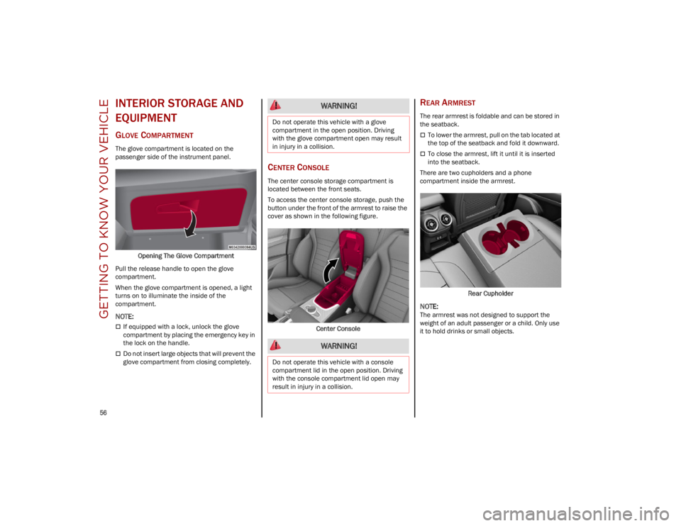
The glove compartment is located on the
passenger side of the instrument panel.Opening The Glove Compartment
Pull the release handle to open the glove
compartment.
When the glove compartment is opened, a light
turns on to illuminate the inside of the
compartment.
NOTE:
If equipped with a lock, unlock the glove
compartment by placing the emergency key in
the lock on the handle.
Do not insert large objects that will prevent the
glove compartment from closing completely.
CENTER CONSOLE
The center console storage compartment is
located between the front seats.
To access the center console storage, push the
button under the front of the armrest to raise the
cover as shown in the following figure.
Center Console
REAR ARMREST
The rear armrest is foldable and can be stored in
the seatback.
To lower the armrest, pull on the tab located at
the top of the seatback and fold it downward.
To close the armrest, lift it until it is inserted
into the seatback.
There are two cupholders and a phone
compartment inside the armrest.
Rear Cupholder
NOTE:
The armrest was not designed to support the
weight of an adult passenger or a child. Only use
it to hold drinks or small objects.
WARNING!
Do not operate this vehicle with a glove
compartment in the open position. Driving
with the glove compartment open may result
in injury in a collision.
WARNING!
Do not operate this vehicle with a console
compartment lid in the open position. Driving
with the console compartment lid open may
result in injury in a collision.
23_GU_OM_EN_USC_t.book Page 56
Page 60 of 268

GETTING TO KNOW YOUR VEHICLE
58
CIGAR LIGHTER AND ASH TRAY —
I
F EQUIPPED
If equipped, the cigar lighter is located on the
bottom of the center stack, in front of the
cupholders.
To activate the cigar lighter, push in and wait a
few seconds. Once the cigar lighter has returned
to its original position, it is ready for use.
NOTE:
Always ensure the cigar lighter is turned off when
not in use.
1 — Cigar Lighter
If equipped, the ash tray is a removable plastic
container located inside the cupholder.
WIRELESS CHARGING PAD —
I
F EQUIPPED
Wireless Charging Pad
Your vehicle may be equipped with a 15 W (3 A)
Qi wireless charging pad located inside of the
center console. This charging pad is designed to
wirelessly charge your Qi enabled mobile phone.
Qi is a standard that uses magnetic induction to
transfer power to your mobile device.
Your mobile phone must be designed for
Qi wireless charging.
NOTE:
Do not place the key fob or any other type of
metal/magnetized object inside the mobile
phone housing or near the wireless charging
pad.
Be sure to place the mobile device correctly
(display facing upward) on the wireless
charging pad.
The ignition must be in the ON/RUN position in
order for the phone to charge.
To avoid interference with the key fob search,
the wireless charging pad will stop charging
when any door is opened.
The following messages will display in the radio
system:
“Your phone is being charged” — The phone
has begun to charge.
“Phone Fully Charged” — The phone has
completed charging its battery.
“Foreign Object Detected” — The phone is not
enabled for wireless charging or an object that
is not permitted has been placed on the
wireless charging pad.
“Unavailable System” — There is a malfunction
with the wireless charging pad.
The driver can deactivate these messages
through the radio system. Refer to the
Information and Entertainment System Owner’s
Manual Supplement for further information.
CAUTION!
The key fob should not be placed on the
charging pad or within 6 inches (15 cm) of it.
Doing so can cause excessive heat buildup
and damage to the fob. Placing the fob in
close proximity of the charging pad blocks the
fob from being detected by the vehicle and
prevents the vehicle from starting.
23_GU_OM_EN_USC_t.book Page 58
Page 61 of 268

59
POWER WINDOWS
POWER WINDOW CONTROLS
The power window switches work with the ignition
in the ACC or ON/RUN position and for three
minutes after the ignition has been placed in the
OFF position. When one of the front doors is
opened, this operation is disabled.
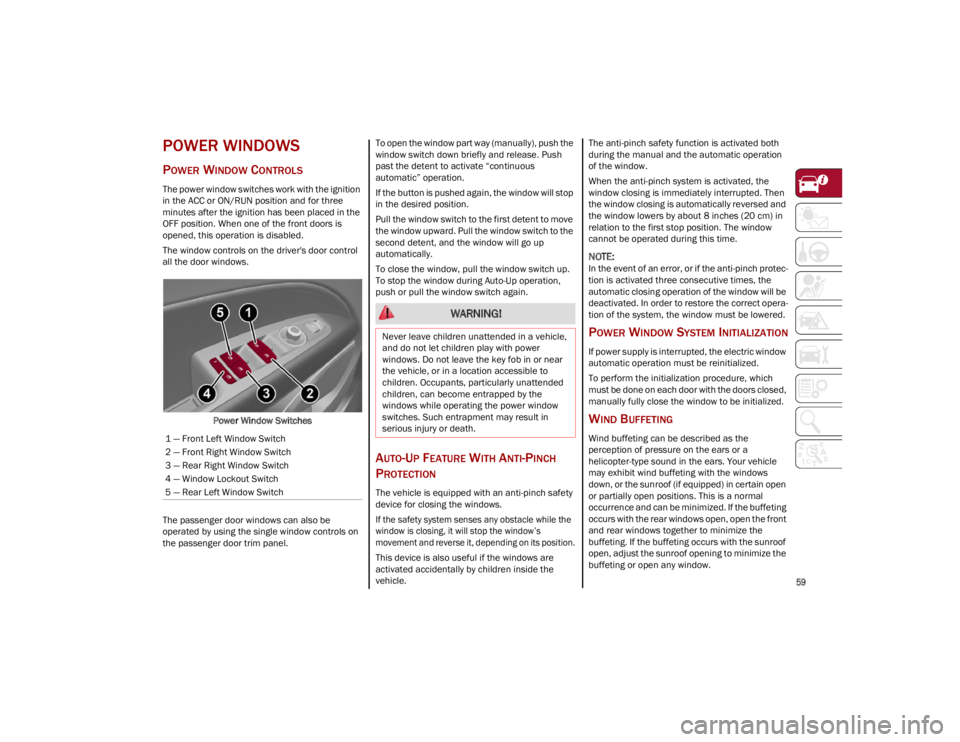
The window controls on the driver's door control
all the door windows.Power Window Switches
The passenger door windows can also be
operated by using the single window controls on
the passenger door trim panel. To open the window part way (manually), push the
window switch down briefly and release. Push
past the detent to activate “continuous
automatic” operation.
If the button is pushed again, the window will stop
in the desired position.
Pull the window switch to the first detent to move
the window upward. Pull the window switch to the
second detent, and the window will go up
automatically.
To close the window, pull the window switch up.
To stop the window during Auto-Up operation,
push or pull the window switch again.
AUTO-UP FEATURE WITH ANTI-PINCH
P
ROTECTION
The vehicle is equipped with an anti-pinch safety
device for closing the windows.
If the safety system senses any obstacle while the
window is closing, it will stop the window’s
movement and reverse it, depending on its position.
This device is also useful if the windows are
activated accidentally by children inside the
vehicle. The anti-pinch safety function is activated both
during the manual and the automatic operation
of the window.
When the anti-pinch system is activated, the
window closing is immediately interrupted. Then
the window closing is automatically reversed and
the window lowers by about 8 inches (20 cm) in
relation to the first stop position. The window
cannot be operated during this time.
NOTE:
In the event of an error, or if the anti-pinch protec
-
tion is activated three consecutive times, the
automatic closing operation of the window will be
deactivated. In order to restore the correct opera -
tion of the system, the window must be lowered.
POWER WINDOW SYSTEM INITIALIZATION
If power supply is interrupted, the electric window
automatic operation must be reinitialized.
To perform the initialization procedure, which
must be done on each door with the doors closed,
manually fully close the window to be initialized.
WIND BUFFETING
Wind buffeting can be described as the
perception of pressure on the ears or a
helicopter-type sound in the ears. Your vehicle
may exhibit wind buffeting with the windows
down, or the sunroof (if equipped) in certain open
or partially open positions. This is a normal
occurrence and can be minimized. If the buffeting
occurs with the rear windows open, open the front
and rear windows together to minimize the
buffeting. If the buffeting occurs with the sunroof
open, adjust the sunroof opening to minimize the
buffeting or open any window.
1 — Front Left Window Switch
2 — Front Right Window Switch
3 — Rear Right Window Switch
4 — Window Lockout Switch
5 — Rear Left Window Switch
WARNING!
Never leave children unattended in a vehicle,
and do not let children play with power
windows. Do not leave the key fob in or near
the vehicle, or in a location accessible to
children. Occupants, particularly unattended
children, can become entrapped by the
windows while operating the power window
switches. Such entrapment may result in
serious injury or death.
23_GU_OM_EN_USC_t.book Page 59
Page 62 of 268

GETTING TO KNOW YOUR VEHICLE
60
(Continued)
POWER SUNROOF —
IF EQUIPPED
POWER SUNROOF
The power sunroof consists of a single glass
panel and is fitted with a power sunshade the full
length of the panel.
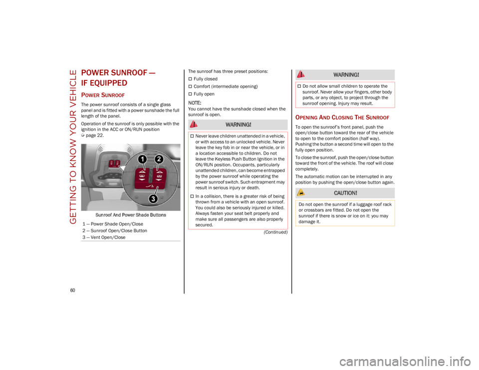
Operation of the sunroof is only possible with the
ignition in the ACC or ON/RUN position
Ú
page 22.Sunroof And Power Shade Buttons The sunroof has three preset positions:
Fully closed
Comfort (intermediate opening)
Fully open
NOTE:
You cannot have the sunshade closed when the
sunroof is open.
OPENING AND CLOSING THE SUNROOF
To open the sunroof’s front panel, push the
open/close button toward the rear of the vehicle
to open to the comfort position (half way).
Pushing the button a second time will open to the
fully open position.
To close the sunroof, push the open/close button
toward the front of the vehicle. The roof will close
completely.
The automatic motion can be interrupted in any
position by pushing the open/close button again.
1 — Power Shade Open/Close
2 — Sunroof Open/Close Button
3 — Vent Open/Close WARNING!
Never leave children unattended in a vehicle,
or with access to an unlocked vehicle. Never
leave the key fob in or near the vehicle, or in
a location accessible to children. Do not
leave the Keyless Push Button Ignition in the
ON/RUN position. Occupants, particularly
unattended children, can become entrapped
by the power sunroof while operating the
power sunroof switch. Such entrapment may
result in serious injury or death.
In a collision, there is a greater risk of being
thrown from a vehicle with an open sunroof.
You could also be seriously injured or killed.
Always fasten your seat belt properly and
make sure all passengers are also properly
secured.
Do not allow small children to operate the
sunroof. Never allow your fingers, other body
parts, or any object, to project through the
sunroof opening. Injury may result.
CAUTION!
Do not open the sunroof if a luggage roof rack
or crossbars are fitted. Do not open the
sunroof if there is snow or ice on it: you may
damage it.
WARNING!
23_GU_OM_EN_USC_t.book Page 60
Page 64 of 268

GETTING TO KNOW YOUR VEHICLE
62
HOOD
OPENING THE HOOD
To open the hood, two latches must be released.
1. Pull the release lever located underneath the driver’s side of the instrument panel.
Hood Release Lever
2. Lift the hood slightly. Move the underhood latch from right to left to release the hood.
Hood Latch Location 3. Raise the hood completely. The operation is
assisted by the addition of two gas props
which hold it in the open position.
NOTE:
Use both hands to lift the hood. Before lifting,
check that the windshield wiper arms are not
raised from the windshield or in operation.
CLOSING THE HOOD
To close, lower the hood to approximately
16 inches (40 cm) from the engine compartment
then let it drop. Make sure that the hood is
completely closed and fully latched.
NOTE:
Since the hood is equipped with a double locking
system, one for each side, you must check that it
is closed on each side.
POWER LIFTGATE
Unlocking of the liftgate is electrically operated
and is deactivated when the vehicle is in motion.
If anything obstructs the power liftgate while it is
closing or opening, the liftgate will automatically
reverse to the closed or open position, provided it
meets sufficient resistance.
OPENING
The liftgate may be released in several ways:
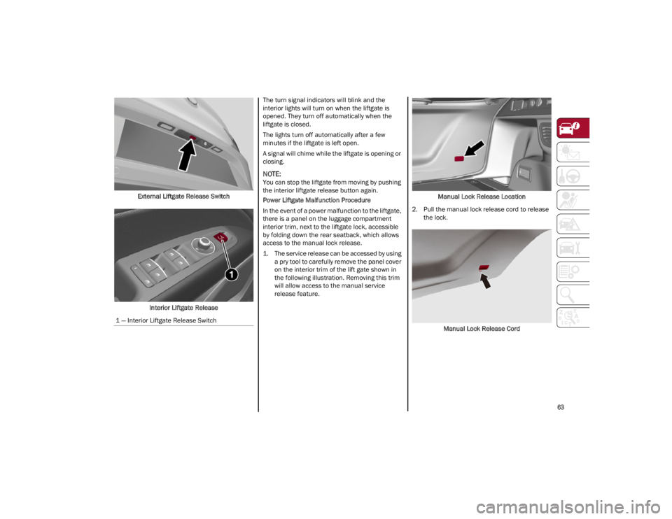
Pressing the liftgate release button on the
key fob twice within five seconds
Pushing the external liftgate release switch
(when the liftgate is unlocked)
Lifting the interior liftgate release button on
the driver’s door panel trim
WARNING!
Before opening the hood, apply the Electric
Park Brake (EPB) and place the gear selector
in PARK. Otherwise the vehicle may roll and
cause damage, serious injury, or death.
CAUTION!
Do not tamper with the gas props.
WARNING!
Be sure the hood is fully latched before driving
your vehicle. If the hood is not fully latched, it
could open when the vehicle is in motion and
block your vision. Failure to follow this warning
could result in serious injury or death.
23_GU_OM_EN_USC_t.book Page 62
Page 65 of 268

63
External Liftgate Release SwitchInterior Liftgate Release The turn signal indicators will blink and the
interior lights will turn on when the liftgate is
opened. They turn off automatically when the
liftgate is closed.
The lights turn off automatically after a few
minutes if the liftgate is left open.
A signal will chime while the liftgate is opening or
closing.
NOTE:
You can stop the liftgate from moving by pushing
the interior liftgate release button again.
Power Liftgate Malfunction Procedure
In the event of a power malfunction to the liftgate,
there is a panel on the luggage compartment
interior trim, next to the liftgate lock, accessible
by folding down the rear seatback, which allows
access to the manual lock release.
1. The service release can be accessed by using
a pry tool to carefully remove the panel cover
on the interior trim of the lift gate shown in
the following illustration. Removing this trim
will allow access to the manual service
release feature. Manual Lock Release Location
2. Pull the manual lock release cord to release the lock.
Manual Lock Release Cord
1 — Interior Liftgate Release Switch
23_GU_OM_EN_USC_t.book Page 63