2023 ALFA ROMEO STELVIO battery
[x] Cancel search: batteryPage 187 of 268

185
(Continued)
(Continued)
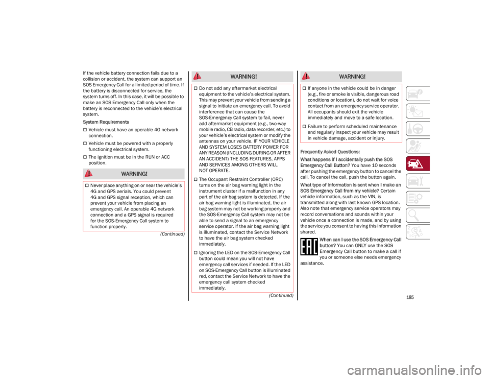
If the vehicle battery connection fails due to a
collision or accident, the system can support an
SOS Emergency Call for a limited period of time. If
the battery is disconnected for service, the
system turns off. In this case, it will be possible to
make an SOS Emergency Call only when the
battery is reconnected to the vehicle’s electrical
system.
System Requirements
Vehicle must have an operable 4G network
connection.
Vehicle must be powered with a properly
functioning electrical system.
The ignition must be in the RUN or ACC
position.
Frequently Asked Questions:
What happens if I accidentally push the SOS
Emergency Call Button?
You have 10 seconds
after pushing the emergency button to cancel the
call. To cancel the call, push the button again.
What type of information is sent when I make an
SOS Emergency Call from my vehicle? Certain
vehicle information, such as the VIN, is
transmitted along with last known GPS location.
Also note that emergency service operators may
record conversations and sounds within your
vehicle once a connection is made, and by using
the service you consent to having this information
shared.
When can I use the SOS Emergency Call
button? You can ONLY use the SOS
Emergency Call button to make a call if
you or someone else needs emergency
assistance.
WARNING!
Never place anything on or near the vehicle’s
4G and GPS aerials. You could prevent
4G and GPS signal reception, which can
prevent your vehicle from placing an
emergency call. An operable 4G network
connection and a GPS signal is required
for the SOS-Emergency Call system to
function properly.
Do not add any aftermarket electrical
equipment to the vehicle’s electrical system.
This may prevent your vehicle from sending a
signal to initiate an emergency call. To avoid
interference that can cause the
SOS-Emergency Call system to fail, never
add aftermarket equipment (e.g., two-way
mobile radio, CB radio, data recorder, etc.) to
your vehicle’s electrical system or modify the
antennas on your vehicle. IF YOUR VEHICLE
AND SYSTEM LOSES BATTERY POWER FOR
ANY REASON (INCLUDING DURING OR AFTER
AN ACCIDENT) THE SOS FEATURES, APPS
AND SERVICES AMONG OTHERS WILL
NOT OPERATE.
The Occupant Restraint Controller (ORC)
turns on the air bag warning light in the
instrument cluster if a malfunction in any
part of the air bag system is detected. If the
air bag warning light is illuminated, the air
bag system may not be working properly and
the SOS-Emergency Call system may not be
able to send a signal to an emergency
service operator. If the air bag warning light
is illuminated, contact the Service Network
to have the air bag system checked
immediately.
Ignoring the LED on the SOS-Emergency Call
button could mean you will not have
emergency call services if needed. If the LED
on SOS-Emergency Call button is illuminated
red, contact the Service Network to have the
emergency call system checked
immediately.
WARNING!
If anyone in the vehicle could be in danger
(e.g., fire or smoke is visible, dangerous road
conditions or location), do not wait for voice
contact from an emergency service operator.
All occupants should exit the vehicle
immediately and move to a safe location.
Failure to perform scheduled maintenance
and regularly inspect your vehicle may result
in vehicle damage, accident or injury.
WARNING!
23_GU_OM_EN_USC_t.book Page 185
Page 194 of 268

IN CASE OF EMERGENCY
192
4. Start the compressor by putting the power switch to I (on). As soon as the correct pres -
sure is reached, put the power switch to
O (off).
Air Compressor And Components
If the tire is overinflated, reduce the pressure by
pushing the PSI/BAR button and releasing it
when the correct pressure is reached.
JUMP STARTING
If your vehicle has a discharged battery, it can be
jump started from the remote battery
connections by using a set of jumper cables and
a battery in another vehicle, or by using a
portable battery booster pack. Jump starting can
be dangerous if done improperly, so please follow
the procedures in this section carefully.
NOTE:
When using a portable battery booster pack,
follow the manufacturer's operating instructions
and precautions.
REMOTE BATTERY CONNECTION POSTS
Your vehicle is equipped with remote battery
connection posts for jump starting. Depending
on the vehicle model, remote post locations
may vary.
Non Quadrifoglio Model
The remote jump starting battery posts can be
found inside the engine compartment.
Remote Battery Post Locations
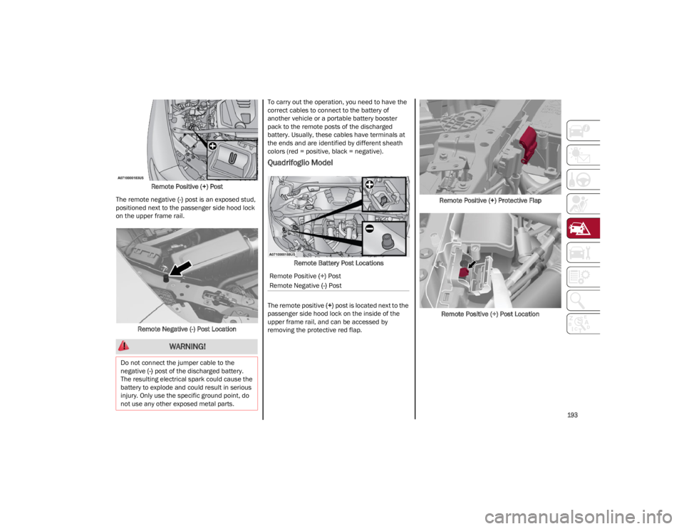
The remote positive (+) post is located above the
engine stabilizer bar, which can be accessed by
opening the spring loaded protective red flap.
Remote Positive (+) Protective Flap
5 — Hose
7 — Power Switch
8 — Pressure Gauge
9 — PSI/BAR Button
WARNING!
Do not attempt jump starting if the battery is
frozen. It could rupture or explode and cause
personal injury.
CAUTION!
Do not use the battery for jump starting the
vehicle. Improperly connecting the jumper
cables or booster pack to the battery can
result in electrical system and fuse failure.
Always use the remote battery connection
posts to jump start your vehicle.
Do not use a portable battery booster pack or
any other booster source with a system
voltage greater than 12 Volts or damage to
the battery, starter motor, alternator or
electrical system may occur.
Remote Positive (+) Post
Remote Negative (-) Post
23_GU_OM_EN_USC_t.book Page 192
Page 195 of 268

193
Remote Positive (+) Post
The remote negative (-) post is an exposed stud,
positioned next to the passenger side hood lock
on the upper frame rail.
Remote Negative (-) Post Location To carry out the operation, you need to have the
correct cables to connect to the battery of
another vehicle or a portable battery booster
pack to the remote posts of the discharged
battery. Usually, these cables have terminals at
the ends and are identified by different sheath
colors (red = positive, black = negative).
Quadrifoglio Model
Remote Battery Post Locations
The remote positive (+) post is located next to the
passenger side hood lock on the inside of the
upper frame rail, and can be accessed by
removing the protective red flap. Remote Positive (+) Protective Flap
Remote Positive (+) Post Location
WARNING!
Do not connect the jumper cable to the
negative (-) post of the discharged battery.
The resulting electrical spark could cause the
battery to explode and could result in serious
injury. Only use the specific ground point, do
not use any other exposed metal parts.
Remote Positive (+) Post
Remote Negative (-) Post
23_GU_OM_EN_USC_t.book Page 193
Page 196 of 268

IN CASE OF EMERGENCY
194
The remote negative (-) post is an exposed stud,
positioned next to the passenger side hood lock
on the upper frame rail.
Remote Negative (-) Post Location
To carry out the operation, you need to have the
correct cables to connect to the battery of
another vehicle or a portable battery booster
pack to the remote posts of the discharged
battery. Usually, these cables have terminals at
the ends and are identified by different sheath
colors (red = positive, black = negative).JUMP STARTING PROCEDURE
Preparation For Jump Starting:
1. Firmly apply the park brake, and cycle the ignition to OFF.
2. Turn off all electrical features in the vehicle.
3. If using another vehicle to jump start the battery, park the vehicle within the jumper
cables reach, apply the park brake and make
sure the ignition is OFF. Cable Connection
Proceed as follows to perform a jump starting
procedure:
1. Connect the positive
(+) end of the jumper
cable to the remote positive (+) post of the
vehicle with the discharged battery.
2. Connect the opposite end of the positive (+)
jumper cable to the positive (+) post of the
booster battery.
3. Connect the negative (-) end of the jumper
cable to the negative (-) post of the booster
battery.
4. Connect the opposite end of the negative (-)
jumper cable to the remote negative (-) post
of the discharged vehicle.
5. Start the engine in the vehicle that has the booster battery, let the engine idle a few
minutes, and then start the engine in the
vehicle with the discharged battery. If using a
portable battery booster pack, before starting
the vehicle, wait a few seconds after
completing the connection.
6. Once the engine is started, follow the discon -
nection procedure.
WARNING!
Do not connect the jumper cable to the
negative (-) post of the discharged battery.
The resulting electrical spark could cause the
battery to explode and could result in serious
injury. Only use the specific ground point, do
not use any other exposed metal parts.
WARNING!
Failure to follow this jump starting procedure
could result in personal injury or property
damage due to battery explosion.
CAUTION!
Failure to follow these procedures could result
in damage to the charging system of the
booster vehicle or the discharged vehicle.
WARNING!
Do not allow vehicles to touch each other as
this could establish a ground connection and
personal injury could result.
WARNING!
Do not connect the jumper cable to the
negative (-) post of the discharged battery. The
resulting electrical spark could cause the
battery to explode and could result in serious
injury. Only use the specific ground point, do
not use any other exposed metal parts.
23_GU_OM_EN_USC_t.book Page 194
Page 197 of 268

195
Cable Disconnection
1. Disconnect the negative (-) end of the jumper
cable from the remote negative (-) post of the
vehicle with the discharged battery.
2. Disconnect the opposite end of the negative (-) jumper cable from the negative (-) post of
the booster battery.
3. Disconnect the positive (+) end of the jumper
cable from the positive (+) post of the booster
battery.
4. Disconnect the opposite end of the positive (+)
jumper cable from the remote positive (+) post
of the vehicle with the discharged battery, and
reinstall the protective cap.
If frequent jump starting is required to start your
vehicle, you should have the battery and charging
system inspected at an authorized dealer.
BUMP STARTING
Never jump start the engine by pushing, towing or
coasting downhill.
NOTE:
You cannot start a vehicle with an automatic
transmission by pushing it.
ENGINE OVERHEATING
If your vehicle is overheating, it will need to be
serviced at an authorized dealer.
Engine overheating may occur in situations such
as (but not limited to) extreme environmental
temperatures or frequent engine stops/starts.
If the engine becomes overheated, the Engine
Temperature Warning Light in the instrument
cluster will illuminate along with a dedicated
message
Ú
page 80.
In any of the following situations, you can reduce
the potential for overheating by taking the
appropriate action.
On the highways — slow down.
In city traffic — while stopped, place the
transmission in NEUTRAL, but do not increase
engine idle speed.
NOTE:
There are steps that you can take to slow down an
impending overheat condition:
If your Air Conditioner (A/C) is on, turn it off.
The A/C system adds heat to the engine
cooling system and turning the A/C off can
help remove this heat.
You can also turn the temperature control to
maximum heat, the mode control to floor and
the blower control to high. This allows the
heater core to act as a supplement to the
radiator and aids in removing heat from the
engine cooling system.
NOTE:
If the cooling fan does not operate while the
engine is running, the engine temperature will
increase. Stop the engine and contact an
authorized dealer.
If the engine continues to overheat or
frequently overheats, have the cooling system
inspected. The engine could be seriously
damaged unless repairs are made. Contact an
authorized dealer.
CAUTION!
Accessories plugged into the vehicle power
outlets draw power from the vehicle’s battery,
even when not in use (i.e., cellular phones,
etc.). Eventually, if plugged in long enough
without engine operation, the vehicle’s battery
will discharge sufficiently to degrade battery
life and/or prevent the engine from starting.
WARNING!
You or others can be badly burned by hot
engine coolant (antifreeze) or steam from your
radiator. If you see or hear steam coming from
under the hood, do not open the hood until
the radiator has had time to cool. Never try to
open a cooling system pressure cap when the
radiator or coolant bottle is hot.
CAUTION!
Driving with a hot cooling system could
damage your vehicle. If temperature gauge
reads “H”, pull over and stop the vehicle. Idle
the vehicle with the air conditioner turned off
until the pointer drops back into the normal
range. If the pointer remains on the “H”, turn
the engine off immediately, and call for
service.
23_GU_OM_EN_USC_t.book Page 195
Page 201 of 268

199
Correct servicing permits the performance of the
vehicle to be maintained over time, as well as
limited running costs and safeguarding the
efficiency of the safety systems.
SCHEDULED SERVICING
Correct servicing is crucial for guaranteeing a
long life for the vehicle under the best conditions.
For this reason, Alfa Romeo has planned a series
of checks and services for your vehicle at fixed
intervals based on distance and time, as
described in the Scheduled Servicing Plan.
Before each service, it is always necessary to
carefully follow the instructions in the Scheduled
Servicing Plan (e.g. periodically check level of
fluids, tire pressure, etc.).
Scheduled Servicing is offered by an authorized
dealer according to a set time schedule. If, during
each operation, in addition to the ones
scheduled, the need arises for further
replacements or repairs, these may be carried
out with the owner’s explicit consent only.
NOTE:
Scheduled Servicing intervals are required by the
manufacturer. Failure to have them carried out
may invalidate the New Vehicle Limited Warranty.
You are advised to inform an authorized dealer of
any small operating irregularities without waiting
for the next service.
PERIODIC CHECKS
Every month or every 620 miles (1,000 km) or
before long trips check and, if necessary, top off:
Engine coolant level.
Brake fluid level (if insufficient, see an
authorized dealer as soon as possible).
Windshield washer fluid level.
Tire inflation pressure and condition.
Operation of lighting system (headlights,
direction indicators, hazard warning lights,
etc.).
Operation of windshield washing/wiping
system and positioning/wear of wiper blades.
Inspect the CV/Universal joints.
Oil consumption of the engine depends on
conditions and driving style. For this reason, the
engine oil level must be checked every
1,860 miles (3,000 km), and top off if necessary;
for further information
Ú
page 205.
HEAVY USAGE OF THE VEHICLE
If the vehicle is used under one of the following
conditions:
Dusty roads.
Short, repeated journeys less than 4 miles
(7 km) at sub-zero outside temperatures.
Engine often idling or driving long distances at
low speeds or long periods of inactivity.
In the event of a long period of inactivity.
The following checks must be carried out more
often than indicated in the Scheduled Servicing
Plan:
Check cleanliness of hood and liftgate locks,
cleanliness and lubrication of linkage.
Visually inspect conditions of: engine,
transmission, pipes and hoses (exhaust/fuel
system/brakes) and rubber elements
(sleeves/bushes, etc.).
Check battery charge and battery fluid level
(electrolyte).
Visually inspect conditions of the accessory
drive belts.
Check and, if necessary, change engine oil and
replace oil filter.
Check and, if necessary, replace cabin air
filter.
Check and, if necessary, replace air cleaner.
Severe Duty All Models
Change engine oil at 4,000 miles (6,500 km) if the vehicle is operated in a dusty and off-road
environment or is operated predominately at idle
or only very low engine RPM. This type of vehicle
use is considered Severe Duty.
23_GU_OM_EN_USC_t.book Page 199
Page 202 of 268

SERVICING AND MAINTENANCE
200
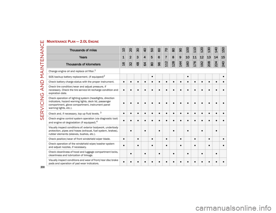
MAINTENANCE PLAN — 2.0L ENGINE
Thousands of miles102030405060708090100110120130140150
Years123456789101112131415
Thousands of kilometers163248648096112128144160176192208224240
Change engine oil and replace oil filter.1
SOS
backup battery replacement. (if equipped)
2 ●●●
Check battery charge status with the proper instrument.
●●●●●●●●●●●●●●●
Check tire condition/wear and adjust pressure, if
necessary. Check the tire service kit recharge condition and
expiration date.
●●●●●●●●●●●●●●●
Check operation of lighting system (headlights, direction
indicators, hazard warning lights, deck lid, passenger
compartment, glove compartment, instrument panel
warning lights, etc.).
●●●●●●●●●●●●●●●
Check and, if necessary, top up fluid levels.
3●●●●●●●●●●●●●●●
Check engine control system operation (via diagnostic tool)
and engine oil degradation (if equipped).
4●●●●●●●●●●●●●●●
Visually inspect conditions of: exterior bodywork, underbody
protection, pipes and hoses (exhaust, fuel system, brakes),
rubber elements (sleeves, bushes, etc.).
●●●●●●●
Check position/wear of front windshield wiper blade.●●●●●●●●
Check operation of the windshield wiper/washer system
and adjust nozzles, if necessary.
●●●●●●●●
Check cleanliness of hood and luggage compartment locks,
cleanliness and lubrication of linkage.
●●●●●●●
Visually inspect conditions and wear of front/rear disc brake
pads and operation of pad wear indicators.●●●●●●●●●●●●●●●
23_GU_OM_EN_USC_t.book Page 200
Page 203 of 268

201
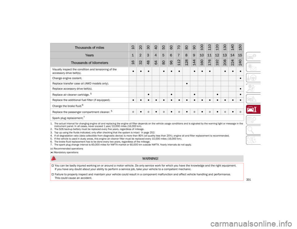
(o) Recommended operations
(●) Mandatory operations
Visually inspect the condition and tensioning of the
accessory drive belt(s).●●●●●●●●●●●●
Change engine coolant.
●
Replace transfer case oil (AWD models only).
●
Replace accessory drive belt(s).●
Replace air cleaner cartridge.
5●●●●●
Replace the additional fuel filter (if equipped).
●●●●●●●●●●●●●●●
Change the brake fluid.
6
Rep
lace the passenger compartment cleaner.
5o●o●o●o●o●o●o●o
Spark plug replacement.
7
1. The actual interval for changing engine oil and replacing the engine oil filter depends on the vehicle usage conditions and is signaled by the warning light or message in the instrument panel. In all cases, never exceed 1 year/10,000 miles (16,000 km).
2. The SOS backup battery must be replaced every five years, regardless of mileage.
3. Top up using the fluids indicated, only after checking that the system is intact
Ú
page 252.
4. If oil degradation ratio (data collectible from diagnostic device) is more than 80% (oil quality less than 20%), engine oil and filter replacement is recommended.
5. If the vehicle is used in dusty areas, this engine air cleaner filter must be replaced every 10,000 miles (16,000 km).
6. The brake fluid replacement has to be done every two years, regardless of the mileage.
7. The spark plug change interval is 60,000 miles for NAFTA market or 60,000 km outside NAFTA. Yearly intervals do not apply.
Thousands of miles102030405060708090100110120130140150
Years123456789101112131415
Thousands of kilometers163248648096112128144160176192208224240
WARNING!
You can be badly injured working on or around a motor vehicle. Do only service work for which you have the knowledge and the right equipment.
If you have any doubt about your ability to perform a service job, take your vehicle to a competent mechanic.
Failure to properly inspect and maintain your vehicle could result in a component malfunction and affect vehicle handling and performance.
This could cause an accident.
23_GU_OM_EN_USC_t.book Page 201