2023 ALFA ROMEO STELVIO break
[x] Cancel search: breakPage 137 of 268
135
(Continued)
(Continued)
TRAILER AND TONGUE WEIGHT
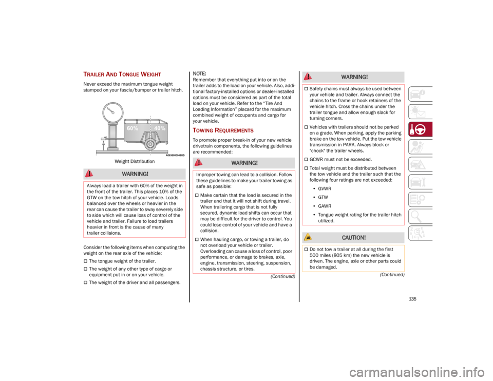
Never exceed the maximum tongue weight
stamped on your fascia/bumper or trailer hitch.
Weight Distribution
Consider the following items when computing the
weight on the rear axle of the vehicle:
The tongue weight of the trailer.
The weight of any other type of cargo or
equipment put in or on your vehicle.
The weight of the driver and all passengers.
NOTE:
Remember that everything put into or on the
trailer adds to the load on your vehicle. Also, addi -
tional factory-installed options or dealer-installed
options must be considered as part of the total
load on your vehicle. Refer to the “Tire And
Loading Information” placard for the maximum
combined weight of occupants and cargo for
your vehicle.
TOWING REQUIREMENTS
To promote proper break-in of your new vehicle
drivetrain components, the following guidelines
are recommended:
WARNING!
Always load a trailer with 60% of the weight in
the front of the trailer. This places 10% of the
GTW on the tow hitch of your vehicle. Loads
balanced over the wheels or heavier in the
rear can cause the trailer to sway severely side
to side which will cause loss of control of the
vehicle and trailer. Failure to load trailers
heavier in front is the cause of many
trailer collisions.
WARNING!
Improper towing can lead to a collision. Follow
these guidelines to make your trailer towing as
safe as possible:
Make certain that the load is secured in the
trailer and that it will not shift during travel.
When trailering cargo that is not fully
secured, dynamic load shifts can occur that
may be difficult for the driver to control. You
could lose control of your vehicle and have a
collision.
When hauling cargo, or towing a trailer, do
not overload your vehicle or trailer.
Overloading can cause a loss of control, poor
performance, or damage to brakes, axle,
engine, transmission, steering, suspension,
chassis structure, or tires.
Safety chains must always be used between
your vehicle and trailer. Always connect the
chains to the frame or hook retainers of the
vehicle hitch. Cross the chains under the
trailer tongue and allow enough slack for
turning corners.
Vehicles with trailers should not be parked
on a grade. When parking, apply the parking
brake on the tow vehicle. Put the tow vehicle
transmission in PARK. Always block or
"chock" the trailer wheels.
GCWR must not be exceeded.
Total weight must be distributed between
the tow vehicle and the trailer such that the
following four ratings are not exceeded:
• GVWR
• GTW
• GAWR
• Tongue weight rating for the trailer hitch
utilized.
CAUTION!
Do not tow a trailer at all during the first
500 miles (805 km) the new vehicle is
driven. The engine, axle or other parts could
be damaged.
WARNING!
23_GU_OM_EN_USC_t.book Page 135
Page 151 of 268

149
When the system does not detect the
presence of hands on the steering wheel from
6 to 15 seconds, the following screen will be
displayed on the instrument cluster display.
A short acoustic signal will sound if hands are
not detected on the steering wheel for 6 to
12 seconds. A continuous signal will sound if
hands are not detected on the steering wheel
for 12 to 15 seconds.Hand Presence On The Steering Wheel Not Detected Display (6 To 15 Seconds)
After 15 seconds with the hands removed from
the steering wheel, the LKA system will be
deactivated and a dedicated message will be
shown on the instrument cluster display.
A short acoustic signal will sound in this case.
In any of the situations where the hands are
removed from the steering wheel for more than
6 seconds, it is necessary to reposition the hands
on the steering wheel. Changing The System Sensitivity
The system's sensitivity can be set through the
radio system. Select the “Driver Assistance”
menu and then select “Comfort”. Sensitivity
“High” or “Low” can be selected.
Rear Cross Path Detection (RCP) System
The Rear Cross Path Detection (RCP) system
assists the driver during reverse maneuvers in
the case of reduced visibility.
When the ABSA system is active, the RCP system
monitors the rear detection areas on both sides
of the vehicle to detect objects moving towards
the sides of the vehicle at a minimum speed
between 0.6 mph and 2 mph (1 km/h and
3km/h) from objects moving at a maximum
speed of 22 mph (35 km/h).
These are generally occurrences that happen in
parking areas.
The system activation is signaled to the driver by
means of a visual and audible warning.
NOTE:
If the sensors are covered by objects or vehicles,
the system may not work as intended.
Changing The System Sensitivity
To change the sensitivity and the strength of the
torque intervention on the steering wheel, refer to
“Settings” of the radio system
Ú
page 259.
DRIVER ATTENTION ASSIST (DAA)
S
YSTEM — IF EQUIPPED
The Driver Attention Assist (DAA) system detects
when the driver is feeling fatigued and warns the
driver to pull over and take a break.
To Activate/Deactivate
The DAA system can be activated and deactivated
through the radio system by selecting the
following in order:
1. “Driver Assistance”
2. “Driver Attention Assist”
WARNING!
The DAA system is an aid for driving and does
not relieve the driver of the responsibility of
driving the vehicle. Always drive alert and get
plenty of rest before driving. If you experience
fatigue while driving, do not wait for the DAA to
intervene with a warning. Choose a safe and
secure location where you can pull over safely
for a break. Only return to the road when you
are in the right physical and mental condition
to prevent endangering yourself and others.
23_GU_OM_EN_USC_t.book Page 149
Page 152 of 268
SAFETY
150
System Intervention
Using information from the front camera, the
system implements two operating logics:
The first operating logic takes the driving style
into account, observing the road and detecting
to what extent the driver can continue driving
with few lane crossing events.
The second operating logic measures the time
spent behind the wheel with the vehicle speed
above 40 mph (60 km/h) and below 110 mph
(180 km/h). If the “Standard” option is
selected, in these conditions, the “Dozy Driver”
message may appear after three hours of
driving. If the “Early” option is selected and
these conditions occur, the “Dozy Driver”
message will be displayed after two hours
of driving.
NOTE:
If the conditions described previously are not
detected continuously during the entire driving
period, the “Dozy Driver” message may be
displayed later than two or three hours. If the
driving style indicates that the driver is unable to
follow the road trajectory and respect the hori-
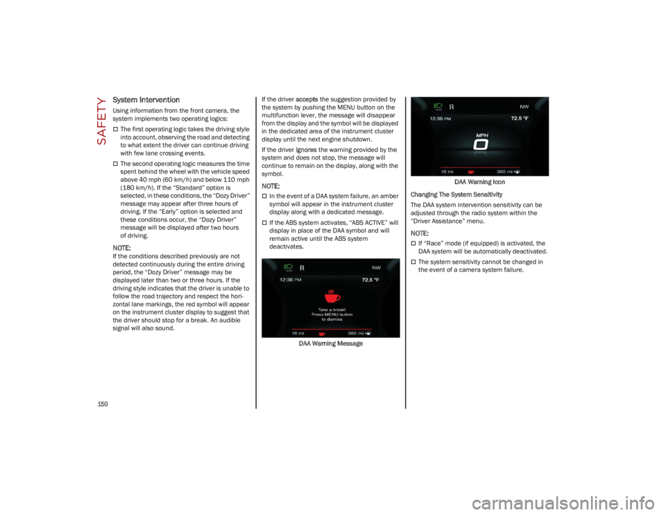
zontal lane markings, the red symbol will appear
on the instrument cluster display to suggest that
the driver should stop for a break. An audible
signal will also sound.If the driver
accepts the suggestion provided by
the system by pushing the MENU button on the
multifunction lever, the message will disappear
from the display and the symbol will be displayed
in the dedicated area of the instrument cluster
display until the next engine shutdown.
If the driver ignores the warning provided by the
system and does not stop, the message will
continue to remain on the display, along with the
symbol.
NOTE:
In the event of a DAA system failure, an amber
symbol will appear in the instrument cluster
display along with a dedicated message.
If the ABS system activates, “ABS ACTIVE” will
display in place of the DAA symbol and will
remain active until the ABS system
deactivates.
DAA Warning Message DAA Warning Icon
Changing The System Sensitivity
The DAA system intervention sensitivity can be
adjusted through the radio system within the
“Driver Assistance” menu.
NOTE:
If “Race” mode (if equipped) is activated, the
DAA system will be automatically deactivated.
The system sensitivity cannot be changed in
the event of a camera system failure.
23_GU_OM_EN_USC_t.book Page 150
Page 198 of 268
IN CASE OF EMERGENCY
196
(Continued)
MANUAL PARK RELEASE
See an authorized dealer to disengage the
manual park release lever.
TOWING A DISABLED
VEHICLE
This section describes procedures for towing a
disabled vehicle using a commercial towing
service.
NOTE:
If your vehicle is equipped with a Anti-Lift Protec-
tion system, you will need to disable the system
prior to towing by pushing the button located on
the overhead console
Ú
page 24.
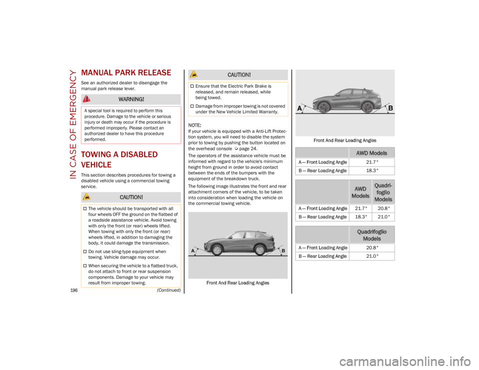
The operators of the assistance vehicle must be
informed with regard to the vehicle's minimum
height from ground in order to avoid contact
between the ends of the bumpers with the
equipment of the breakdown truck.
The following image illustrates the front and rear
attachment corners of the vehicle, to be taken
into consideration when loading the vehicle on
the commercial towing vehicle.
Front And Rear Loading Angles Front And Rear Loading Angles
WARNING!
A special tool is required to perform this
procedure. Damage to the vehicle or serious
injury or death may occur if the procedure is
performed improperly. Please contact an
authorized dealer to have this procedure
performed.
CAUTION!
The vehicle should be transported with all
four wheels OFF the ground on the flatbed of
a roadside assistance vehicle. Avoid towing
with only the front (or rear) wheels lifted.
When towing with only the front (or rear)
wheels lifted, in addition to damaging the
body, it could damage the transmission.
Do not use sling-type equipment when
towing. Vehicle damage may occur.
When securing the vehicle to a flatbed truck,
do not attach to front or rear suspension
components. Damage to your vehicle may
result from improper towing.
Ensure that the Electric Park Brake is
released, and remain released, while
being towed.
Damage from improper towing is not covered
under the New Vehicle Limited Warranty.
CAUTION!
AWD Models
A — Front Loading Angle 21.7°
B — Rear Loading Angle 18.3°
AWD
ModelsQuadri -
foglio
Models
A — Front Loading Angle 21.7° 20.8°
B — Rear Loading Angle 18.3° 21.0°
Quadrifoglio
Models
A — Front Loading Angle 20.8°
B — Rear Loading Angle 21.0°
23_GU_OM_EN_USC_t.book Page 196
Page 199 of 268
197
FOUR-WHEEL DRIVE (AWD) MODELS
It is recommended to tow the vehicle with all
four wheels OFF the ground on the flatbed of a
commercial towing vehicle.
TOW EYES
If the vehicle has been in an accident or has
broken down, a tow eye is provided in the tools
container located inside the luggage
compartment for vehicle towing. Towing is meant
only for short distances on a paved road surface.
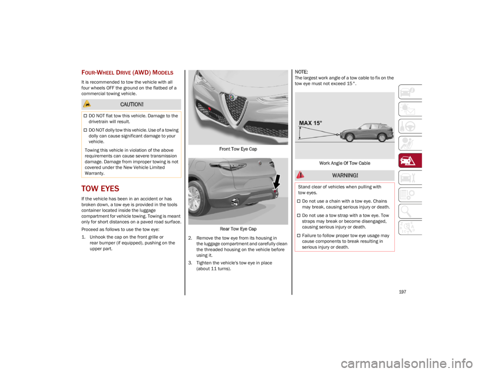
Proceed as follows to use the tow eye:
1. Unhook the cap on the front grille orrear bumper (if equipped), pushing on the
upper part. Front Tow Eye Cap
Rear Tow Eye Cap
2. Remove the tow eye from its housing in the luggage compartment and carefully clean
the threaded housing on the vehicle before
using it.
3. Tighten the vehicle's tow eye in place (about 11 turns).
NOTE:
The largest work angle of a tow cable to fix on the
tow eye must not exceed 15°.
Work Angle Of Tow Cable
CAUTION!
DO NOT flat tow this vehicle. Damage to the
drivetrain will result.
DO NOT dolly tow this vehicle. Use of a towing
dolly can cause significant damage to your
vehicle.
Towing this vehicle in violation of the above
requirements can cause severe transmission
damage. Damage from improper towing is not
covered under the New Vehicle Limited
Warranty.
WARNING!
Stand clear of vehicles when pulling with
tow eyes.
Do not use a chain with a tow eye. Chains
may break, causing serious injury or death.
Do not use a tow strap with a tow eye. Tow
straps may break or become disengaged,
causing serious injury or death.
Failure to follow proper tow eye usage may
cause components to break resulting in
serious injury or death.
23_GU_OM_EN_USC_t.book Page 197
Page 216 of 268

SERVICING AND MAINTENANCE
214
AUTOMATIC TRANSMISSION
Use only a transmission oil with the character-
istics indicated
Ú
page 252.
Special Additives
Do not use any type of additive with the
automatic transmission oil. The automatic
transmission oil is a product designed especially
for this vehicle and its performance may be
compromised through the use of further
additives. Frequency of Oil Changes
In normal vehicle operating conditions, it is not
necessary to change the transmission oil.
REPLACING THE BATTERY
If necessary, replace the battery with another
battery with the same specifications. It is advised
to contact an authorized dealer for replacement.
NOTE:
Each time the 12 Volt battery is reconnected,
cycle the steering wheel all the way to the left.
Then cycle the steering wheel all the way to the
right to allow the steering angle sensor to learn
the steering angle thresholds.
Follow the battery manufacturer's instructions for
maintenance.
NOTE:
It will not be possible to open the liftgate with a
key or by pushing the button in the passenger
compartment when the battery is disconnected. Always position the manual liftgate opening strap
on the liftgate lock before disconnecting the
battery. The procedure is described in the
“Liftgate Emergency Opening”
Ú
page 62.
FUSES
General Information
The fuses protect electrical systems against
excessive current.
When a device does not work, you must check the
electrical circuit inside of the fuse for a break/
melt.
Also, please be aware that using power outlets for
extended periods of time with the engine off may
result in vehicle battery discharge.
Blade Fuses
To avoid contamination from foreign matter
or moisture, use only new brake fluid or fluid
that has been in a tightly closed container.
Keep the master cylinder reservoir cap
secured at all times. Brake fluid in an open
container absorbs moisture from the air
resulting in a lower boiling point. This may
cause it to boil unexpectedly during hard or
prolonged braking, resulting in sudden brake
failure. This could result in a collision.
Overfilling the brake fluid reservoir can result
in spilling brake fluid on hot engine parts,
causing the brake fluid to catch fire. Brake
fluid can also damage painted and vinyl
surfaces, care should be taken to avoid its
contact with these surfaces.
Do not allow petroleum-based fluid to
contaminate the brake fluid. Brake seal
components could be damaged, causing
partial or complete brake failure. This could
result in a collision.
WARNING! CAUTION!
Do not use chemical flushes in your
transmission as the chemicals can damage your
transmission components. Such damage is not
covered by the New Vehicle Limited Warranty.
CAUTION!
If a transmission fluid leak occurs, visit an
authorized dealer immediately. Severe
transmission damage may occur. An
authorized dealer has the proper tools to
adjust the fluid level accurately.
1 — Electrical Circuit
2 — Blade Fuse With Good Electrical Circuit
3 — Blade Fuse With Bad Electrical Circuit
23_GU_OM_EN_USC_t.book Page 214
Page 217 of 268

215
J-CASE Fuse
Fuse Extracting Pliers
To replace a fuse, use the pliers hooked to the
fuse box.
Fuse Box Grab the pliers from the upper tabs, press them,
and extract the pliers pulling upwards.
The pliers have two different ends, both of which
are specifically designed to remove the different
types of fuses present in the vehicle:
Fuse Extracting Pliers
After use, return the pliers to their proper position
using the following procedures:
Grasp the pliers from the upper tabs and insert
them into their housing.
Push downward on the pliers into their housing
until they click into place.
1 — Electrical Circuit
2 — Case Fuse With Good Electrical Circuit
3 — Case Fuse With Bad Electrical Circuit
1 — MINI fuse
2 — J-CASE fuse
WARNING!
When replacing a blown fuse, always use an
appropriate replacement fuse with the same
amp rating as the original fuse. Never
replace a fuse with another fuse of higher
amp rating. Never replace a blown fuse with
metal wires or any other material. Do not
place a fuse inside a circuit breaker cavity or
vice versa. Failure to use proper fuses may
result in serious personal injury, fire and/or
property damage.
Before replacing a fuse, make sure that the
ignition is off and that all the other services
are switched off and/or disengaged.
If the replaced fuse blows again, contact an
authorized dealer.
If a general protection fuse for safety
systems (air bag system, braking system),
power unit systems (engine system,
transmission system) or steering system
blows, contact an authorized dealer.
23_GU_OM_EN_USC_t.book Page 215
Page 239 of 268

237
TIRE ROTATION RECOMMENDATIONS
Tires on the front and rear axles of vehicles
operate at different loads and perform different
steering, driving, and braking functions. For these
reasons, they wear at unequal rates. These
effects can be reduced by timely rotation of tires.
Rotation will increase tread life, maintain traction
levels and contribute to a smooth, quiet ride.
To resolve this problem, tires should be rotated at
each service interval (approximately every
10,000 miles [16,000 km]). More frequent
rotation is permissible if desired. The reasons for
any rapid or unusual wear should be corrected
prior to rotation being performed.
Tire Rotations Not Recommended — If Equipped
Due to different size tires and wheels on front and
rear axles, tire rotation is not possible for:
2.0L Engine equipped with a different front and
rear tire size.
Tire rotation contributes to the preservation of the
grip and traction performance on wet, muddy or
snowy roads, guaranteeing optimal drivability of
the vehicle.
In the case of irregular wear of the tires identify
the cause and correct it as soon as possible, by
contacting an authorized dealer.The rotational direction of the tire must be taken
into consideration when rotating the tires. The
recommended rotation pattern for directional
tires is shown in the following diagram.
Tire Rotation
It is recommended to avoid situations with a large
difference in wear between the front and rear
tires and to strictly use Winter tires of the sizes
given on the tire placard.
The AWD system and the original tires are
developed together to ensure the vehicle’s best
performance. When changing the tires, it is
recommended to us the same “AR” marked tires,
to maintain the same level of performance and
component life.
CAUTION!
To avoid damage to your vehicle or tires,
observe the following precautions:
Because of restricted traction device
clearance between tires and other
suspension components, it is important that
only traction devices in good condition are
used. Broken devices can cause serious
damage. Stop the vehicle immediately if
noise occurs that could indicate device
breakage. Remove the damaged parts of
the device before further use.
Install device as tightly as possible and then
retighten after driving about ½ mile (0.8 km).
Do not exceed 30 mph (48 km/h).
Drive cautiously and avoid severe turns and
large bumps, especially with a loaded
vehicle.
Do not drive for a prolonged period on
dry pavement.
Observe the traction device manufacturer’s
instructions on the method of installation,
operating speed, and conditions for use.
Always use the suggested operating speed of
the device manufacturer’s if it is less than
30 mph (48 km/h).
Do not use traction devices on a compact
spare tire.
CAUTION!
Damage to the vehicle may occur if different
front and rear tire sizes are rotated
23_GU_OM_EN_USC_t.book Page 237