2023 ALFA ROMEO GIULIA fuel type
[x] Cancel search: fuel typePage 14 of 248

12
ENGINE COMPARTMENT....................... 187
Checking Levels — 2.0L Engine .......... 187
Checking Levels — 2.9L Engine .........188
Engine Oil ............................................. 188
Engine Coolant ..................................... 189
Washer Fluid For Windshield/
Headlights ............................................ 189 Brake Fluid ...........................................190
Automatic Transmission Activation
System Oil ............................................ 190 Useful Advice For Extending The Life
Of Your Battery ..................................... 190 Battery ..................................................190
Pressure Washing ................................ 191
BATTERY RECHARGING......................... 191
Important Notes ...................................191
VEHICLE MAINTENANCE ....................... 192
Engine Oil ............................................. 192
Engine Oil Filter ....................................192
Engine Air Cleaner ............................... 192
Air Conditioning System
Maintenance ........................................192 Lubricating Moving Parts Of The
Bodywork ..............................................193 Windshield Wiper .................................193
Exhaust System ...................................194
Engine Cooling System ........................ 195
Braking System ....................................196
Automatic Transmission ......................196
Replacing The Battery ......................... 196
Fuses ................................................... 197
Bulb Replacement ............................... 202
TIRES ..................................................... 206
Tire Safety Information ....................... 206
Tires — General Information .............. 212
Spare Tires — If Equipped .................. 216
Wheel And Wheel Trim Care ............... 217
Tire Types ............................................. 217
Snow Traction Devices ........................ 218
Tire Rotation Recommendations........ 219
DEPARTMENT OF TRANSPORTATION
UNIFORM TIRE QUALITY GRADES ........ 219
Treadwear ............................................ 219
Traction Grades ................................... 220
Temperature Grades ........................... 220
STORING THE VEHICLE ......................... 220
BODYWORK ............................................ 221
Protection Against Atmospheric
Agents .................................................. 221 Corrosion Warranty.............................. 221
Preserving The Bodywork.................... 221
INTERIORS.............................................. 222
Seats And Fabric Parts........................ 222
Leather Seats ...................................... 222
Plastic And Coated Parts .................... 223
Alcantara Parts — If Equipped ............ 223
Genuine Leather Surfaces —
If Equipped ........................................... 223 Carbon Fiber Parts .............................. 223
TECHNICAL SPECIFICATIONS
VEHICLE IDENTIFICATION NUMBER
(VIN) ....................................................... 224
Vehicle Identification Number (VIN)
Plate ..................................................... 224
ENGINE .................................................. 224
POWER SUPPLY ..................................... 225 TRANSMISSION ..................................... 225BRAKES.................................................. 226
SUSPENSION ......................................... 226
STEERING SYSTEM ............................... 226DIMENSIONS — 2.0L ENGINE ............... 227
DIMENSIONS — 2.9L Engine ................ 228
WEIGHTS — 2.0L ENGINE ..................... 229
WEIGHTS — 2.9L ENGINE ..................... 229
FUEL REQUIREMENTS .......................... 230
Reformulated Gasoline....................... 230
Gasoline/Oxygenate Blends ............... 230
CNG And LP Fuel System
Modifications ....................................... 230 Methylcyclopentadienyl Manganese
Tricarbonyl (MMT) In Gasoline ........... 230 Materials Added To Fuel ..................... 230
Fuel System Cautions ......................... 231
FLUID CAPACITIES ................................. 231
2.0L Engine ......................................... 231
2.9L V6 Engine .................................... 232
ENGINE FLUIDS AND LUBRICANTS ...... 233
CHASSIS FLUIDS AND LUBRICANTS..... 234 PERFORMANCE — 2.0L ENGINE........... 235PERFORMANCE — 2.9L ENGINE........... 235
23_GA_OM_EN_USC_t.book Page 12
Page 71 of 248

69
Dynamic
Race (If Equipped)
The display graphically shows the values of: ○ engine torque;
○ turbocharger pressure;
○ engine oil pressure (L = low pressure/ H= high pressure).
NOTE:
The engine torque and turbocharger pressure
values vary according to the engine type.
Race Dynamic
Acceleration Gauge
The displayed parameters are related to vehi -
cle stability, the graphs illustrate the trend of
the longitudinal/lateral accelerations (G-me -
ter information), considering gravity accelera -
tion as a reference unit.
Lateral acceleration peaks are also indicated.
11. Driving Mode Display (Alfa DNA System)
12. Distance Traveled (miles/km) display
13. Fuel Consumption
14. Warning Indications Display (e.g. danger of ice, open doors, ABS operation, etc.)
15. Range
CUSTOMER PROGRAMMABLE SETTINGS
Multiple settings can be programmed by the user
using the radio. This section describes only the
basic settings:
Units & Language
Clock & Date
Cluster
To access the settings list in the radio, proceed as
follows:
Press the Home button to access the main
menu.
Select Settings from the main menu using the
Rotary Knob or by pressing Settings on the
touchscreen.
Rotary Knob
1 — ON/OFF Control And Volume Knob
2 — OPTION Button
3 — Rotary Pad
4 — Home Button
23_GA_OM_EN_USC_t.book Page 69
Page 75 of 248

73
Tire Pressure Low Warning Light
The indicator light will illuminate to
indicate that the tire pressure is lower
than the recommended value and/or
that slow pressure loss is occurring. In
these cases, optimal tire duration and fuel
consumption may not be guaranteed.
In any situation in which the message on the
display is “See Manual”
Ú
page 142.
Tire Pressure Monitoring System (TPMS)
Warning Light
The warning light switches on and a
message is displayed to indicate that
the tire pressure is lower than the
recommended value and/or that slow
pressure loss is occurring. In these cases, optimal
tire duration and fuel consumption may not be
guaranteed.
Should one or more tires be in the condition
mentioned previously, the display will show the
indications corresponding to each tire.
Each tire, including the spare (if provided), should
be checked monthly when cold and inflated to the
inflation pressure recommended by the vehicle
manufacturer on the vehicle placard or tire inflation pressure label. If your vehicle has tires of
a different size than the size indicated on the
vehicle placard or tire inflation pressure label, you
should determine the proper tire inflation
pressure for those tires.
As an added safety feature, your vehicle has been
equipped with a TPMS that illuminates a low tire
pressure telltale when one or more of your tires is
significantly underinflated. Accordingly, when the
low tire pressure telltale illuminates, you should
stop and check your tires as soon as possible,
and inflate them to the proper pressure. Driving
on a significantly underinflated tire causes the
tire to overheat and can lead to tire failure.
Underinflation also reduces fuel efficiency and
tire tread life, and may affect the vehicle’s
handling and stopping ability.
Please note that the TPMS is not a substitute for
proper tire maintenance, and it is the driver’s
responsibility to maintain correct tire pressure,
even if underinflation has not reached the level to
trigger illumination of the TPMS low tire pressure
telltale.
Your vehicle has also been equipped with a TPMS
malfunction indicator to indicate when the
system is not operating properly. The TPMS
malfunction indicator is combined with the low
tire pressure telltale. When the system detects a
malfunction, the telltale will flash for approxi
-
mately one minute and then remain continuously
illuminated. This sequence will continue upon
subsequent vehicle start-ups as long as the
malfunction exists. When the malfunction
indicator is illuminated, the system may not be
able to detect or signal low tire pressure as
intended. TPMS malfunctions may occur for a
variety of reasons, including the installation of
replacement or alternate tires or wheels on the vehicle that prevent the TPMS from functioning
properly. Always check the TPMS malfunction
telltale after replacing one or more tires or wheels
on your vehicle to ensure that the replacement or
alternate tires and wheels allow the TPMS to
continue to function properly.
Rear Fog Lights
The indicator illuminates when the rear
fog light is activated.
Engine Check/Malfunction Indicator Light
(MIL)
In normal conditions, when the ignition
is cycled to ON, the indicator light
illuminates, but it should turn off as
soon as the engine is started.
CAUTION!
Do not continue driving with one or more flat
tires as handling may be compromised. Stop
the vehicle, avoiding sharp braking and
steering. If a tire puncture occurs, repair
immediately using the dedicated tire repair kit
and contact an authorized dealer as soon as
possible.
WARNING!
The TPMS has been optimized for the original
equipment tires and wheels. TPMS pressures
and warning have been established for the tire
size equipped on your vehicle. Undesirable
system operation or sensor damage may
result when using replacement equipment
that is not of the same size, type, and/or style.
Aftermarket wheels can cause sensor
damage. Using aftermarket tire sealants may
cause the Tire Pressure Monitoring System
(TPMS) sensor to become inoperable. After
using an aftermarket tire sealant it is
recommended that you take your vehicle to an
authorized dealership to have your sensor
function checked.
23_GA_OM_EN_USC_t.book Page 73
Page 83 of 248

81
STARTING THE ENGINE
Before starting the engine, be sure to adjust the
seat, the interior rearview mirror, the door
mirrors, and fasten the seat belt correctly.
Never press the accelerator pedal before starting
the engine.
If necessary, messages indicating the starting
procedure will be shown in the display.
STARTING PROCEDURE
Proceed as follows:
1. Apply the Electric Park Brake and set the gear selector to PARK (P) or NEUTRAL (N).
2. Fully press the brake pedal without touching the accelerator.
3. Briefly push the ignition button.
4. If the engine doesn't start within a few seconds, you need to repeat the procedure. If
the problem persists, contact an authorized
dealer.
REMOTE STARTING SYSTEM
This system uses the key fob to start the engine
conveniently from outside the vehicle while still
maintaining security. The system has a range of
at least 300 feet (91 meters).
The remote starting system also activates the
climate control, the heated seats (if equipped),
and the heated steering wheel (if equipped),
depending on temperatures outside and inside of
the vehicle.
NOTE:
Obstructions between the vehicle and key fob
may reduce this range.
How to use Remote Start
All of the following conditions must be met before
the engine will remote start:
Gear selector in PARK (P).
Doors closed.
Hood closed.
Trunk closed.
Hazard switch off.
Brake switch inactive (brake pedal not
pressed).
WARNING!
When leaving the vehicle, always remove the
key fob from the vehicle and lock your
vehicle.
Never leave children alone in a vehicle, or
with access to an unlocked vehicle.
Allowing children to be in a vehicle
unattended is dangerous for a number of
reasons. A child or others could be seriously
or fatally injured. Children should be warned
not to touch the parking brake, brake pedal
or the transmission gear selector.
Do not leave the key fob in or near the
vehicle, or in a location accessible to
children. A child could operate power
windows, other controls, or move the vehicle.
Do not leave children or animals inside
parked vehicles in hot weather. Interior heat
buildup may cause serious injury or death.
WARNING!
Never pour fuel or other flammable liquid
into the throttle body air inlet opening in an
attempt to start the vehicle. This could result
in flash fire causing serious personal injury.
Do not attempt to push or tow your vehicle to
get it started. Vehicles equipped with an
automatic transmission cannot be started
this way. Unburned fuel could enter the
catalytic converter and once the engine has
started, ignite and damage the converter and
vehicle.
If the vehicle has a discharged battery,
booster cables may be used to obtain a start
from a booster battery or the battery in
another vehicle
Ú
page 177. This type of
start can be dangerous if done improperly.
CAUTION!
To prevent damage to the starter, do not
continuously crank the engine for more than
25 seconds at a time. Wait 60 seconds before
trying again.
23_GA_OM_EN_USC_t.book Page 81
Page 84 of 248

STARTING AND OPERATING
82
Battery at an acceptable charge level.
PANIC button not pushed.
System not disabled from previous remote
start event.
Vehicle alarm system indicator flashing.
Ignition in the OFF position.
Fuel level meets minimum requirement.
Remote Start Comfort Systems — If Equipped
When Remote Start is activated, the heated
steering wheel and driver heated seat features
will automatically turn on in cold weather.
These features will stay on through the duration
of remote start until the ignition is placed in the
ON/RUN position.
Remote Start Windshield Wiper De–Icer
Activation — If Equipped
When remote start is active and the outside
ambient temperature is less than 39°F (4°C),
the Windshield Wiper De-Icer will be enabled.
Exiting remote start will resume previous
operation, except if the Windshield Wiper De-Icer
is active.
The Windshield Wiper De-Icer timer and
operation will continue.
COLD WEATHER OPERATION
To prevent possible engine damage while starting
at low temperatures, this vehicle will inhibit
engine cranking when the ambient temperature
is less than –22°F (–30°C) and the oil
temperature sensor reading indicates an engine
block heater has not been used. An
externally-powered electric engine block heater is
available as optional equipment or from an
authorized dealer. The message “Plug In Engine Heater” will be
displayed in the instrument cluster when the
ambient temperature is below 5°F (–15°C) at
the time the engine is shut off as a reminder to
avoid possible crank delays at the next cold start.
EXTENDED PARK STARTING
If the vehicle has not been started or driven for at
least 30 days, see the following instructions:
To start the engine, proceed as follows:
1. Install a battery charger or jumper cables to
the battery to ensure a full battery charge
during the crank cycle
Ú
page 177.
2. Briefly push the ignition button.
3. If the engine does not start, wait five seconds and let the starter cool down and then repeat
the starting procedure.
4. If the engine does not start after eight attempts, let the starter cool down for at least
10 seconds, and then repeat the starting
procedure. If the problem persists, contact
an authorized dealer.
IF ENGINE FAILS TO START
Starting the Engine with Key Fob Battery Run
Down or Drained
If the ignition does not respond when the button
is pushed, the key fob battery might be run down or drained. Therefore, the system does not detect
the presence of the key fob in the vehicle, and will
display a dedicated message.
For more information on starting with a
discharged key fob battery
Ú
page 22.
CAUTION!
Use of the recommended oil and adhering to
the prescribed oil change intervals is
important to prevent engine damage and
ensure satisfactory starting in cold conditions.
WARNING!
Never pour fuel or other flammable liquid
into the throttle body air inlet opening in an
attempt to start the vehicle. This could result
in flash fire causing serious personal injury.
Do not attempt to push or tow your vehicle to
get it started. Vehicles equipped with an
automatic transmission cannot be started
this way. Unburned fuel could enter the
catalytic converter and once the engine has
started, ignite and damage the converter
and vehicle.
If the vehicle has a discharged battery,
booster cables may be used to obtain a start
from a booster battery or the battery in
another vehicle
Ú
page 177. This type of
start can be dangerous if done improperly.
CAUTION!
To prevent damage to the starter, do not
continuously crank the engine for more than
25 seconds at a time. Wait 60 seconds before
trying again.
23_GA_OM_EN_USC_t.book Page 82
Page 96 of 248

STARTING AND OPERATING
94
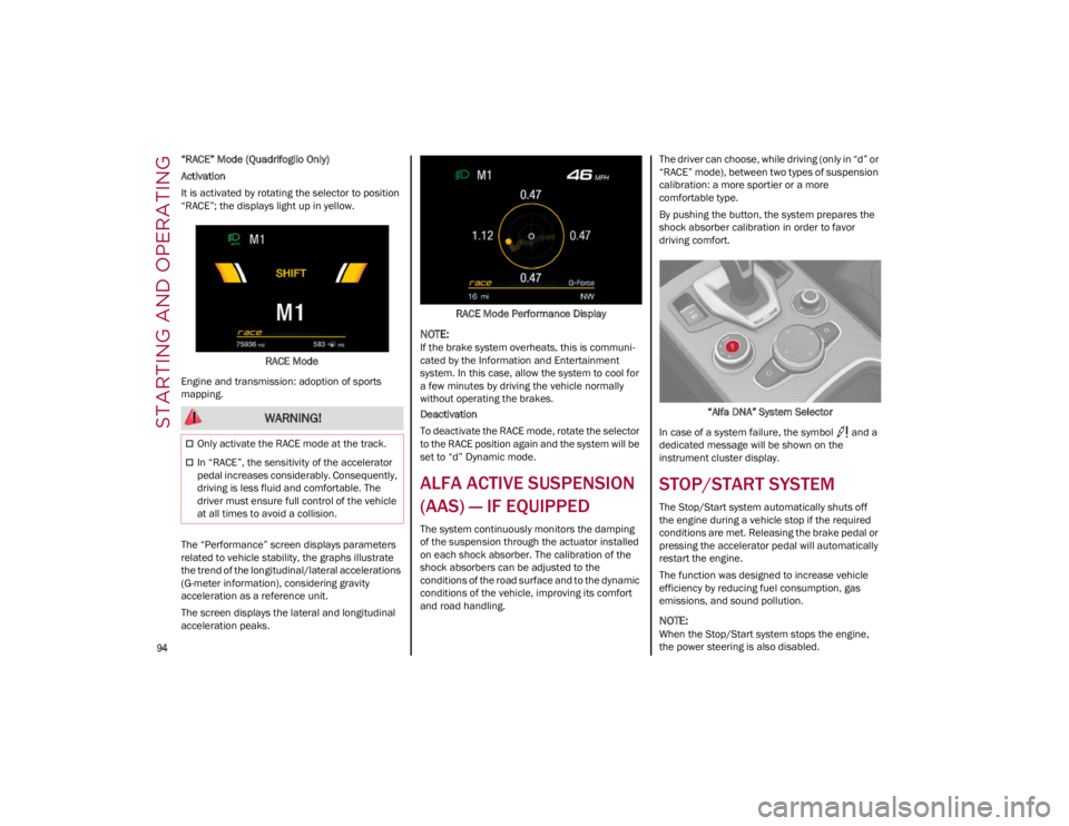
“RACE” Mode (Quadrifoglio Only)
Activation
It is activated by rotating the selector to position
“RACE”; the displays light up in yellow.RACE Mode
Engine and transmission: adoption of sports
mapping.
The “Performance” screen displays parameters
related to vehicle stability, the graphs illustrate
the trend of the longitudinal/lateral accelerations
(G-meter information), considering gravity
acceleration as a reference unit.
The screen displays the lateral and longitudinal
acceleration peaks. RACE Mode Performance Display
NOTE:
If the brake system overheats, this is communi
-
cated by the Information and Entertainment
system. In this case, allow the system to cool for
a few minutes by driving the vehicle normally
without operating the brakes.
Deactivation
To deactivate the RACE mode, rotate the selector
to the RACE position again and the system will be
set to “d” Dynamic mode.
ALFA ACTIVE SUSPENSION
(AAS) — IF EQUIPPED
The system continuously monitors the damping
of the suspension through the actuator installed
on each shock absorber. The calibration of the
shock absorbers can be adjusted to the
conditions of the road surface and to the dynamic
conditions of the vehicle, improving its comfort
and road handling. The driver can choose, while driving (only in “d” or
“RACE” mode), between two types of suspension
calibration: a more sportier or a more
comfortable type.
By pushing the button, the system prepares the
shock absorber calibration in order to favor
driving comfort.
“Alfa DNA” System Selector
In case of a system failure, the symbol and a
dedicated message will be shown on the
instrument cluster display.
STOP/START SYSTEM
The Stop/Start system automatically shuts off
the engine during a vehicle stop if the required
conditions are met. Releasing the brake pedal or
pressing the accelerator pedal will automatically
restart the engine.
The function was designed to increase vehicle
efficiency by reducing fuel consumption, gas
emissions, and sound pollution.
NOTE:
When the Stop/Start system stops the engine,
the power steering is also disabled.
WARNING!
Only activate the RACE mode at the track.
In “RACE”, the sensitivity of the accelerator
pedal increases considerably. Consequently,
driving is less fluid and comfortable. The
driver must ensure full control of the vehicle
at all times to avoid a collision.
23_GA_OM_EN_USC_t.book Page 94
Page 126 of 248

STARTING AND OPERATING
124
(Continued)
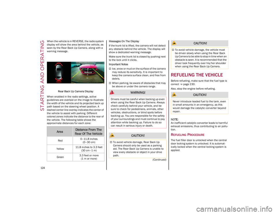
When the vehicle is in REVERSE, the radio system
display will show the area behind the vehicle, as
seen by the Rear Back Up Camera, along with a
warning message.
Rear Back Up Camera Display
When enabled in the radio settings, active
guidelines are overlaid on the image to illustrate
the width of the vehicle and its projected back up
path based on the steering wheel position. A
dashed center line overlay indicates the center of
the vehicle to assist with parking. Different
colored zones indicate the distance to the rear of
the vehicle. The following table shows the
approximate distances for each zone: Messages On The Display
If the trunk lid is lifted, the camera will not detect
any obstacle behind the vehicle. The display will
show a dedicated warning message.
Make sure the trunk lid is closed by pushing next
to the lock until it clicks.
Important Notes
Ice, snow or mud on the surface of the camera
may reduce its sensitivity. It is important to
keep the camera surface clean, and free from
debris.
When parking, be aware of obstacles that may
be above or under the camera range.
REFUELING THE VEHICLE
Before refueling, make sure that the fuel type is
correct
Ú
page 230.
Also, stop the engine before refueling.
NOTE:
An inefficient catalytic converter leads to harmful
exhaust emissions, thus contributing to air pollu -
tion.
REFUELING PROCEDURE
The fuel filler door is unlocked when the central
door locking system is unlocked. It is automat -
ically locked when the central locking system is
applied.
AreaDistance From The
Rear Of The Vehicle
Red 0–11.8 inches
(0–30 cm)
Yellow 11.8 inches to 3.3 feet
(30 cm–1 m)
Green 3.3 feet or more
(1 m or more)
WARNING!
Drivers must be careful when backing up even
when using the Rear Back Up Camera. Always
check carefully behind your vehicle, and be
sure to check for pedestrians, animals, other
vehicles, obstructions, or blind spots before
backing up. You are responsible for the safety
of your surroundings and must continue to pay
attention while backing up. Failure to do so
can result in serious injury or death.
CAUTION!
To avoid vehicle damage, Rear Back Up
Camera should only be used as a parking
aid. The Rear Back Up Camera is unable to
view every obstacle or object in your drive
path.
To avoid vehicle damage, the vehicle must
be driven slowly when using the Rear Back
Up Camera to be able to stop in time when an
obstacle is seen. It is recommended that the
driver look frequently over his/her shoulder
when using the Rear Back Up Camera.
CAUTION!
Never introduce leaded fuel to the tank, even
in small amounts in an emergency, as this
would damage the catalytic converter beyond
repair.
CAUTION!
23_GA_OM_EN_USC_t.book Page 124
Page 127 of 248

125
Opening The Fuel Filler Door
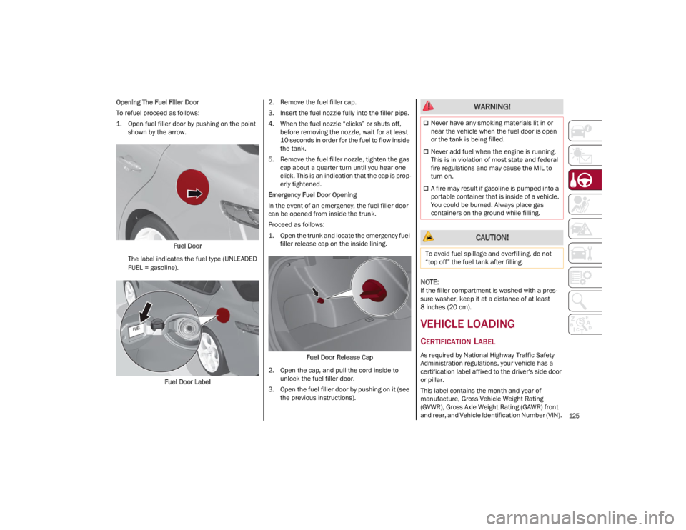
To refuel proceed as follows:
1. Open fuel filler door by pushing on the point shown by the arrow.
Fuel Door
The label indicates the fuel type (UNLEADED
FUEL = gasoline).
Fuel Door Label 2. Remove the fuel filler cap.
3. Insert the fuel nozzle fully into the filler pipe.
4. When the fuel nozzle “clicks” or shuts off,
before removing the nozzle, wait for at least
10 seconds in order for the fuel to flow inside
the tank.
5. Remove the fuel filler nozzle, tighten the gas cap about a quarter turn until you hear one
click. This is an indication that the cap is prop -
erly tightened.
Emergency Fuel Door Opening
In the event of an emergency, the fuel filler door
can be opened from inside the trunk.
Proceed as follows:
1. Open the trunk and locate the emergency fuel filler release cap on the inside lining.
Fuel Door Release Cap
2. Open the cap, and pull the cord inside to unlock the fuel filler door.
3. Open the fuel filler door by pushing on it (see the previous instructions).
NOTE:
If the filler compartment is washed with a pres -
sure washer, keep it at a distance of at least
8 inches (20 cm).
VEHICLE LOADING
CERTIFICATION LABEL
As required by National Highway Traffic Safety
Administration regulations, your vehicle has a
certification label affixed to the driver's side door
or pillar.
This label contains the month and year of
manufacture, Gross Vehicle Weight Rating
(GVWR), Gross Axle Weight Rating (GAWR) front
and rear, and Vehicle Identification Number (VIN).
WARNING!
Never have any smoking materials lit in or
near the vehicle when the fuel door is open
or the tank is being filled.
Never add fuel when the engine is running.
This is in violation of most state and federal
fire regulations and may cause the MIL to
turn on.
A fire may result if gasoline is pumped into a
portable container that is inside of a vehicle.
You could be burned. Always place gas
containers on the ground while filling.
CAUTION!
To avoid fuel spillage and overfilling, do not
“top off” the fuel tank after filling.
23_GA_OM_EN_USC_t.book Page 125