2023 ALFA ROMEO GIULIA fuel consumption
[x] Cancel search: fuel consumptionPage 69 of 248
67
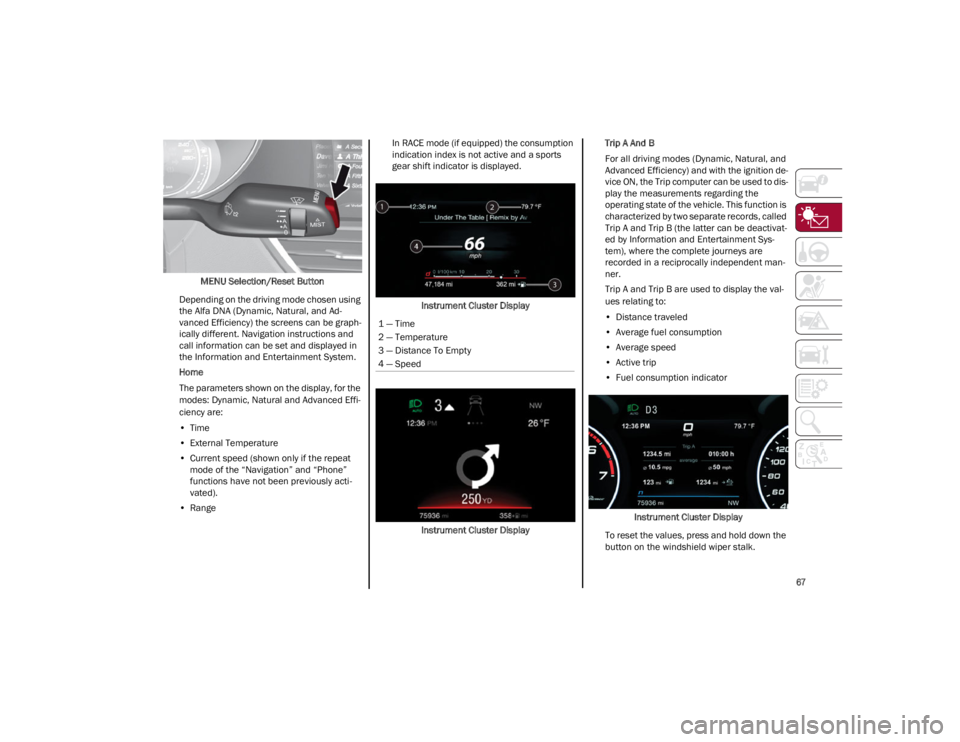
MENU Selection/Reset Button
Depending on the driving mode chosen using
the Alfa DNA (Dynamic, Natural, and Ad -
vanced Efficiency) the screens can be graph -
ically different. Navigation instructions and
call information can be set and displayed in
the Information and Entertainment System.
Home
The parameters shown on the display, for the
modes: Dynamic, Natural and Advanced Effi -
ciency are:
• Time
• External Temperature
• Current speed (shown only if the repeat
mode of the “Navigation” and “Phone”
functions have not been previously acti-vated).
• Range In RACE mode (if equipped) the consumption
indication index is not active and a sports
gear shift indicator is displayed.
Instrument Cluster Display
Instrument Cluster Display Trip A And B
For all driving modes (Dynamic, Natural, and
Advanced Efficiency) and with the ignition de
-
vice ON, the Trip computer can be used to dis -
play the measurements regarding the
operating state of the vehicle. This function is
characterized by two separate records, called
Trip A and Trip B (the latter can be deactivat -
ed by Information and Entertainment Sys -
tem), where the complete journeys are
recorded in a reciprocally independent man -
ner.
Trip A and Trip B are used to display the val -
ues relating to:
• Distance traveled
• Average fuel consumption
• Average speed
• Active trip
• Fuel consumption indicator
Instrument Cluster Display
To reset the values, press and hold down the
button on the windshield wiper stalk.
1 — Time
2 — Temperature
3 — Distance To Empty
4 — Speed
23_GA_OM_EN_USC_t.book Page 67
Page 70 of 248

GETTING TO KNOW YOUR INSTRUMENT PANEL
68
Performance
The displayed parameters differ according to
the active mode. The modes which can be se-
lected using the Alfa DNA system are:
Natural
Efficiency Consumption Graph
The screen graphically reproduces some pa -
rameters closely linked to the efficiency of
the driving style, with a view to limiting con -
sumption. Advanced Efficiency
Dynamic Driving Style
The three central icons, on the screen, indi -
cate the effectiveness of the driving style
linked to the parameters of: acceleration, de -
celeration and gear shift with a view to reduc -
ing fuel consumption.
The graphic bar below the icons shows cur -
rent consumption and the green line rep -
resents the optimal area. The globe lights up
gradually according to lower consumption.
Alternative Performance
The displayed parameters vary depending on
the active mode. The modes can be selected
through the Alfa DNA™ system and are as fol -
lows: Natural and Advanced Efficiency
The display graphically shows the values of:
○ instantaneous consumption
○ average fuel consumption (based on “Trip A”);
Below a certain speed value, when the accel -
erator pedal is not pressed or in the event of
failure, dashes are displayed in place of the
consumption value ("– –. –").
Natural and Advanced Efficiency
Dynamic
The display graphically shows the values of: ○ accelerator pedal position (expressed in percentage);
○ brake pedal position (expressed in percentage);
○ engine coolant temperature (H = hot/ C = cold).
1 — Acceleration
2 — Deceleration
3 — Gear Shifts
23_GA_OM_EN_USC_t.book Page 68
Page 71 of 248

69
Dynamic
Race (If Equipped)
The display graphically shows the values of: ○ engine torque;
○ turbocharger pressure;
○ engine oil pressure (L = low pressure/ H= high pressure).
NOTE:
The engine torque and turbocharger pressure
values vary according to the engine type.
Race Dynamic
Acceleration Gauge
The displayed parameters are related to vehi -
cle stability, the graphs illustrate the trend of
the longitudinal/lateral accelerations (G-me -
ter information), considering gravity accelera -
tion as a reference unit.
Lateral acceleration peaks are also indicated.
11. Driving Mode Display (Alfa DNA System)
12. Distance Traveled (miles/km) display
13. Fuel Consumption
14. Warning Indications Display (e.g. danger of ice, open doors, ABS operation, etc.)
15. Range
CUSTOMER PROGRAMMABLE SETTINGS
Multiple settings can be programmed by the user
using the radio. This section describes only the
basic settings:
Units & Language
Clock & Date
Cluster
To access the settings list in the radio, proceed as
follows:
Press the Home button to access the main
menu.
Select Settings from the main menu using the
Rotary Knob or by pressing Settings on the
touchscreen.
Rotary Knob
1 — ON/OFF Control And Volume Knob
2 — OPTION Button
3 — Rotary Pad
4 — Home Button
23_GA_OM_EN_USC_t.book Page 69
Page 75 of 248

73
Tire Pressure Low Warning Light
The indicator light will illuminate to
indicate that the tire pressure is lower
than the recommended value and/or
that slow pressure loss is occurring. In
these cases, optimal tire duration and fuel
consumption may not be guaranteed.
In any situation in which the message on the
display is “See Manual”
Ú
page 142.
Tire Pressure Monitoring System (TPMS)
Warning Light
The warning light switches on and a
message is displayed to indicate that
the tire pressure is lower than the
recommended value and/or that slow
pressure loss is occurring. In these cases, optimal
tire duration and fuel consumption may not be
guaranteed.
Should one or more tires be in the condition
mentioned previously, the display will show the
indications corresponding to each tire.
Each tire, including the spare (if provided), should
be checked monthly when cold and inflated to the
inflation pressure recommended by the vehicle
manufacturer on the vehicle placard or tire inflation pressure label. If your vehicle has tires of
a different size than the size indicated on the
vehicle placard or tire inflation pressure label, you
should determine the proper tire inflation
pressure for those tires.
As an added safety feature, your vehicle has been
equipped with a TPMS that illuminates a low tire
pressure telltale when one or more of your tires is
significantly underinflated. Accordingly, when the
low tire pressure telltale illuminates, you should
stop and check your tires as soon as possible,
and inflate them to the proper pressure. Driving
on a significantly underinflated tire causes the
tire to overheat and can lead to tire failure.
Underinflation also reduces fuel efficiency and
tire tread life, and may affect the vehicle’s
handling and stopping ability.
Please note that the TPMS is not a substitute for
proper tire maintenance, and it is the driver’s
responsibility to maintain correct tire pressure,
even if underinflation has not reached the level to
trigger illumination of the TPMS low tire pressure
telltale.
Your vehicle has also been equipped with a TPMS
malfunction indicator to indicate when the
system is not operating properly. The TPMS
malfunction indicator is combined with the low
tire pressure telltale. When the system detects a
malfunction, the telltale will flash for approxi
-
mately one minute and then remain continuously
illuminated. This sequence will continue upon
subsequent vehicle start-ups as long as the
malfunction exists. When the malfunction
indicator is illuminated, the system may not be
able to detect or signal low tire pressure as
intended. TPMS malfunctions may occur for a
variety of reasons, including the installation of
replacement or alternate tires or wheels on the vehicle that prevent the TPMS from functioning
properly. Always check the TPMS malfunction
telltale after replacing one or more tires or wheels
on your vehicle to ensure that the replacement or
alternate tires and wheels allow the TPMS to
continue to function properly.
Rear Fog Lights
The indicator illuminates when the rear
fog light is activated.
Engine Check/Malfunction Indicator Light
(MIL)
In normal conditions, when the ignition
is cycled to ON, the indicator light
illuminates, but it should turn off as
soon as the engine is started.
CAUTION!
Do not continue driving with one or more flat
tires as handling may be compromised. Stop
the vehicle, avoiding sharp braking and
steering. If a tire puncture occurs, repair
immediately using the dedicated tire repair kit
and contact an authorized dealer as soon as
possible.
WARNING!
The TPMS has been optimized for the original
equipment tires and wheels. TPMS pressures
and warning have been established for the tire
size equipped on your vehicle. Undesirable
system operation or sensor damage may
result when using replacement equipment
that is not of the same size, type, and/or style.
Aftermarket wheels can cause sensor
damage. Using aftermarket tire sealants may
cause the Tire Pressure Monitoring System
(TPMS) sensor to become inoperable. After
using an aftermarket tire sealant it is
recommended that you take your vehicle to an
authorized dealership to have your sensor
function checked.
23_GA_OM_EN_USC_t.book Page 73
Page 86 of 248
STARTING AND OPERATING
84
ENGINE BREAK-IN
RECOMMENDATIONS
ENGINE BREAK-IN
For both engines, use the following engine
break-in recommendations:
NOTE:
A new engine may consume some oil during its
first few thousand miles (kilometers) of opera-
tion. This should be considered a normal part of
the break-in period and not interpreted as an indi -
cation of a problem. Please monitor your oil level
during the break-in period and add oil as
required.
It is recommended for the operator to observe the
following driving behaviors during the new vehicle
break-in period:
0 to 100 miles (0 to 160 km):
Do not allow the engine to operate at idle for
an extended period of time.
Press the accelerator pedal slowly and not
more than halfway to avoid rapid acceleration.
Avoid aggressive braking.
Drive with the engine speed less than
3,500 RPM.
Maintain vehicle speed below 55 mph
(88 km/h) and observe local speed limits. 100 to 300 miles (160 to 483 km):
Press the accelerator pedal slowly and not
more than halfway to avoid rapid acceleration
in lower gears (FIRST to THIRD gears).
Avoid aggressive braking.
Drive with the engine speed less than
5,000 RPM.
Maintain vehicle speed below 70 mph
(112 km/h) and observe local speed limits.
300 to 500 miles (483 to 805 km):
Exercise the full engine RPM range, shifting
manually (paddles or gear shift) at higher RPM
when possible.
Do not perform sustained operation with the
accelerator pedal at wide open throttle.
Maintain vehicle speed below 85 mph
(136 km/h) and observe local speed limits.
For the first 1,500 miles (2,414 km):
Do not participate in track events, sport driving
schools, or similar activities during the first
1,500 miles (2,414 km).
NOTE:
Monitor engine oil with every refueling and add if
necessary. Oil and fuel consumption may be
higher through the first oil change interval.
ELECTRIC PARK BRAKE
(EPB)
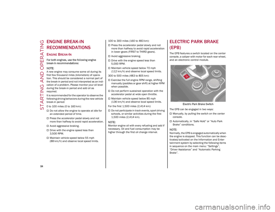
The EPB features a switch located on the center
console, a caliper with motor for each rear wheel,
and an electronic control module.
Electric Park Brake Switch
The EPB can be engaged in two ways:
Manually, by pulling the switch on the center
console.
Automatically, in “Safe Hold” or “Auto Park
Brake” conditions.
NOTE:
Normally, the EPB is engaged automatically when
the engine is stopped. This function can be deac -
tivated/activated on the Information and Enter -
tainment system by selecting the following items
in sequence on the main menu: “Settings”,
“Driver Assistance” and “Automatic Parking
Brake”.
23_GA_OM_EN_USC_t.book Page 84
Page 91 of 248
89
REVERSE (R)
Select this mode only with the vehicle at a
standstill.
NEUTRAL (N)
Use this range when the vehicle is standing for
prolonged periods with the engine running. The
engine may be started in this range. Apply the Electric Park Brake and shift the transmission
into PARK (P) if you must leave the vehicle.
DRIVE (D)
Use this mode in normal driving conditions.
Shifting from DRIVE (D) to PARK (P) or REVERSE
(R) modes must take place only after releasing
the accelerator pedal, with vehicle at a standstill
and brake pedal pressed.
This mode ensures automatic engagement of the
most suitable gears for driving needs and
maximum fuel economy in terms of consumption.
In this position, the transmission shifts the gears
automatically, selecting the most suitable for
forward driving among those available as you go.
This ensures the vehicle's optimal driving charac
-
teristics are provided for all conditions.
AutoStick
In the case of frequent shifting (e.g. for sport
driving, when the vehicle is driven with a heavy
load or on slopes), it is recommended to use the
AutoStick (sequential shifting) mode to select and
keep a lower fixed ratio.
In these conditions, the use of a lower gear
improves vehicle performance, preventing
overheating. It is possible to shift from DRIVE (D) mode to
sequential mode regardless of vehicle speed.
Activation
Starting from DRIVE (D), move the selector to the
left (– and + indication of the trim) to activate the
sequential drive mode. The gear engaged will be
shown on the display.
Shifting is made by moving the gear selector
forwards, towards symbol – or backwards,
towards symbol +.
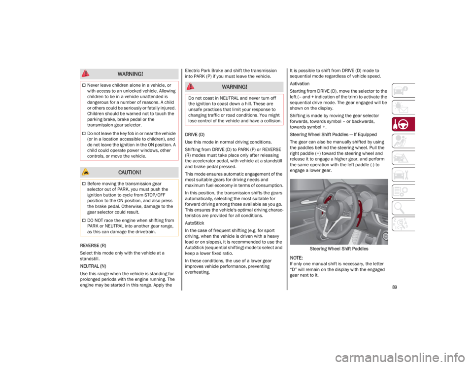
Steering Wheel Shift Paddles — If Equipped
The gear can also be manually shifted by using
the paddles behind the steering wheel. Pull the
right paddle (+) toward the steering wheel and
release it to engage a higher gear, and perform
the same operation with the left paddle (-) to
engage a lower gear.
Steering Wheel Shift Paddles
NOTE:
If only one manual shift is necessary, the letter
“D” will remain on the display with the engaged
gear next to it.
Never leave children alone in a vehicle, or
with access to an unlocked vehicle. Allowing
children to be in a vehicle unattended is
dangerous for a number of reasons. A child
or others could be seriously or fatally injured.
Children should be warned not to touch the
parking brake, brake pedal or the
transmission gear selector.
Do not leave the key fob in or near the vehicle
(or in a location accessible to children), and
do not leave the ignition in the ON position. A
child could operate power windows, other
controls, or move the vehicle.
CAUTION!
Before moving the transmission gear
selector out of PARK, you must push the
ignition button to cycle from STOP/OFF
position to the ON position, and also press
the brake pedal. Otherwise, damage to the
gear selector could result.
DO NOT race the engine when shifting from
PARK or NEUTRAL into another gear range,
as this can damage the drivetrain.
WARNING!
WARNING!
Do not coast in NEUTRAL and never turn off
the ignition to coast down a hill. These are
unsafe practices that limit your response to
changing traffic or road conditions. You might
lose control of the vehicle and have a collision.
23_GA_OM_EN_USC_t.book Page 89
Page 96 of 248
STARTING AND OPERATING
94
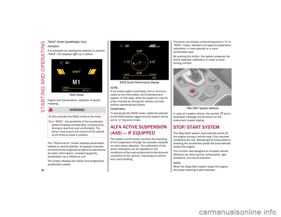
“RACE” Mode (Quadrifoglio Only)
Activation
It is activated by rotating the selector to position
“RACE”; the displays light up in yellow.RACE Mode
Engine and transmission: adoption of sports
mapping.
The “Performance” screen displays parameters
related to vehicle stability, the graphs illustrate
the trend of the longitudinal/lateral accelerations
(G-meter information), considering gravity
acceleration as a reference unit.
The screen displays the lateral and longitudinal
acceleration peaks. RACE Mode Performance Display
NOTE:
If the brake system overheats, this is communi
-
cated by the Information and Entertainment
system. In this case, allow the system to cool for
a few minutes by driving the vehicle normally
without operating the brakes.
Deactivation
To deactivate the RACE mode, rotate the selector
to the RACE position again and the system will be
set to “d” Dynamic mode.
ALFA ACTIVE SUSPENSION
(AAS) — IF EQUIPPED
The system continuously monitors the damping
of the suspension through the actuator installed
on each shock absorber. The calibration of the
shock absorbers can be adjusted to the
conditions of the road surface and to the dynamic
conditions of the vehicle, improving its comfort
and road handling. The driver can choose, while driving (only in “d” or
“RACE” mode), between two types of suspension
calibration: a more sportier or a more
comfortable type.
By pushing the button, the system prepares the
shock absorber calibration in order to favor
driving comfort.
“Alfa DNA” System Selector
In case of a system failure, the symbol and a
dedicated message will be shown on the
instrument cluster display.
STOP/START SYSTEM
The Stop/Start system automatically shuts off
the engine during a vehicle stop if the required
conditions are met. Releasing the brake pedal or
pressing the accelerator pedal will automatically
restart the engine.
The function was designed to increase vehicle
efficiency by reducing fuel consumption, gas
emissions, and sound pollution.
NOTE:
When the Stop/Start system stops the engine,
the power steering is also disabled.
WARNING!
Only activate the RACE mode at the track.
In “RACE”, the sensitivity of the accelerator
pedal increases considerably. Consequently,
driving is less fluid and comfortable. The
driver must ensure full control of the vehicle
at all times to avoid a collision.
23_GA_OM_EN_USC_t.book Page 94
Page 128 of 248
STARTING AND OPERATING
126
A Month-Day-Hour (MDH) number is included on
this label and indicates the Month, Day and Hour
of manufacture. The bar code that appears on
the bottom of the label is your VIN.
Gross Vehicle Weight Rating (GVWR)
The GVWR is the total permissible weight of your
vehicle including driver, passengers, vehicle,
options and cargo. The label also specifies
maximum capacities of front and rear axle
systems (GAWR). Total load must be limited so
GVWR and front and rear GAWR are not
exceeded.
Payload
The payload of a vehicle is defined as the
allowable load weight a truck can carry, including
the weight of the driver, all passengers, options
and cargo.
Gross Axle Weight Rating (GAWR)
The GAWR is the maximum permissible load on
the front and rear axles. The load must be
distributed in the cargo area so that the GAWR of
each axle is not exceeded.
Each axle GAWR is determined by the
components in the system with the lowest load
carrying capacity (axle, springs, tires or wheels).
Heavier axles or suspension components
sometimes specified by purchasers for increased
durability do not necessarily increase the
vehicle's GVWR.
Tire Size
The tire size on the Vehicle Certification Label
represents the actual tire size on your vehicle.
Replacement tires must be equal to the load
capacity of this tire size.
Rim Size
This is the rim size that is appropriate for the tire
size listed.
Inflation Pressure
This is the cold tire inflation pressure for your
vehicle for all loading conditions up to full GAWR.
Curb Weight
The curb weight of a vehicle is defined as the total
weight of the vehicle with all fluids, including
vehicle fuel, at full capacity conditions, and with
no occupants or cargo loaded into the vehicle.
The front and rear curb weight values are
determined by weighing your vehicle on a
commercial scale before any occupants or cargo
are added.
Loading
The actual total weight and the weight of the front
and rear of your vehicle at the ground can best be
determined by weighing it when it is loaded and
ready for operation.
The entire vehicle should first be weighed on a
commercial scale to ensure that the GVWR has
not been exceeded. The weight on the front and
rear of the vehicle should then be determined
separately to be sure that the load is properly
distributed over the front and rear axle. Weighing
the vehicle may show that the GAWR of either the
front or rear axles has been exceeded but the
total load is within the specified GVWR. If so,
weight must be shifted from front to rear or rear
to front as appropriate until the specified weight
limitations are met. Store the heavier items down
low and be sure that the weight is distributed
equally. Stow all loose items securely before
driving.Improper weight distributions can have an
adverse effect on the way your vehicle steers and
handles and the way the brakes operate.
TRAILER TOWING
Trailer towing is not recommended for this
vehicle.
SUGGESTIONS FOR
DRIVING
SAVING FUEL
The following are some suggestions which may
help you save fuel and lower the amount of
harmful emissions released into the atmosphere.
Vehicle Maintenance
Checks and operations should be carried out in
accordance with the Maintenance Plan
Ú
page 182.
Tires
Check the tire pressures at least once every four
weeks: if the pressure is too low, consumption
levels increase as resistance to rolling is higher.
WARNING!
Do not load your vehicle any heavier than the
GVWR or the maximum front and rear GAWR. If
you do, parts on your vehicle can break, or it
can change the way your vehicle handles. This
could cause you to lose control. Overloading
can shorten the life of your vehicle.
23_GA_OM_EN_USC_t.book Page 126