2023 ALFA ROMEO GIULIA OBD port
[x] Cancel search: OBD portPage 82 of 248

GETTING TO KNOW YOUR INSTRUMENT PANEL
80
ONBOARD DIAGNOSTIC SYSTEM (OBD II)
C
YBERSECURITY
Your vehicle is required to have OBD II and a
connection port to allow access to information
related to the performance of your emissions
controls. Authorized service technicians may
need to access this information to assist with the
diagnosis and service of your vehicle and
emissions system.
EMISSIONS INSPECTION
AND MAINTENANCE
PROGRAMS
In some localities, it may be a legal requirement
to pass an inspection of your vehicle's emissions
control system. Failure to pass could prevent
vehicle registration.
For states that require an Inspection
and Maintenance (I/M), this check
verifies the Malfunction Indicator Light
(MIL) is functioning and is not on when
the engine is running, and that the OBD II system
is ready for testing.
Normally, the OBD II system will be ready. The
OBD II system may not be ready if your vehicle
was recently serviced, recently had a depleted
battery or a battery replacement. If the OBD II
system should be determined not ready for the
I/M test, your vehicle may fail the test.
Your vehicle has a simple ignition actuated test,
which you can use prior to going to the test
station. To check if your vehicle's OBD II system is
ready, you must do the following:
1. Cycle the ignition switch to the ON position, but do not crank or start the engine.
NOTE:
If you crank or start the engine, you will have to
start this test over. 2. As soon as you cycle the ignition switch to the
ON position, you will see the Malfunction Indi -
cator Light (MIL) symbol come on as part of a
normal bulb check.
3. Approximately 15 seconds later, one of two things will happen:
• The MIL will flash for about 10 seconds
and then return to being fully illuminateduntil you turn OFF the ignition or start the engine. This means that your vehicle'sOBD II system is not ready and you should
not proceed to the I/M station.
• The MIL will not flash at all and will remain
fully illuminated until you place the ignition
in t
he off position or start the engine. This
means that your vehicle's OBD II system is ready and you can proceed to the I/M
station.
If your OBD II system is not ready, you should see
an authorized dealer or repair facility. If your
vehicle was recently serviced or had a battery
failure or replacement, you may need to do
nothing more than drive your vehicle as you
normally would in order for your OBD II system to
update. A recheck with the above test routine
may then indicate that the system is now ready.
Regardless of whether your vehicle's OBD II
system is ready or not, if the MIL is illuminated
during normal vehicle operation you should have
your vehicle serviced before going to the I/M
station. The I/M station can fail your vehicle
because the MIL is on with the engine running.
WARNING!
ONLY an authorized service technician
should connect equipment to the OBD II
connection port in order to read the VIN,
diagnose, or service your vehicle.
If unauthorized equipment is connected to
the OBD II connection port, such as a
driver-behavior tracking device, it may:
• Be possible that vehicle systems,
including safety related systems, couldbe impaired or a loss of vehicle controlcould occur that may result in an acci-dent involving serious injury or death.
• Access, or allow others to access, infor-
mation stored in your vehicle systems,including personal information.
23_GA_OM_EN_USC_t.book Page 80
Page 168 of 248

SAFETY
166
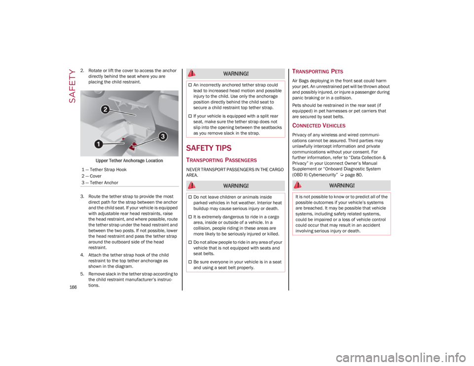
2. Rotate or lift the cover to access the anchor directly behind the seat where you are
placing the child restraint.
Upper Tether Anchorage Location
3. Route the tether strap to provide the most direct path for the strap between the anchor
and the child seat. If your vehicle is equipped
with adjustable rear head restraints, raise
the head restraint, and where possible, route
the tether strap under the head restraint and
between the two posts. If not possible, lower
the head restraint and pass the tether strap
around the outboard side of the head
restraint.
4. Attach the tether strap hook of the child restraint to the top tether anchorage as
shown in the diagram.
5. Remove slack in the tether strap according to the child restraint manufacturer’s instruc -
tions.
SAFETY TIPS
TRANSPORTING PASSENGERS
NEVER TRANSPORT PASSENGERS IN THE CARGO
AREA.
TRANSPORTING PETS
Air Bags deploying in the front seat could harm
your pet. An unrestrained pet will be thrown about
and possibly injured, or injure a passenger during
panic braking or in a collision.
Pets should be restrained in the rear seat (if
equipped) in pet harnesses or pet carriers that
are secured by seat belts.
CONNECTED VEHICLES
Privacy of any wireless and wired communi -
cations cannot be assured. Third parties may
unlawfully intercept information and private
communications without your consent. For
further information, refer to “Data Collection &
Privacy” in your Uconnect Owner’s Manual
Supplement or “Onboard Diagnostic System
(OBD II) Cybersecurity”
Ú
page 80.
1 — Tether Strap Hook
2 — Cover
3 — Tether Anchor
WARNING!
An incorrectly anchored tether strap could
lead to increased head motion and possible
injury to the child. Use only the anchorage
position directly behind the child seat to
secure a child restraint top tether strap.
If your vehicle is equipped with a split rear
seat, make sure the tether strap does not
slip into the opening between the seatbacks
as you remove slack in the strap.
WARNING!
Do not leave children or animals inside
parked vehicles in hot weather. Interior heat
buildup may cause serious injury or death.
It is extremely dangerous to ride in a cargo
area, inside or outside of a vehicle. In a
collision, people riding in these areas are
more likely to be seriously injured or killed.
Do not allow people to ride in any area of your
vehicle that is not equipped with seats and
seat belts.
Be sure everyone in your vehicle is in a seat
and using a seat belt properly.
WARNING!
It is not possible to know or to predict all of the
possible outcomes if your vehicle’s systems
are breached. It may be possible that vehicle
systems, including safety related systems,
could be impaired or a loss of vehicle control
could occur that may result in an accident
involving serious injury or death.
23_GA_OM_EN_USC_t.book Page 166
Page 201 of 248

199
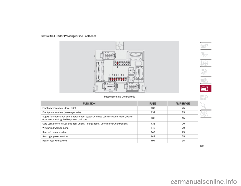
Control Unit Under Passenger Side Footboard
Passenger Side Control Unit
FUNCTIONFUSEAMPERAGE
Front power window (driver side)F3325
Front power window (passenger side) F3425
Supply for Information and Entertainment system, Climate Control system, Alarm, Power
door mirror folding, EOBD system, USB port F36
15
Safe Lock device (driver side door unlock – if equipped), Doors unlock, Central lock F3820
Windshield washer pump F4320
Rear left power window F4725
Rear right power window F4825
Heater rear window coil F9415
23_GA_OM_EN_USC_t.book Page 199