2023 ALFA ROMEO GIULIA brakes
[x] Cancel search: brakesPage 105 of 248

103
(Continued)
To Resume
Once the system has been canceled but not
deactivated, to resume a previously set speed,
simply push the RES/SET switch upward and
remove your foot from the accelerator to recall it.
The system will be set to the last stored speed.
Setting The Distance Between Vehicles
The distance between your vehicle and the
vehicle ahead may be set to one bar (short), two
bars (medium), three bars (long), or four bars
(maximum).Distance Icons The distances from the vehicle ahead are propor
-
tional to speed.
The interval of time with relation to the vehicle
ahead remains constant and varies from one
second (for the short distance one-bar setting) to
two seconds (for the maximum distance four-bar
setting).
The set distance is shown on the display by a
dedicated icon.
The setting is four bars (maximum) the first time
the system is used. After the distance has been
modified by the driver, the new distance will be
stored even if the system is deactivated and
reactivated.
To Decrease The Distance
Push and release the distance button to decrease
the distance setting. The distance setting
decreases by one bar (shorter) every time the
button is pushed.
Distance Button
The set speed is held if there are no vehicles
ahead. Once the shortest distance has been
selected, the next push of the button will set the
maximum distance. If a slower vehicle is detected in the same lane,
the vehicle icon on the display illuminates from
grey to white. The system automatically adjusts
the vehicle’s speed to keep the set distance,
independently of the set speed.
The vehicle holds the set distance until:
The vehicle ahead accelerates to a speed
higher than the set speed.
The vehicle ahead leaves the lane or the
detection field of the Adaptive Cruise Control
system sensor.
The distance setting is changed.
The Adaptive Cruise Control system is
deactivated/paused.
WARNING!
The Resume function should only be used if
traffic and road conditions permit. Resuming a
set speed that is too high or too low for
prevailing traffic and road conditions could
cause the vehicle to accelerate or decelerate
too sharply for safe operation. Failure to follow
these warnings can result in a collision and
death or serious personal injury.
WARNING!
The maximum braking applied by the system
is limited. The driver may apply the brakes in
all cases if needed.
If the system predicts that the braking level is
insufficient to hold the set distance, either
“BRAKE!” or a dedicated message is
displayed to warn the driver of approaching
the vehicle ahead. An acoustic signal is also
emitted. In this case, it is advised to brake
immediately as necessary to hold a safe
distance from the vehicle ahead.
The driver is responsible for ensuring that
there are no pedestrians, other vehicles or
objects along the direction of the vehicle.
Failure to comply with these precautions may
cause serious accidents and injuries.
23_GA_OM_EN_USC_t.book Page 103
Page 107 of 248

105
NOTE:
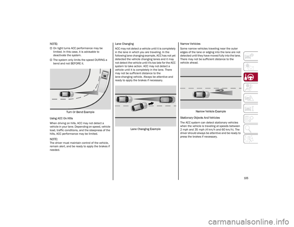
On tight turns ACC performance may be
limited. In this case, it is advisable to
deactivate the system.
The system only limits the speed DURING a
bend and not BEFORE it.Turn Or Bend Example
Using ACC On Hills
When driving on hills, ACC may not detect a
vehicle in your lane. Depending on speed, vehicle
load, traffic conditions, and the steepness of the
hills, ACC performance may be limited.
NOTE:
The driver must maintain control of the vehicle,
remain alert, and be ready to apply the brakes if
needed. Lane Changing
ACC may not detect a vehicle until it is completely
in the lane in which you are traveling. In the
following lane changing example, ACC has not yet
detected the vehicle changing lanes and it may
not detect the vehicle until it's too late for the ACC
system to take action. ACC may not detect a
vehicle until it is completely in the lane. There
may not be sufficient distance to the
lane-changing vehicle. Always be attentive and
ready to apply the brakes if necessary.
Lane Changing Example Narrow Vehicles
Some narrow vehicles traveling near the outer
edges of the lane or edging into the lane are not
detected until they have moved fully into the lane.
There may not be sufficient distance to the
vehicle ahead.
Narrow Vehicle Example
Stationary Objects And Vehicles
The ACC system can detect stationary vehicles
when the vehicle is traveling at speeds between
2 mph and 35 mph (4 km/h and 60 km/h). The
driver should always be attentive and be ready to
press the brakes if necessary.
23_GA_OM_EN_USC_t.book Page 105
Page 117 of 248

115
INDICATIONS ON THE DISPLAY
The system status is indicated by a white or green
icon in the instrument cluster display (similar to
the Adaptive Cruise Control (ACC) device) to the
left of the road sign indications provided by the
Traffic Sign Recognition (TSR) system.
ACCEPTANCE/REJECTION OF THE
S
UGGESTED SPEED
The system can be activated if the driver has
activated the following systems beforehand:
Adaptive Cruise Control (ACC)
Traffic Sign Recognition (TSR)
When these systems are active, a telltale will
display in the instrument cluster display
indicating the suggested speed provided by the
TSR system. The driver has the option to accept or
reject this using the RES/SET switch on the
steering wheel.
To accept the proposed speed and adjust the
speed set by ACC, move the RES/SET switch up or
down in the direction indicated in the telltale.
To reject the proposed speed, move the RES/SET
switch up or down in the direction opposite of the
arrow in the telltale. The ACC system will continue
to regulate to the previously set speed.
If the speed set by the ACC system is the same as
the speed detected by the TSR system, the speed
limit indicator on the instrument cluster display
will be highlighted with a green circle. 1 — Suggested Speed Higher Than Current Speed
2 — Suggested Speed Lower Than Current Speed
1 — Road Sign Recognized
PARKSENSE FRONT/REAR
PARK ASSIST SYSTEM —
IF EQUIPPED
The ParkSense system provides visual and
audible indications of the distance between the
rear, and if equipped, the front fascia/bumper
and a detected obstacle when backing up or
moving forward (e.g. during a parking maneuver).
The vehicle brakes may be automatically applied
and released when performing a reverse parking
maneuver if the system detects a possible
collision with an obstacle.
When the REVERSE gear is engaged and the
system is on, the front and rear sensors are
activated. If the vehicle moves from REVERSE to
a forward gear, the rear sensors are deactivated,
while the front sensors remain active until the
speed of 9 mph (15 km/h) is exceeded.
NOTE:
In certain operating conditions, the system could
start detecting an obstacle only after the vehicle
has moved slightly (a few inches).
WARNING!
Drivers must be careful when backing up even
when using the ParkSense system. Always
check carefully behind your vehicle, and be
sure to check for pedestrians, animals, other
vehicles, obstructions, or blind spots before
backing up. You are responsible for the safety
of your surroundings and must continue to pay
attention while backing up. Failure to do so
can result in serious injury or death.
23_GA_OM_EN_USC_t.book Page 115
Page 128 of 248

STARTING AND OPERATING
126
A Month-Day-Hour (MDH) number is included on
this label and indicates the Month, Day and Hour
of manufacture. The bar code that appears on
the bottom of the label is your VIN.
Gross Vehicle Weight Rating (GVWR)
The GVWR is the total permissible weight of your
vehicle including driver, passengers, vehicle,
options and cargo. The label also specifies
maximum capacities of front and rear axle
systems (GAWR). Total load must be limited so
GVWR and front and rear GAWR are not
exceeded.
Payload
The payload of a vehicle is defined as the
allowable load weight a truck can carry, including
the weight of the driver, all passengers, options
and cargo.
Gross Axle Weight Rating (GAWR)
The GAWR is the maximum permissible load on
the front and rear axles. The load must be
distributed in the cargo area so that the GAWR of
each axle is not exceeded.
Each axle GAWR is determined by the
components in the system with the lowest load
carrying capacity (axle, springs, tires or wheels).
Heavier axles or suspension components
sometimes specified by purchasers for increased
durability do not necessarily increase the
vehicle's GVWR.
Tire Size
The tire size on the Vehicle Certification Label
represents the actual tire size on your vehicle.
Replacement tires must be equal to the load
capacity of this tire size.
Rim Size
This is the rim size that is appropriate for the tire
size listed.
Inflation Pressure
This is the cold tire inflation pressure for your
vehicle for all loading conditions up to full GAWR.
Curb Weight
The curb weight of a vehicle is defined as the total
weight of the vehicle with all fluids, including
vehicle fuel, at full capacity conditions, and with
no occupants or cargo loaded into the vehicle.
The front and rear curb weight values are
determined by weighing your vehicle on a
commercial scale before any occupants or cargo
are added.
Loading
The actual total weight and the weight of the front
and rear of your vehicle at the ground can best be
determined by weighing it when it is loaded and
ready for operation.
The entire vehicle should first be weighed on a
commercial scale to ensure that the GVWR has
not been exceeded. The weight on the front and
rear of the vehicle should then be determined
separately to be sure that the load is properly
distributed over the front and rear axle. Weighing
the vehicle may show that the GAWR of either the
front or rear axles has been exceeded but the
total load is within the specified GVWR. If so,
weight must be shifted from front to rear or rear
to front as appropriate until the specified weight
limitations are met. Store the heavier items down
low and be sure that the weight is distributed
equally. Stow all loose items securely before
driving.Improper weight distributions can have an
adverse effect on the way your vehicle steers and
handles and the way the brakes operate.
TRAILER TOWING
Trailer towing is not recommended for this
vehicle.
SUGGESTIONS FOR
DRIVING
SAVING FUEL
The following are some suggestions which may
help you save fuel and lower the amount of
harmful emissions released into the atmosphere.
Vehicle Maintenance
Checks and operations should be carried out in
accordance with the Maintenance Plan
Ú
page 182.
Tires
Check the tire pressures at least once every four
weeks: if the pressure is too low, consumption
levels increase as resistance to rolling is higher.
WARNING!
Do not load your vehicle any heavier than the
GVWR or the maximum front and rear GAWR. If
you do, parts on your vehicle can break, or it
can change the way your vehicle handles. This
could cause you to lose control. Overloading
can shorten the life of your vehicle.
23_GA_OM_EN_USC_t.book Page 126
Page 130 of 248

STARTING AND OPERATING
128
EXHAUST GAS
Exhaust emissions are very dangerous, and may
be lethal. They contain carbon monoxide, a
colorless, odorless gas which can cause fainting
and poisoning if inhaled.
To avoid inhaling carbon monoxide, take the
following measures:
Do not keep the engine running in closed
spaces.
If, for some reason (e.g. transporting bulky
loads), it is necessary to drive with the trunk
open, close all the windows and run the
climate control fan at maximum speed. DO
NOT activate air recirculation mode.
Should it be necessary to stay in the stationary
vehicle with engine running, adjust the
ventilation/heating system and operate the
fan in such a way that outside air will enter the
passenger compartment. Activate the
maximum fan speed.
Maintenance of the exhaust system provides the
best protection against leaks of carbon monoxide
into the passenger compartment.
Should an unusual noise from the exhaust
system or the presence of exhaust gas in the
passenger compartment be identified, or if the
underbody or rear section of the vehicle is
damaged, have the entire exhaust system and
bodywork areas checked to identify any
components which are broken, damaged, worn or
have moved from their correct fitting position. If
any of these things occur, contact an authorized
dealer. Open welding or loose connections may permit
exhaust gas to enter the passenger
compartment.
Check the exhaust system each time the vehicle
is raised for lubrication or oil change operations.
Replace the components if necessary, contact an
authorized dealer.
PERFORMANCE — QUADRIFOGLIO
This vehicle is equipped with an engine capable
of delivering exceptionally fast acceleration and
speed:
Peak power: 505 HP at 6500 RPM.
Peak torque: 443 ft-lb at 2500–5000 RPM.
Top speed: 191 mph (307 km/h).
Acceleration from 0 to 60 mph (0 to 100 km/h):
3.8 seconds.
For safe driving, it is essential, particularly during
the first days of use, to get to know the car by
driving carefully and gradually discovering its
performance. Driving On Race Tracks
Before driving on a track using a racing style, it is
necessary to:
Attend a race track driving course.
Check all liquid levels in the engine
compartment.
Have the car inspected at an authorized
dealer.
Remember that the car was not designed to be
driven exclusively on the race track and that this
use increases stress and component wear.
NOTE:
Quadrifoglio front brakes are equipped with NAO
type pads (Non-Asbestos Organic). These pads
are NOT suitable for high thermal loads (for
example track use).
23_GA_OM_EN_USC_t.book Page 128
Page 131 of 248

129
(Continued)
This very important section describes the safety
syst
e
ms that your vehicle may be equipped with,
and provides instructions on how to use them
correctly.
ACTIVE SAFETY SYSTEMS
The vehicle may be equipped with the following
active safety devices:
Anti-Lock Brake System (ABS)
Active Torque Vectoring (ATV)
Dynamic Steering Torque (DST)
Drive Train Control (DTC)
Electronic Stability Control (ESC)
Hill Start Assist (HSA)
Panic Brake Assist (PBA)
Traction Control System (TCS)
For the operation of the systems, see the
following pages.
ANTI-LOCK BRAKE SYSTEM (ABS)
An integral part of the braking system, the ABS
prevents one or more wheels from locking and
slipping in all road surface conditions, regardless
of the intensity of the braking action. The system
ensures that the vehicle can be controlled even
during emergency braking, allowing the driver to
optimize stopping distances.
The system intervenes during braking when the
wheels are about to lock, typically in emergency
braking or low-grip conditions where locking may
be more frequent. The system also improves control and stability of
the vehicle when braking on a surface where the
grip of the left and right wheels varies, such as in
a corner.
The Electronic Braking Force Distribution (EBD)
system works with the ABS, allowing the brake
force to be distributed between the front and rear
wheels.
System Intervention
The ABS equipped on this vehicle is provided with
the "Brake-by-wire" (Integrated Brake System —
IBS) function. With this system, the command
given by pressing the brake pedal is not
transmitted hydraulically, but electrically.
Therefore, the light pulsation that is felt on the
pedal with the traditional system is no longer
noticeable.
ACTIVE TORQUE VECTORING (ATV) —
I
F EQUIPPED
The dynamic drive control is used to optimize and
balance the drive torque between the wheels of
the same axles. The ATV system improves the grip
in turns, sending more drive torque to the
external wheel.
Given that, in a turn, the external wheels of the
car travel more than the internal ones and
therefore turn faster, sending a higher thrust to
the external rear wheel allows for the car to be
more stable and to not suffer an "understeer"
condition. Understeer occurs when the vehicle is
turning less than appropriate for the steering
wheel position.
WARNING!
The ABS contains sophisticated electronic
equipment that may be susceptible to
interference caused by improperly installed
or high output radio transmitting equipment.
This interference can cause possible loss of
anti-lock braking capability. Installation of
such equipment should be performed by
qualified professionals.
Pumping of the Anti-Lock Brakes will
diminish their effectiveness and may lead to
a collision. Pumping makes the stopping
distance longer. Just press firmly on your
brake pedal when you need to slow down or
stop.
The ABS cannot prevent the natural laws of
physics from acting on the vehicle, nor can it
increase braking or steering efficiency
beyond that afforded by the condition of the
vehicle brakes and tires or the traction
afforded.
The ABS cannot prevent collisions, including
those resulting from excessive speed in
turns, following another vehicle too closely,
or hydroplaning.
The capabilities of an ABS equipped vehicle
must never be exploited in a reckless or
dangerous manner that could jeopardize the
user’s safety or the safety of others.
WARNING!
23_GA_OM_EN_USC_t.book Page 129
Page 132 of 248

SAFETY
130
DYNAMIC STEERING TORQUE (DST)
DST uses the integration of the Electronic
Stability Control (ESC) system with the electric
power steering to increase the safety level of the
whole vehicle.
In critical situations (braking on surfaces with
different grip conditions), the ESC system
controls the steering through the DST function to
implement an additional torque contribution on
the steering wheel in order to suggest the most
correct maneuver to the driver.
The coordinated action of the brakes and
steering increases the sensation of safety and
control of the vehicle.
NOTE:
The DST feature is only meant to help the driver
realize the correct course of action through small
torques on the steering wheel, which means the
effectiveness of the DST feature is highly depen-
dent on the driver’s sensitivity and overall reac -
tion to the applied torque. It is very important to
realize that this feature will not steer the vehicle,
meaning the driver is still responsible for steering
the vehicle.
DRIVE TRAIN CONTROL (DTC) SYSTEM —
I
F EQUIPPED
Some models of this vehicle are equipped with an
All-Wheel Drive (AWD) system, which offers an
optimal drive for countless driving conditions and
road surfaces. The system reduces the slipping of
the tires to a minimum, automatically
redistributing the torque to the front and rear
wheels as needed. To maximize fuel savings, the vehicle with AWD
automatically passes to Rear-Wheel Drive (RWD)
when the road and environmental conditions are
such that they wouldn't cause the tires to slip.
When the road and environmental conditions
require better traction, the vehicle automatically
goes to AWD mode.
NOTE:
If the system failure symbol switches on, after
starting the engine or while driving, it means that
the AWD system is not working properly. If the
warning message activates frequently, it is
recommended to carry out the maintenance
operations.
ELECTRONIC STABILITY CONTROL (ESC)
The ESC system improves the directional control
and stability of the vehicle in various driving
conditions.
The ESC system corrects the vehicle’s understeer
and oversteer, distributing the brake force on the
appropriate wheels. The torque supplied by the
engine can also be reduced in order to maintain
control of the vehicle.
Oversteer
occurs when the vehicle is turning
more than it should according to the angle of
the steering wheel.
Understeer occurs when the vehicle is turning
less than it should according to the angle of
the steering wheel.
The ESC system uses sensors installed on the
vehicle to determine the path that the driver
intends to follow and compares it with the
vehicle’s effective path. When the real path
deviates from the desired path, the ESC system
intervenes to counteract these conditions. System Intervention
The intervention of the system is indicated by the
flashing of the ESC Warning Light on the
instrument panel, to inform the driver that the
vehicle stability and grip are critical.
WARNING!
Electronic Stability Control (ESC) cannot
prevent the natural laws of physics from
acting on the vehicle, nor can it increase the
traction afforded by prevailing road
conditions. ESC cannot prevent accidents,
including those resulting from excessive
speed in turns, driving on very slippery
surfaces, or hydroplaning. ESC also cannot
prevent accidents resulting from loss of
vehicle control due to inappropriate driver
input for the conditions. Only a safe, attentive,
and skillful driver can prevent accidents. The
capabilities of an ESC equipped vehicle must
never be exploited in a reckless or dangerous
manner which could jeopardize the user’s
safety or the safety of others.
Vehicle modifications, or failure to properly
maintain your vehicle, may change the
handling characteristics of your vehicle, and
may negatively affect the performance of the
ESC system. Changes to the steering system,
suspension, braking system, tire type and
size or wheel size may adversely affect ESC
performance. Improperly inflated and
unevenly worn tires may also degrade ESC
performance. Any vehicle modification or
poor vehicle maintenance that reduces the
effectiveness of the ESC system can
increase the risk of loss of vehicle control,
vehicle rollover, personal injury and death.
23_GA_OM_EN_USC_t.book Page 130
Page 140 of 248

SAFETY
138
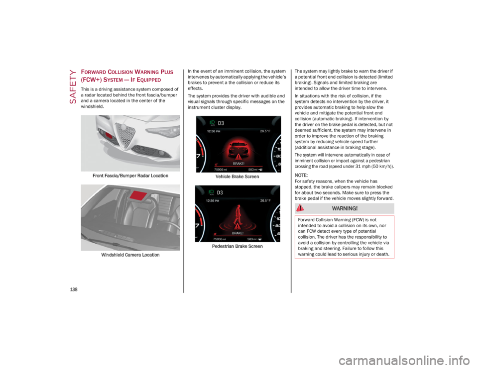
FORWARD COLLISION WARNING PLUS
(FCW+) S
YSTEM — IF EQUIPPED
This is a driving assistance system composed of
a radar located behind the front fascia/bumper
and a camera located in the center of the
windshield.
Front Fascia/Bumper Radar Location
Windshield Camera Location In the event of an imminent collision, the system
intervenes by automatically applying the vehicle’s
brakes to prevent a the collision or reduce its
effects.
The system provides the driver with audible and
visual signals through specific messages on the
instrument cluster display.
Vehicle Brake Screen
Pedestrian Brake Screen The system may lightly brake to warn the driver if
a potential front end collision is detected (limited
braking). Signals and limited braking are
intended to allow the driver time to intervene.
In situations with the risk of collision, if the
system detects no intervention by the driver, it
provides automatic braking to help slow the
vehicle and mitigate the potential front end
collision (automatic braking). If intervention by
the driver on the brake pedal is detected, but not
deemed sufficient, the system may intervene in
order to improve the reaction of the braking
system by reducing vehicle speed further
(additional assistance in braking stage).
The system will intervene automatically in case of
imminent collision or impact against a pedestrian
crossing the road (speed under 31 mph (50 km/h)).
NOTE:
For safety reasons, when the vehicle has
stopped, the brake calipers may remain blocked
for about two seconds. Make sure to press the
brake pedal if the vehicle moves slightly forward.
WARNING!
Forward Collision Warning (FCW) is not
intended to avoid a collision on its own, nor
can FCW detect every type of potential
collision. The driver has the responsibility to
avoid a collision by controlling the vehicle via
braking and steering. Failure to follow this
warning could lead to serious injury or death.
23_GA_OM_EN_USC_t.book Page 138