Page 65 of 112

Periodic maintenance an d a djustment
7-8
7
EAU80531
TIPAir filter
This model’s air filter uses a disposable oil-coated paper element. This element cannot be cleaned with compressed
air, doing so will only damage it.
The air filter element needs to be replaced more frequently when riding in unusually wet or dusty areas.
Hydraulic brake service Regularly check the front and rear brake fluid levels. Replenish if necessary.
Every two years replace the rear brake master cylinder, the internal components of the front brake master cylinder, the
brake calipers, and change the brake fluid.
Replace the brake hoses every four years or sooner if cracked or damaged.30 *Throttle g
rip hous-
in g an d ca ble • Check operation and free play.
• Adjust the throttle cable free play
if necessary.
• Lubricate the throttle grip housing and cable. √√√√√
31 *Li
ghts, si gnals an d
switches • Check operation.
• Adjust headlight beam.
√√√√√√
NO. ITEM CHECK OR MAINTENANCE JOB
ODOMETER READING
ANNUAL
CHECK
1000 km
(600 mi) 10000 km
(6000 mi) 20000 km
(12000 mi) 30000 km
(18000 mi) 40000 km
(24000 mi)
UBN6EBE0.book Page 8 Tuesday, October 19, 2021 8:35 AM
Page 66 of 112
Periodic maintenance an d a djustment
7-9
7
EAU18713
Removin g an d installin g cowl-
in gs an d panelsThe cowlings and panels shown need
to be removed to perform some of the
maintenance jobs described in this
chapter. Refer to this section each time
a cowling or panel needs to be re-
moved and installed.
EAU79983
Cowlin g A
To remove the cowling1. Remove panel A. (See page 7-13.)
2. Remove the bolts, quick fasten- ers, and quick fastener screw.
1. Cowling A
2. Cowling B
1
2
1. Cowling C
2. Cowling a
1. Panel A
2. Panel B
1
2
1
2
1. Cowling A
2. Bolt
3. Quick fastener screw
1
3
2
2
UBN6EBE0.book Page 9 Tuesday, October 19, 2021 8:35 AM
Page 67 of 112
Periodic maintenance an d a djustment
7-10
7
3. Slide the cowling as shown. 4. Remove the upper projections
from the slots, and then slide the
cowling forward.
To install the cowling
1. Slide the cowling rearward, and then fit the upper projections into
the slots. 2. Slide the cowling as shown.
3. Install the bolts, quick fasteners,
and quick fastener screw.
1. Bolt
1. Quick fastener
1
1
1. Cowling A
1. Cowling A
1
1
1. Cowling A
1. Cowling A
1
1
UBN6EBE0.book Page 10 Tuesday, October 19, 2021 8:35 AM
Page 68 of 112
Periodic maintenance an d a djustment
7-11
7
TIPInstall the bolts loosely, then install the
quick fasteners and quick fastener
screw, and then tighten the bolts.4. Install the panel.
Cowlin g B
To remove the cowling1. Remove panel A and cowling A. (See page 7-13.)
2. Remove cowling B by removing the bolts. To install the cowling
1. Place cowling B in its original po-
sition, and then install the bolts.
2. Install cowling A and panel A.
Cowlin g C
To remove the cowling1. Remove panel B. (See page 7-13.)
2. Remove the bolts, quick fastener, and quick fastener screw.
3. Slide the cowling as shown.
1. Cowling B
2. Bolt
12 2
1. Cowling C
2. Bolt
3. Quick fastener screw
1
2
2
3
1. Bolt
1. Quick fastener
1
1
UBN6EBE0.book Page 11 Tuesday, October 19, 2021 8:35 AM
Page 69 of 112
Periodic maintenance an d a djustment
7-12
7
4. Remove the cowling by removing
the upper projections from the
slots.
To install the cowling
1. Fit the upper projections into the slots. 2. Slide the cowling as shown.
3. Install the bolts, quick fastener,
and quick fastener screw.
TIPInstall the bolts loosely, then install the
quick fastener and quick fastener
screw, and then tighten the bolts.4. Install the panel.
Cowlin g D
To remove the cowling1. Remove panel B and cowling C. (See page 7-13.)
2. Remove cowling D by removing the bolts.
1. Cowling C
1. Cowling C
11
1. Cowling C
1. Cowling C
11
1. Cowling a
2. Bolt
2
12
UBN6EBE0.book Page 12 Tuesday, October 19, 2021 8:35 AM
Page 70 of 112

Periodic maintenance an d a djustment
7-13
7 To install the cowling
1. Place cowling D in its original po-
sition, and then install the bolts.
2. Install cowling C and panel B.
EAU79970
Panels A an d B
To remove a panelRemove the quick fasteners, and then
pull the panel off as shown.
To install a panelPlace the panel in the original position,
and then install the quick fasteners.
EAU19653
Checkin g the spark plu gsThe spark plugs are important engine
components, which should be
checked periodically, preferably by a
Yamaha dealer. Since heat and depos- its will cause any spark plug to slowly
erode, they should be removed and
checked in accordance with the peri-
odic maintenance and lubrication
chart. In addition, the condition of the
spark plugs can reveal the condition of
the engine.
The porcelain insulator around the
center electrode of each spark plug
should be a medium-to-light tan (the
ideal color when the vehicle is ridden
normally), and all spark plugs installed
in the engine should have the same
color. If any spark plug shows a dis-
tinctly different color, the engine could
be operating improperly. Do not at-
tempt to diagnose such problems
yourself. Instead, have a Yamaha deal-
er check the vehicle.
If a spark plug shows signs of elec-
trode erosion and excessive carbon or
other deposits, it should be replaced.
1. Panel A
2. Quick fastener
2
1
UBN6EBE0.book Page 13 Tuesday, October 19, 2021 8:35 AM
Page 71 of 112

Periodic maintenance an d a djustment
7-14
7
Before installing a spark plug, the
spark plug gap should be measured
with a wire thickness gauge and, if
necessary, adjusted to specification.
Clean the surface of the spark plug
gasket and its mating surface, and
then wipe off any grime from the spark
plug threads.
TIPIf a torque wrench is not available
when installing a spark plug, a good
estimate of the correct torque is 1/4…
1/2 turn past finger tight. However, the
spark plug should be tightened to the
specified torque as soon as possible.NOTICE
ECA10841
Do not use any tools to remove or in-
stall the spark plu
g cap, otherwise
the i gnition coil coupler may get
d amag ed . The spark plu g cap may
b e difficult to remove because the
ru bber seal on the en d of the cap fits
ti g htly. To remove the spark plu g
cap, simply twist it b ack and forth
while pullin g it out; to install it, twist
it back an d forth while pushin g it in.
EAU36112
CanisterThis model is equipped with a canister
to prevent the discharging of fuel vapor
into the atmosphere. Before operating
this vehicle, make sure to check the
following:
Check each hose connection.
Check each hose and canister for
cracks or damage. Replace if
damaged.
Make sure that the canister
breather is not blocked, and if
necessary, clean it.
Specifie d spark plu g:
NGK/CR10EK1. Spark plug gapSpark plu g g ap:
0.6–0.7 mm (0.024–0.028 in)
Ti ghtenin g torque:
Spark plug: 13 N·m (1.3 kgf·m, 9.6 lb·ft)
1
1
1. Canister
2. Canister breather
2
1
UBN6EBE0.book Page 14 Tuesday, October 19, 2021 8:35 AM
Page 72 of 112

Periodic maintenance an d a djustment
7-15
7
EAU80313
En gine oil an d oil filter car-
tri dgeThe engine oil level should be checked
before each ride. In addition, the oil
must be changed and the oil filter car-
tridge replaced at the intervals speci-
fied in the periodic maintenance and
lubrication chart.
To check the en gine oil level
1. Place the vehicle on a level sur- face and hold it in an upright posi-
tion. A slight tilt to the side can
result in a false reading.
2. Start the engine, warm it up for several minutes, and then turn it
off.
3. Wait a few minutes for the oil level to settle for an accurate reading.
4. Remove the engine oil dipstick and wipe it clean, insert it back
into the hole (without screwing it
in), and then remove it again to
check the oil level.TIPThe engine oil should be between the
minimum and maximum level marks.
5. Check the dipstick O-ring fordamage, and replace it if neces-
sary.
6. If the engine oil is at or below the minimum level mark, remove the
engine oil filler cap, and then add
sufficient oil of the recommended
type to raise it to the correct level. 7. Check the filler cap O-ring for
damage, and replace it if neces-
sary.
8. Insert and tighten the engine oil dipstick, and then install and tight-
en the oil filler cap.
To chan ge the en gine oil (with or
without oil filter cartri dge replace-
ment) 1. Place the vehicle on a level sur- face.
2. Remove cowlings A and B. (See page 7-9.)
3. Start the engine, warm it up for several minutes, and then turn it
off.1. Engine oil dipstick
2. O-ring
3. Maximum level mark
4. Minimum level mark
1
2
3
4
1. Engine oil filler cap
2. O-ring
1
2
1
UBN6EBE0.book Page 15 Tuesday, October 19, 2021 8:35 AM
 1
1 2
2 3
3 4
4 5
5 6
6 7
7 8
8 9
9 10
10 11
11 12
12 13
13 14
14 15
15 16
16 17
17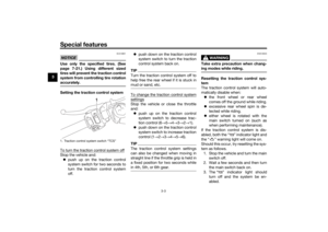 18
18 19
19 20
20 21
21 22
22 23
23 24
24 25
25 26
26 27
27 28
28 29
29 30
30 31
31 32
32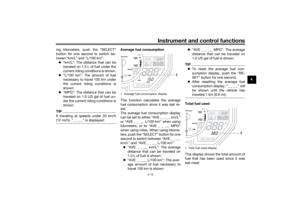 33
33 34
34 35
35 36
36 37
37 38
38 39
39 40
40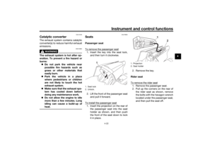 41
41 42
42 43
43 44
44 45
45 46
46 47
47 48
48 49
49 50
50 51
51 52
52 53
53 54
54 55
55 56
56 57
57 58
58 59
59 60
60 61
61 62
62 63
63 64
64 65
65 66
66 67
67 68
68 69
69 70
70 71
71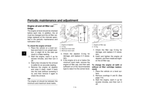 72
72 73
73 74
74 75
75 76
76 77
77 78
78 79
79 80
80 81
81 82
82 83
83 84
84 85
85 86
86 87
87 88
88 89
89 90
90 91
91 92
92 93
93 94
94 95
95 96
96 97
97 98
98 99
99 100
100 101
101 102
102 103
103 104
104 105
105 106
106 107
107 108
108 109
109 110
110 111
111


