2022 TOYOTA SIENNA HYBRID ESP
[x] Cancel search: ESPPage 507 of 600
5077-2. Steps to take in an emergency
7
When trouble arises
●The power switch mode is memo-
rized by the vehicle. When the 12-
volt battery is reconnected, the
system will return to the mode it
was in before the 12-volt battery
was discharged. Before discon-
necting the 12-volt battery, turn
the power switch off.
If you are unsure what mode the
power switch was in before the
12-volt battery discharged, be
especially careful when recon-
necting the 12-volt battery.
■When replacing the 12-volt bat-
tery
●Use a 12-volt battery that con-
forms to European regulations.
Use a battery that the case size is
same as the previous one (LN2),
20 hours rate capacity (20HR) is
equivalent (60Ah) or greater, and
performance rating (CCA) is
equivalent (563A) or greater.
• If the sizes differ, the 12-volt bat-
tery cannot be properly secured.
• If the 20 hour rate capacity is low,
even if the time period where the
vehicle is not used is a short time,
the 12-volt battery may discharge
and hybrid system may not be
able to start.
●Use a 12-volt battery with a han-
dle. If a 12-volt b attery without a
handle is used, removal is more
difficult.
●When removing the 12-volt bat-
tery: P.420
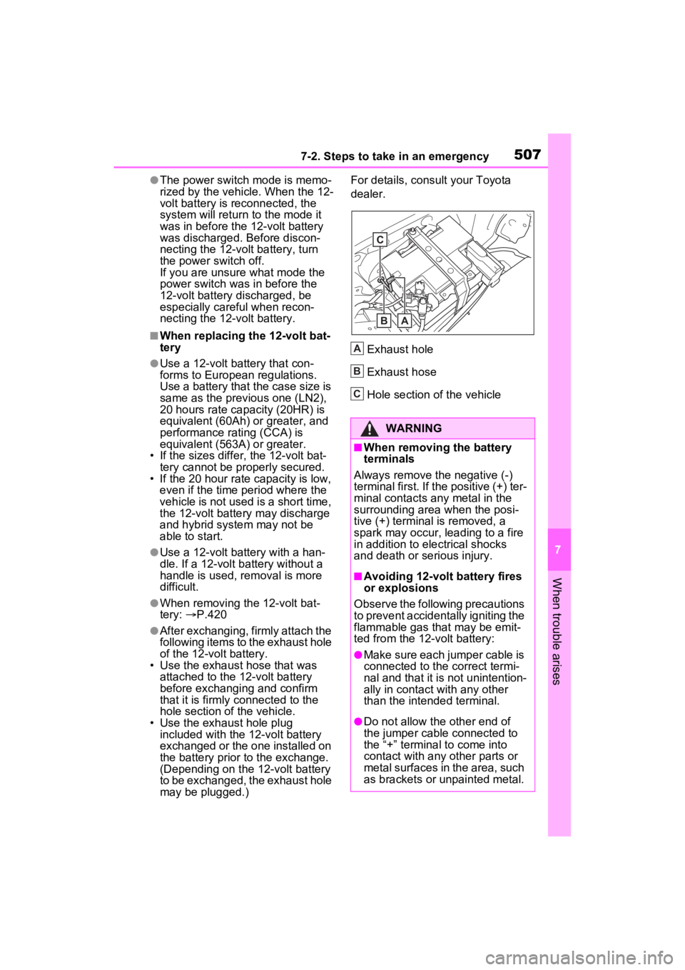
●After exchanging, firmly attach the
following items to the exhaust hole
of the 12-volt battery.
• Use the exhaust hose that was attached to the 12-volt battery
before exchangi ng and confirm
that it is firmly connected to the
hole section of the vehicle.
• Use the exhaust hole plug
included with the 12-volt battery
exchanged or the one installed on
the battery prior to the exchange.
(Depending on the 12-volt battery
to be exchanged, the exhaust hole
may be plugged.) For details, consu
lt your Toyota
dealer.
Exhaust hole
Exhaust hose
Hole section of the vehicle
WARNING
■When removing the battery
terminals
Always remove the negative (-)
terminal first. If the positive (+) ter-
minal contacts any metal in the
surrounding area when the posi-
tive (+) terminal is removed, a
spark may occur, leading to a fire
in addition to ele ctrical shocks
and death or serious injury.
■Avoiding 12-volt battery fires
or explosions
Observe the following precautions
to prevent accidentally igniting the
flammable gas that may be emit-
ted from the 12-volt battery:
●Make sure each jumper cable is
connected to the correct termi-
nal and that it is not unintention-
ally in contact with any other
than the intended terminal.
●Do not allow the other end of
the jumper cable connected to
the “+” terminal to come into
contact with any other parts or
metal surfaces in the area, such
as brackets or unpainted metal.
C
BA
A
B
C
Page 512 of 600
5127-2. Steps to take in an emergency
Toyota dealer.
WARNING
■When inspecting under the
hood of your vehicle
Observe the following precau-
tions.
Failure to do so may result in seri-
ous injury such as burns.
●If steam is seen coming from
under the hood, do not open the
hood until the steam has sub-
sided. The engine compart-
ment may be very hot.
●After the hybrid system has
been turned off, check that the
“READY” indicator is off.
When the hybrid system is oper-
ating, the gasoline engine may
automatically start, or the cool-
ing fan may suddenly operate
even if the gasoline engine
stops. Do not touch or approach
rotating parts such as the fan,
which may lead to fingers or
clothing (especially a tie, a scarf
or a muffler) getting caught,
resulting in serious injury.
●Do not loosen the coolant reser-
voir cap while the hybrid system
and radiator are hot.
High temperature steam or
coolant could spray out.
NOTICE
■When adding engine/power
control unit coolant
Add coolant slowly after the
hybrid system has cooled down
sufficiently. Adding cool coolant to
a hot hybrid system too quickly
can cause damage to the hybrid
system.
■To prevent damage to the
cooling system
Observe the following precau-
tions:
●Avoid contaminating the coolant
with foreign matter (such as
sand or dust, etc.).
●Do not use any coolant additive.
Page 532 of 600
5328-1. Specifications
■Temperature A, B, C
The temperature grades are A
(the highest), B, and C, repre-
senting the tire’s resistance to
the generation of heat and its
ability to dissipate heat when
tested under controlled condi-
tions on a specified indoor labo-
ratory test wheel.
Sustained high temperature can
cause the material of the tire to
degenerate and reduce tire life, and
excessive temperature can lead to
sudden tire failure.
Grade C corresponds to a level of performance which all passenger
car tires must meet under the Fed-
eral Motor Vehicle Safety Standard
No. 109.
Grades B and A represent higher
levels of performance on the labo-
ratory test wheel than the minimum
required by law.
Warning: The temperature grades
of a tire assume tha
t it is properly
inflated and not overloaded.
Excessive speed, underinflation, or
excessive loading, either sepa-
rately or in combination, can cause
heat buildup and possible tire fail-
ure.
Glossary of tire terminology
Tire related termMeaning
Cold tire inflation pres-
sureTire pressure when the vehicle has been parked
for three hours or more, or has not been driven
more than 1 mile or 1.5 km under that condition
Maximum inflation pres-
sureThe maximum cold inflated pressure to which a
tire may be inflated, shown on the sidewall of
the tire
Recommended inflation
pressureCold tire inflation pressure recommended by a
manufacturer
Accessory weight
The combined weight (in excess of those stan-
dard items which may be replaced) of transmis-
sion, power steering, power brakes, power
windows, power seats, radio and heater, to the
extent that these items are available as factory-
installed equipment (whether installed or not)
Curb weight
The weight of a motor vehicle with standard
equipment, including th e maximum capacity of
fuel, oil and coolant, and if so equipped, air con-
ditioning and additional weight optional engine
Page 534 of 600
5348-1. Specifications
Weather sideThe surface area of the rim not covered by the
inflated tire
Bead
The part of the tire that is made of steel wires,
wrapped or reinforced by ply cords and that is
shaped to fit the rim
Bead separationA breakdown of the bond between components
in the bead
Bias ply tire
A pneumatic tire in whic h the ply cords that
extend to the beads are la id at alternate angles
substantially less than 9 0 degrees to the center-
line of the tread
CarcassThe tire structure, except tread and sidewall
rubber which, when inflated, bears the load
ChunkingThe breaking away of pieces of the tread or
sidewall
CordThe strands forming th e plies in the tire
Cord separationThe parting of cords from adjacent rubber com-
pounds
CrackingAny parting withi n the tread, sidewall, or inner-
liner of the tire extend ing to cord material
CT
A pneumatic tire with an inverted flange tire and
rim system in which the rim is designed with rim
flanges pointed radially inward and the tire is
designed to fit on the underside of the rim in a
manner that encloses the rim flanges inside the
air cavity of the tire
Extra load tire
A tire designed to operate at higher loads and at
higher inflation pressures than the correspond-
ing standard tire
GrooveThe space between two adjacent tread ribs
Innerliner
The layer(s) forming th e inside surface of a
tubeless tire that contains the inflating medium
within the tire
Innerliner separationThe parting of the innerliner from cord material
in the carcass
Tire related termMeaning
Page 536 of 600
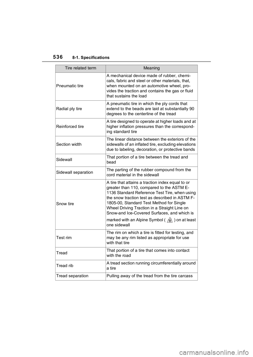
5368-1. Specifications
Pneumatic tire
A mechanical device made of rubber, chemi-
cals, fabric and steel or other materials, that,
when mounted on an aut omotive wheel, pro-
vides the traction and co ntains the gas or fluid
that sustains the load
Radial ply tire
A pneumatic tire in whic h the ply cords that
extend to the beads are laid at substantially 90
degrees to the centerline of the tread
Reinforced tire
A tire designed to operate at higher loads and at
higher inflation pressures than the correspond-
ing standard tire
Section width
The linear distance between the exteriors of the
sidewalls of an inflated tire, excluding elevations
due to labeling, decoratio n, or protective bands
SidewallThat portion of a tire between the tread and
bead
Sidewall separationThe parting of the rubber compound from the
cord material in the sidewall
Snow tire
A tire that attains a traction index equal to or
greater than 110, compared to the ASTM E-
1136 Standard Reference Test Tire, when using
the snow traction test a s described in ASTM F-
1805-00, Standard Test Method for Single
Wheel Driving Traction i n a Straight Line on
Snow-and Ice-Covered Su rfaces, and which is
marked with an Alpine Symbol ( ) on at least
one sidewall
Test rim
The rim on which a tire is fitted for testing, and
may be any rim listed as appropriate for use
with that tire
TreadThat portion of a tire t hat comes into contact
with the road
Tread ribA tread section running circumferentially around
a tire
Tread separationPulling away of the tread from the tire carcass
Tire related termMeaning
Page 563 of 600
5639-1. For owners
9
For owners
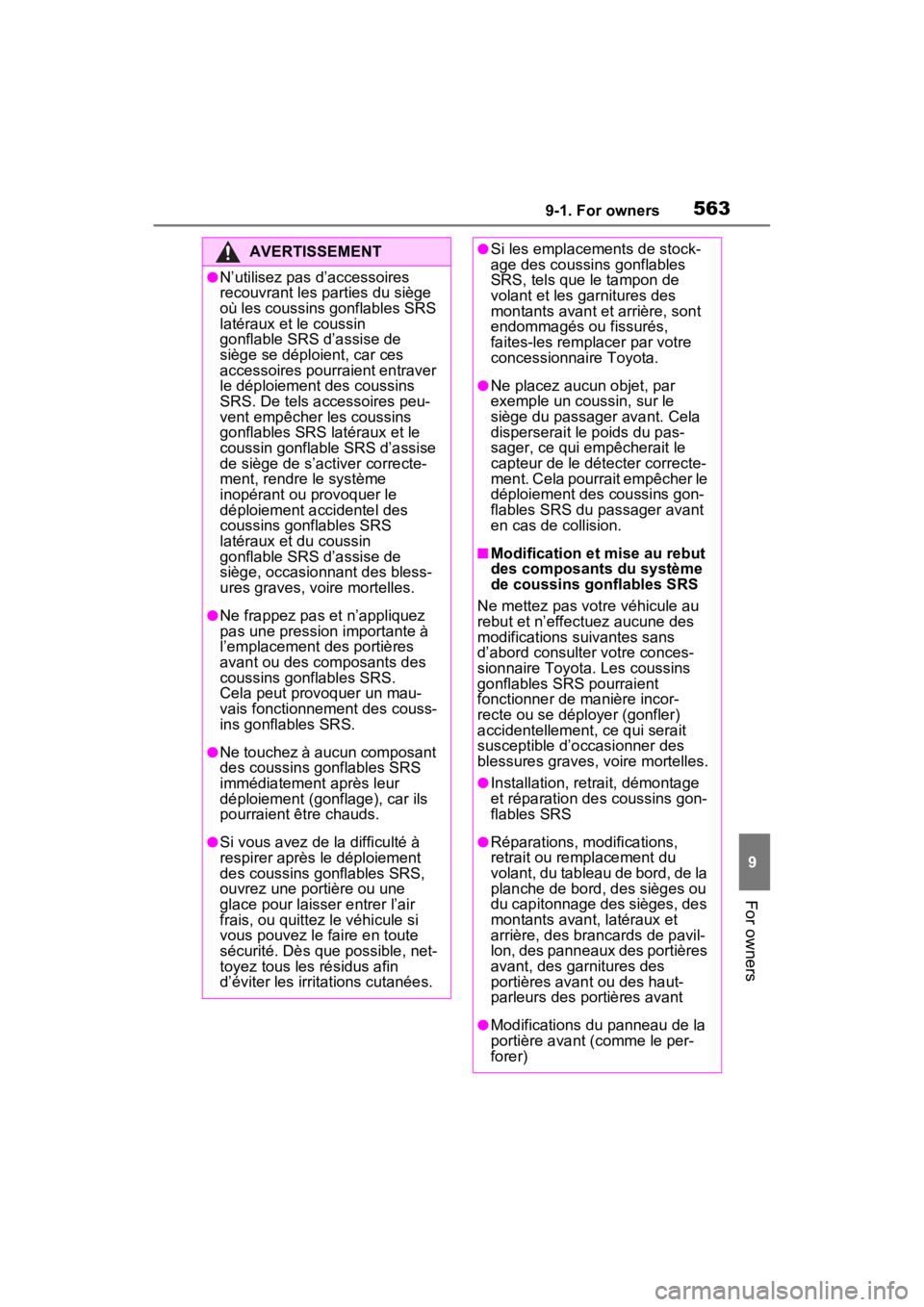
AVERTISSEMENT
●N’utilisez pas d’accessoires
recouvrant les parties du siège
où les coussins gonflables SRS
latéraux et le coussin
gonflable SRS d’assise de
siège se déploient, car ces
accessoires pourraient entraver
le déploiement des coussins
SRS. De tels accessoires peu-
vent empêcher les coussins
gonflables SRS latéraux et le
coussin gonflable SRS d’assise
de siège de s’activer correcte-
ment, rendre le système
inopérant ou provoquer le
déploiement accidentel des
coussins gonflables SRS
latéraux et du coussin
gonflable SRS d’assise de
siège, occasionnant des bless-
ures graves, voire mortelles.
●Ne frappez pas et n’appliquez
pas une pression importante à
l’emplacement des portières
avant ou des composants des
coussins gonflables SRS.
Cela peut provoquer un mau-
vais fonctionnement des couss-
ins gonflables SRS.
●Ne touchez à aucun composant
des coussins gonflables SRS
immédiatement après leur
déploiement (gonflage), car ils
pourraient être chauds.
●Si vous avez de la difficulté à
respirer après le déploiement
des coussins gonflables SRS,
ouvrez une portière ou une
glace pour laisser entrer l’air
frais, ou quittez le véhicule si
vous pouvez le faire en toute
sécurité. Dès que possible, net-
toyez tous les résidus afin
d’éviter les irritations cutanées.
●Si les emplacements de stock-
age des coussins gonflables
SRS, tels que le tampon de
volant et les ga rnitures des
montants avant et arrière, sont
endommagés ou fissurés,
faites-les remplacer par votre
concessionnaire Toyota.
●Ne placez aucun objet, par
exemple un coussin, sur le
siège du passager avant. Cela
disperserait le poids du pas-
sager, ce qui empêcherait le
capteur de le dét ecter correcte-
ment. Cela pourrait empêcher le
déploiement des coussins gon-
flables SRS du passager avant
en cas de collision.
■Modification et mise au rebut
des composants du système
de coussins gonflables SRS
Ne mettez pas votre véhicule au
rebut et n’effectuez aucune des
modifications suivantes sans
d’abord consulter votre conces-
sionnaire Toyota. Les coussins
gonflables SRS pourraient
fonctionner de manière incor-
recte ou se déployer (gonfler)
accidentellement, ce qui serait
susceptible d’occasionner des
blessures graves, voire mortelles.
●Installation, retrait, démontage
et réparation des coussins gon-
flables SRS
●Réparations, modifications,
retrait ou remplacement du
volant, du tableau de bord, de la
planche de bord, des sièges ou
du capitonnage des sièges, des
montants avant, latéraux et
arrière, des brancards de pavil-
lon, des panneaux des portières
avant, des garnitures des
portières avant ou des haut-
parleurs des portières avant
●Modifications du panneau de la
portière avant (comme le per-
forer)