2022 TOYOTA SIENNA HYBRID torque
[x] Cancel search: torquePage 112 of 600
1122-1. Instrument cluster
(average speed, distance and
total time) can be displayed ver-
tically.
The displayed information
changes according to the “Drive
Info Type” setting (since the sys-
tem was started or between
resets). (P.112)
Use the displayed information as a
reference only.
Following items will be displayed.
“Trip”
• “Average Speed”: Displays the
average vehicl e speed since
hybrid system start
*
• “Distance”: Displ ays the distance
driven since hybrid system start
*
• “Total Time”: Displays the elapsed time since hybrid system
start
*
*
: These items are reset each time the hybrid system stops.
“Total”
• “Average Speed”: Displays the
average vehicle speed since the
display was reset
*
• “Distance”: Displ ays the distance
driven since the display was
reset
*
• “Total Time”: Displays the elapsed time since the display
was reset
*
*
: To reset, display the desired item and press and hold “OK”.
■Energy monitor
P.122
■Tire pressure
P.424
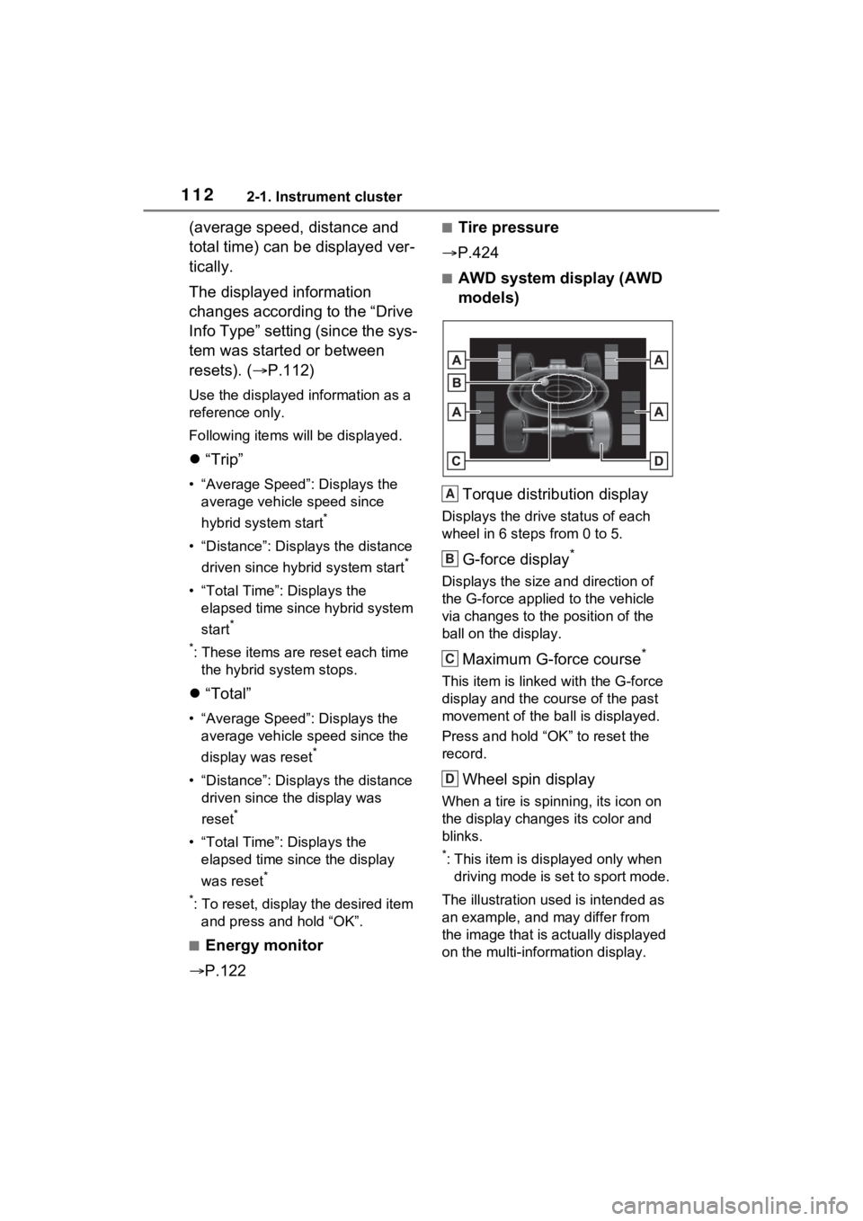
■AWD system display (AWD
models)
Torque distribution display
Displays the drive status of each
wheel in 6 steps from 0 to 5.
G-force display*
Displays the size a nd direction of
the G-force applied to the vehicle
via changes to the position of the
ball on the display.
Maximum G-force course*
This item is linke d with the G-force
display and the co urse of the past
movement of the ba ll is displayed.
Press and hold “OK” to reset the
record.
Wheel spin display
When a tire is spi nning, its icon on
the display changes its color and
blinks.
*: This item is displayed only when driving mode is set to sport mode.
The illustration used is intended as
an example, and may differ from
the image that is actually displayed
on the multi-information display.
A
B
C
D
Page 336 of 600

3354-5. Using the driving support systems
4
Driving
■VSC (Vehicle Stability Con-
trol)
Helps the driver to control skid-
ding when swerving suddenly or
turning on slippery road sur-
faces.
■Enhanced VSC (Enhanced
Vehicle Stability Control)
Provides cooperative control of
the ABS, TRAC, VSC and EPS.
Helps to maintai n directional
stability when swerving on slip-
pery road surfaces by con-
trolling steering performance.
■Trailer Sway Control
Helps the driver to control trailer
sway by selectively applying
brake pressure for individual
wheels and reducing driving
torque when trailer sway is
detected.
■TRAC (Traction Control)
Helps to maintain drive power
and prevent the drive wheels
from spinning when starting the
vehicle or accelerating on slip-
pery roads
■Active Cornering Assist
(ACA)
Helps to prevent the vehicle
from drifting to the outer side by
performing inner wheel brake
control when attempting to
accelerate while turning
■Hill-start assist control
Helps to reduce the backward movement of the vehicle when
starting on an uphill
■EPS (Electric Power Steer-
ing)
Employs an electric motor to
reduce the amount of effort
needed to turn the steering
wheel.
■E-Four (Electronic On-
Demand AWD system)
(AWD models)
Automatically controls the drive
system such as to front-wheel
drive or AWD (all wheel drive)
according to various running
conditions including normal driv-
ing, during cornering, on a
uphill, when starting off, during
acceleration, on a slippery roads
due to snow or rain, thus con-
tributing to stable operability and
driving stability.
■The Secondary Collision
Brake
When the SRS airbag sensor
detects a collision and the sys-
tem operates, the brakes and
brake lights are automatically
controlled to reduce the vehicle
speed and help reduce the pos-
sibility of further damage due to
a secondary collision.
■When the
TRAC/VSC/ABS/T railer Sway
Control systems are operating
The slip indicator light will flash
while the TRAC/VSC/ABS/Trailer
Sway Control systems are operat-
ing.
Page 492 of 600
4927-2. Steps to take in an emergency
first one loosened.
1Place the wheel lock key on
top of the wheel lock nut,
turning until the wheel lock
key and wheel lock nut pat-
terns engage.
2 Place the wheel nut wrench
on the wheel lock key, and
while applying pressure on
the wheel lock key, loosen
the wheel lock nut.
■Installation
For ease of installation, the
wheel lock nut should always be
the last one tightened.
1 By hand, install a wheel lock
nut on each wheel.
2 Place the wheel lock key on
top of the wheel lock nut,
turning until the wheel lock
key and wheel lock nut pat-
terns engage.
3 Place the wheel nut wrench
on the wheel lock key, and
while applying pressure on
the wheel lock key, tighten
the wheel lock nut to the rec-
ommended torque. 1
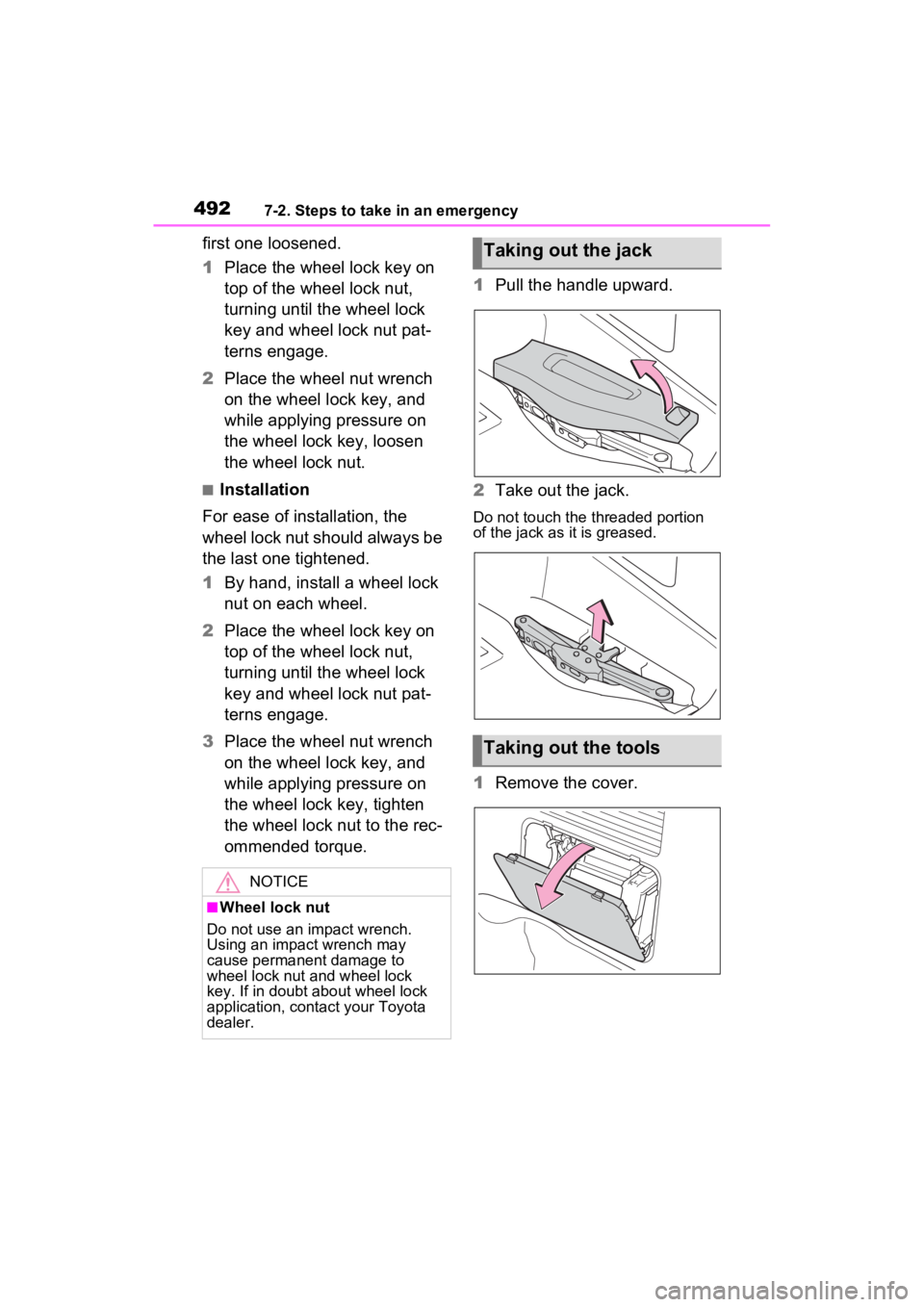
Pull the handle upward.
2 Take out the jack.
Do not touch the threaded portion
of the jack as it is greased.
1Remove the cover.
NOTICE
■Wheel lock nut
Do not use an impact wrench.
Using an impact wrench may
cause permanent damage to
wheel lock nut and wheel lock
key. If in doubt about wheel lock
application, contact your Toyota
dealer.
Taking out the jack
Taking out the tools
Page 495 of 600
4957-2. Steps to take in an emergency
7
When trouble arises
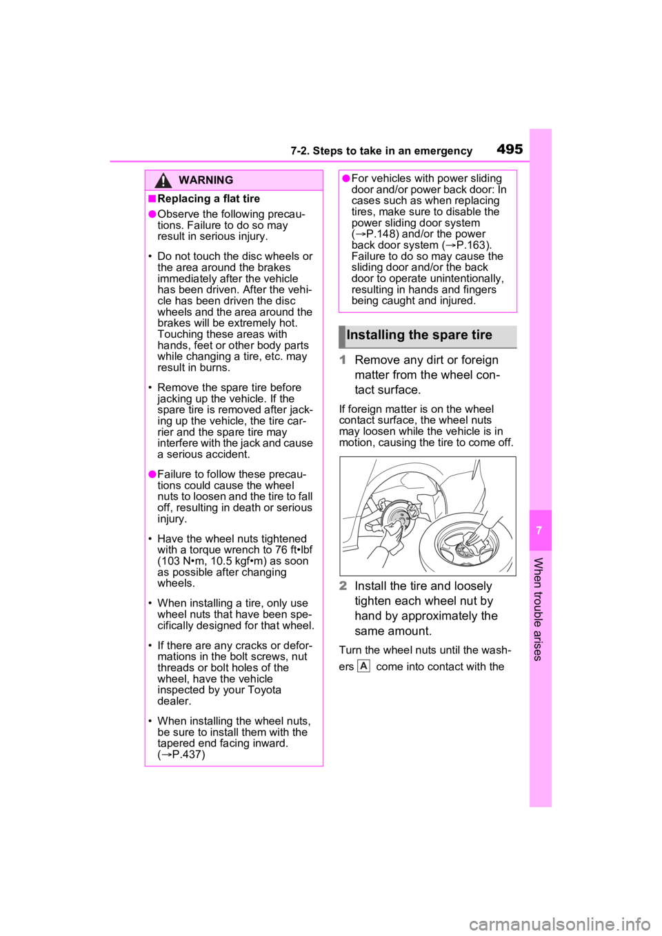
1Remove any dirt or foreign
matter from the wheel con-
tact surface.
If foreign matter is on the wheel
contact surface, the wheel nuts
may loosen while the vehicle is in
motion, causing the tire to come off.
2 Install the tire and loosely
tighten each wheel nut by
hand by approximately the
same amount.
Turn the wheel nuts until the wash-
ers come into contact with the
WARNING
■Replacing a flat tire
●Observe the following precau-
tions. Failure to do so may
result in serious injury.
• Do not touch the disc wheels or the area around the brakes
immediately after the vehicle
has been driven. After the vehi-
cle has been driven the disc
wheels and the area around the
brakes will be extremely hot.
Touching these areas with
hands, feet or other body parts
while changing a tire, etc. may
result in burns.
• Remove the spare tire before jacking up the v ehicle. If the
spare tire is removed after jack-
ing up the vehicle, the tire car-
rier and the spare tire may
interfere with the jack and cause
a serious accident.
●Failure to follow these precau-
tions could cause the wheel
nuts to loosen and the tire to fall
off, resulting in death or serious
injury.
• Have the wheel nuts tightened with a torque wrench to 76 ft•lbf
(103 N•m, 10.5 kgf•m) as soon
as possible after changing
wheels.
• When installing a tire, only use wheel nuts that have been spe-
cifically designed for that wheel.
• If there are any cracks or defor- mations in the bolt screws, nut
threads or bolt holes of the
wheel, have the vehicle
inspected by your Toyota
dealer.
• When installing the wheel nuts,
be sure to install them with the
tapered end facing inward.
( P.437)
●For vehicles with power sliding
door and/or power back door: In
cases such as wh en replacing
tires, make sure to disable the
power sliding door system
( P.148) and/or the power
back door system ( P.163).
Failure to do so may cause the
sliding door and/or the back
door to operate unintentionally,
resulting in hands and fingers
being caught and injured.
Installing the spare tire
A
Page 496 of 600
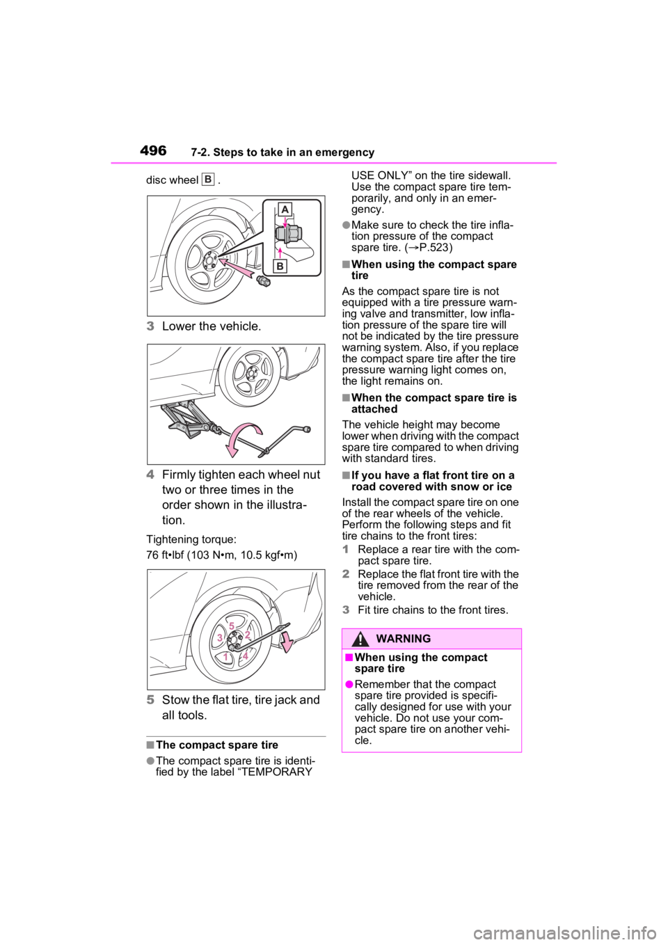
4967-2. Steps to take in an emergency
disc wheel .
3Lower the vehicle.
4 Firmly tighten each wheel nut
two or three times in the
order shown in the illustra-
tion.
Tightening torque:
76 ft•lbf (103 N•m, 10.5 kgf•m)
5Stow the flat tire, tire jack and
all tools.
■The compact spare tire
●The compact spare tire is identi-
fied by the label “TEMPORARY USE ONLY” on the tire sidewall.
Use the compact spare tire tem-
porarily, and only in an emer-
gency.
●Make sure to check the tire infla-
tion pressure of the compact
spare tire. (
P.523)
■When using the compact spare
tire
As the compact spare tire is not
equipped with a tire pressure warn-
ing valve and transm itter, low infla-
tion pressure of the spare tire will
not be indicated by the tire pressure
warning system. Also , if you replace
the compact spare ti re after the tire
pressure warning light comes on,
the light remains on.
■When the compact spare tire is
attached
The vehicle height may become
lower when driving with the compact
spare tire compared to when driving
with standard tires.
■If you have a flat front tire on a
road covered with snow or ice
Install the compact spare tire on one
of the rear wheels of the vehicle.
Perform the following steps and fit
tire chains to the front tires:
1 Replace a rear tire with the com-
pact spare tire.
2 Replace the flat front tire with the
tire removed from the rear of the
vehicle.
3 Fit tire chains to the front tires.
B
WARNING
■When using the compact
spare tire
●Remember that the compact
spare tire provided is specifi-
cally designed for use with your
vehicle. Do not use your com-
pact spare tire on another vehi-
cle.
Page 498 of 600
4987-2. Steps to take in an emergency
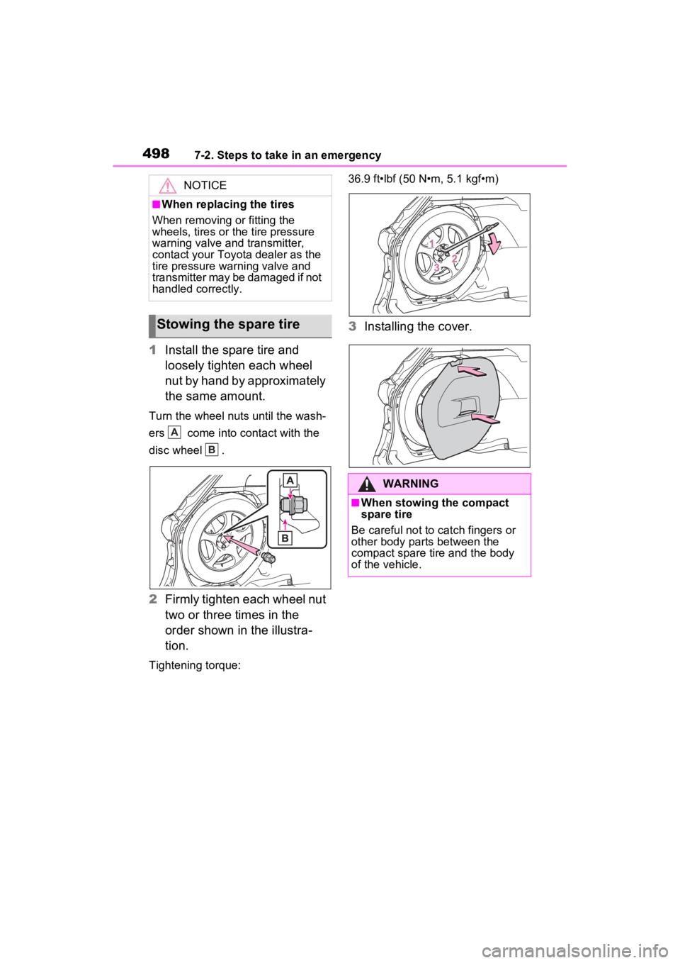
1Install the spare tire and
loosely tighten each wheel
nut by hand by approximately
the same amount.
Turn the wheel nuts until the wash-
ers come into contact with the
disc wheel .
2Firmly tighten each wheel nut
two or three times in the
order shown in the illustra-
tion.
Tightening torque: 36.9 ft•lbf (50 N•m, 5.1 kgf•m)
3
Installing the cover.
NOTICE
■When replacing the tires
When removing or fitting the
wheels, tires or the tire pressure
warning valve and transmitter,
contact your Toyota dealer as the
tire pressure warning valve and
transmitter may be damaged if not
handled correctly.
Stowing the spare tire
A
B
�:�$�5�1�,�1�*
■When stowing the compact
spare tire
Be careful not to catch fingers or
other body parts between the
compact spare tire and the body
of the vehicle.
Page 518 of 600
5188-1. Specifications
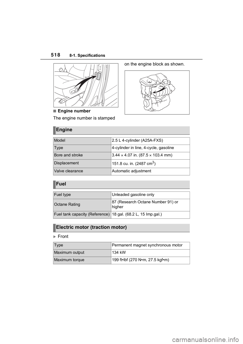
■Engine number
The engine number is stamped on the engine block as shown.
Front
Engine
Model2.5 L 4-cylinder (A25A-FXS)
Type4-cylinder in line
, 4-cycle, gasoline
Bore and stroke3.44 4.07 in. (87.5 103.4 mm)
Displacement151.8 cu. in. (2487 cm3)
Valve clearanceAutomatic adjustment
Fuel
Fuel typeUnleaded gasoline only
Octane Rating87 (Research Octane Number 91) or
higher
Fuel tank capacity (Reference)18 gal. (68.2 L, 15 Imp.gal.)
Electric motor (traction motor)
TypePermanent magnet synchronous motor
Maximum output134 kW
Maximum torque199 ft•lbf (270 N•m, 27.5 kgf•m)
Page 519 of 600

5198-1. Specifications
8
Vehicle specifications
Rear (AWD models)
■Oil capacity (Drain and refill
reference
*)
*: The engine oil capacity is a refer-
ence quantity to be used when
changing the engine oil. Warm up
the engine and turn off the hybrid
system, wait more than 5 min-
utes, and check the oil level on
the dipstick.
■Engine oil selection
“Toyota Genuine Motor Oil” is
used in your Toyota vehicle.
Use Toyota approved “Toyota
Genuine Motor Oil” or equiva-
lent to satisfy the following
grade and viscosity.
Oil grade: ILSAC GF-6B multigrade engine
oil
Recommended viscosity:
SAE 0W-16
SAE 0W-16 is the best choice
for good fuel economy and good
starting in cold weather.
If SAE 0W-16 is not available,
SAE 0W-20 oil may be used.
However, it must be replaced
with SAE 0W-16 at the next oil
change.
TypePermanent magnet synchronous motor
Maximum output40 kW
Maximum torque89.2 ft•lbf (121 N•m, 12.3 kgf•m)
Hybrid battery (traction battery)
TypeNickel-Metal hy
dride battery
Voltage7.2 V/module
Capacity6.5 Ah (3HR)
Quantity40 modules
Nominal voltage288 V
Lubrication system
With filter4.8 qt. (4.5 L, 4.0 Imp.
qt.)
Without fil-
ter4.4 qt. (4.2 L, 3.7 Imp.
qt.)