2022 TOYOTA SIENNA HYBRID warning
[x] Cancel search: warningPage 498 of 600
4987-2. Steps to take in an emergency
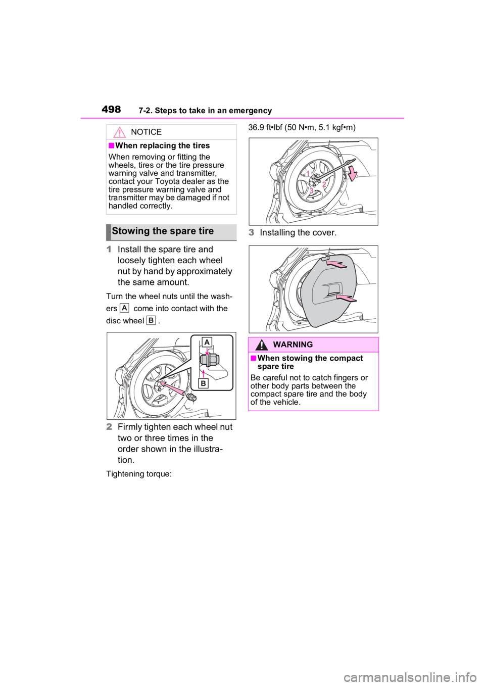
1Install the spare tire and
loosely tighten each wheel
nut by hand by approximately
the same amount.
Turn the wheel nuts until the wash-
ers come into contact with the
disc wheel .
2Firmly tighten each wheel nut
two or three times in the
order shown in the illustra-
tion.
Tightening torque: 36.9 ft•lbf (50 N•m, 5.1 kgf•m)
3
Installing the cover.
NOTICE
■When replacing the tires
When removing or fitting the
wheels, tires or the tire pressure
warning valve and transmitter,
contact your Toyota dealer as the
tire pressure warning valve and
transmitter may be damaged if not
handled correctly.
Stowing the spare tire
A
B
�:�$�5�1�,�1�*
■When stowing the compact
spare tire
Be careful not to catch fingers or
other body parts between the
compact spare tire and the body
of the vehicle.
Page 503 of 600
5037-2. Steps to take in an emergency
7
When trouble arises
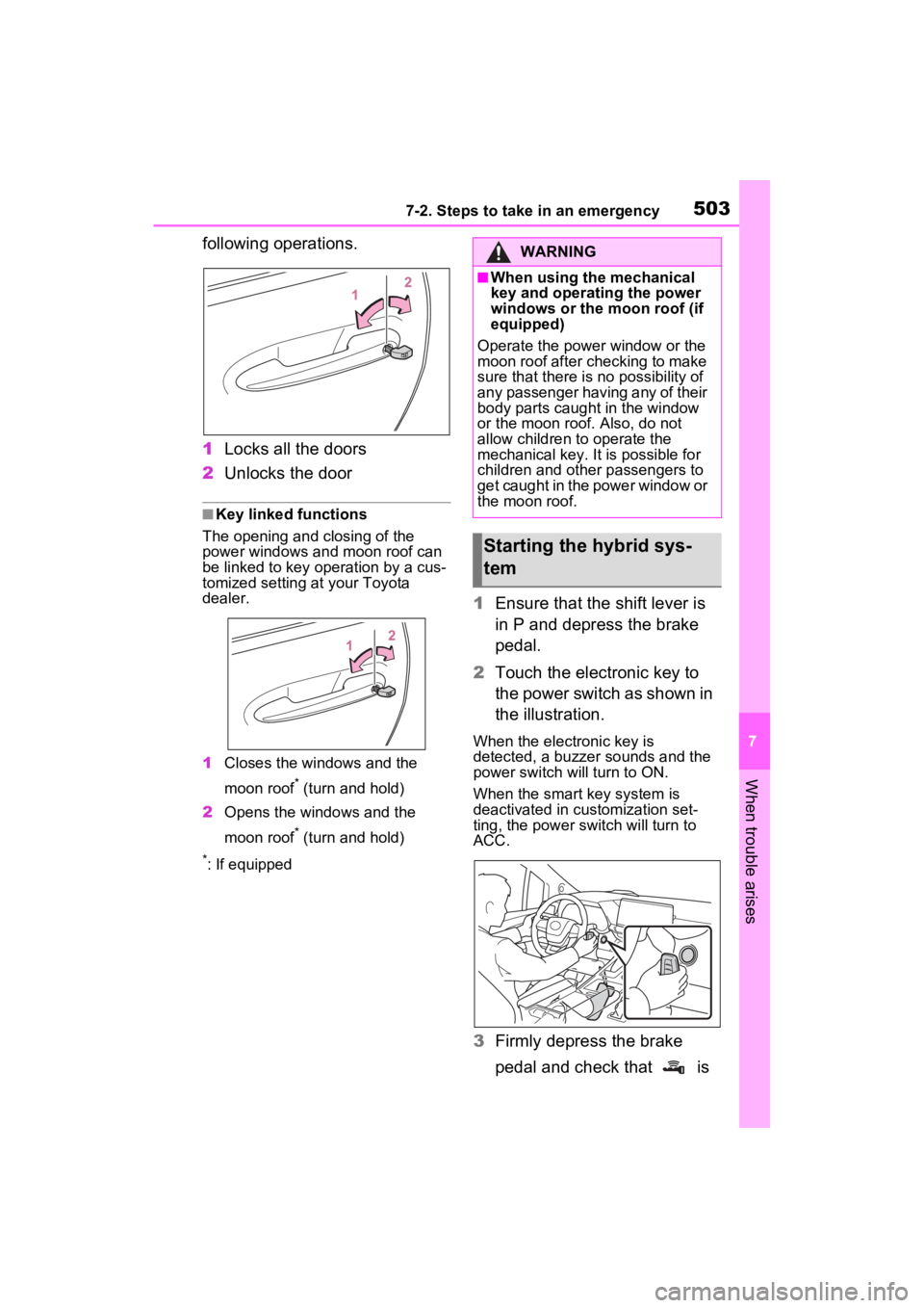
following operations.
1Locks all the doors
2 Unlocks the door
■Key linked functions
The opening and closing of the
power windows and moon roof can
be linked to key operation by a cus-
tomized setting at your Toyota
dealer.
1 Closes the windows and the
moon roof
* (turn and hold)
2 Opens the windows and the
moon roof
* (turn and hold)
*: If equipped
1Ensure that the shift lever is
in P and depress the brake
pedal.
2 Touch the electronic key to
the power switch as shown in
the illustration.
When the electronic key is
detected, a buzzer sounds and the
power switch will turn to ON.
When the smart key system is
deactivated in customization set-
ting, the power switch will turn to
ACC.
3Firmly depress the brake
pedal and check that is
WARNING
■When using the mechanical
key and operating the power
windows or the moon roof (if
equipped)
Operate the power window or the
moon roof after checking to make
sure that there is no possibility of
any passenger having any of their
body parts caught in the window
or the moon roof. Also, do not
allow children to operate the
mechanical key. It is possible for
children and other passengers to
get caught in the power window or
the moon roof.
Starting the hybrid sys-
tem
Page 507 of 600
5077-2. Steps to take in an emergency
7
When trouble arises
●The power switch mode is memo-
rized by the vehicle. When the 12-
volt battery is reconnected, the
system will return to the mode it
was in before the 12-volt battery
was discharged. Before discon-
necting the 12-volt battery, turn
the power switch off.
If you are unsure what mode the
power switch was in before the
12-volt battery discharged, be
especially careful when recon-
necting the 12-volt battery.
■When replacing the 12-volt bat-
tery
●Use a 12-volt battery that con-
forms to European regulations.
Use a battery that the case size is
same as the previous one (LN2),
20 hours rate capacity (20HR) is
equivalent (60Ah) or greater, and
performance rating (CCA) is
equivalent (563A) or greater.
• If the sizes differ, the 12-volt bat-
tery cannot be properly secured.
• If the 20 hour rate capacity is low,
even if the time period where the
vehicle is not used is a short time,
the 12-volt battery may discharge
and hybrid system may not be
able to start.
●Use a 12-volt battery with a han-
dle. If a 12-volt b attery without a
handle is used, removal is more
difficult.
●When removing the 12-volt bat-
tery: P.420
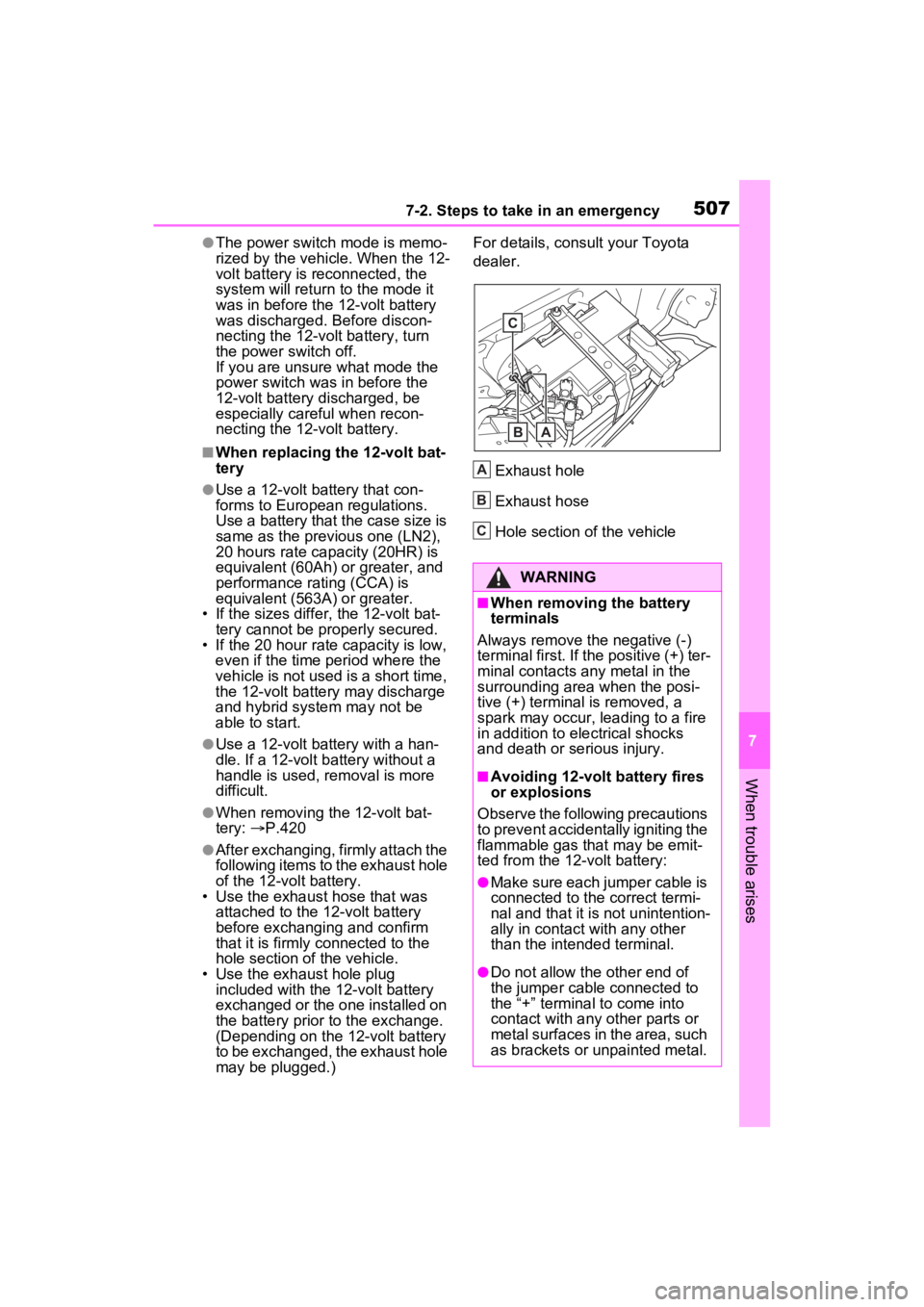
●After exchanging, firmly attach the
following items to the exhaust hole
of the 12-volt battery.
• Use the exhaust hose that was attached to the 12-volt battery
before exchangi ng and confirm
that it is firmly connected to the
hole section of the vehicle.
• Use the exhaust hole plug
included with the 12-volt battery
exchanged or the one installed on
the battery prior to the exchange.
(Depending on the 12-volt battery
to be exchanged, the exhaust hole
may be plugged.) For details, consu
lt your Toyota
dealer.
Exhaust hole
Exhaust hose
Hole section of the vehicle
WARNING
■When removing the battery
terminals
Always remove the negative (-)
terminal first. If the positive (+) ter-
minal contacts any metal in the
surrounding area when the posi-
tive (+) terminal is removed, a
spark may occur, leading to a fire
in addition to ele ctrical shocks
and death or serious injury.
■Avoiding 12-volt battery fires
or explosions
Observe the following precautions
to prevent accidentally igniting the
flammable gas that may be emit-
ted from the 12-volt battery:
●Make sure each jumper cable is
connected to the correct termi-
nal and that it is not unintention-
ally in contact with any other
than the intended terminal.
●Do not allow the other end of
the jumper cable connected to
the “+” terminal to come into
contact with any other parts or
metal surfaces in the area, such
as brackets or unpainted metal.
C
BA
A
B
C
Page 508 of 600
5087-2. Steps to take in an emergency
WARNING
●Do not allow the + and - clamps
of the jumper cables to come
into contact with each other.
●Do not smoke, use matches,
cigarette lighters or allow open
flame near the 12-volt battery.
■12-volt battery precautions
The 12-volt battery contains poi-
sonous and corrosi ve acidic elec-
trolyte, while related parts contain
lead and lead compounds.
Observe the following precautions
when handling the 12-volt battery:
●When working with the 12-volt
battery, always wear safety
glasses and take care not to
allow any battery fluids (acid) to
come into contact with skin,
clothing or the vehicle body.
●Do not lean over the 12-volt bat-
tery.
●In the event that battery fluid
comes into contact with the skin
or eyes, immediately wash the
affected area with water and
seek medical attention.
Place a wet sponge or cloth
over the affected area until
medical attention can be
received.
●Always wash your hands after
handling the 12-volt battery sup-
port, terminals, and other bat-
tery-related parts.
●Do not allow child ren near the
12-volt battery.
■After recharging the 12-volt
battery
Have the 12-volt battery
inspected at your Toyota dealer
as soon as possible.
If the 12-volt battery is deteriorat-
ing, continued use may cause the
12-volt battery to emit a malodor-
ous gas, which may be detrimen-
tal to the health of passengers.
■When replacing the 12-volt
battery
●For information regarding 12-
volt battery rep lacement, con-
tact your Toyota dealer.
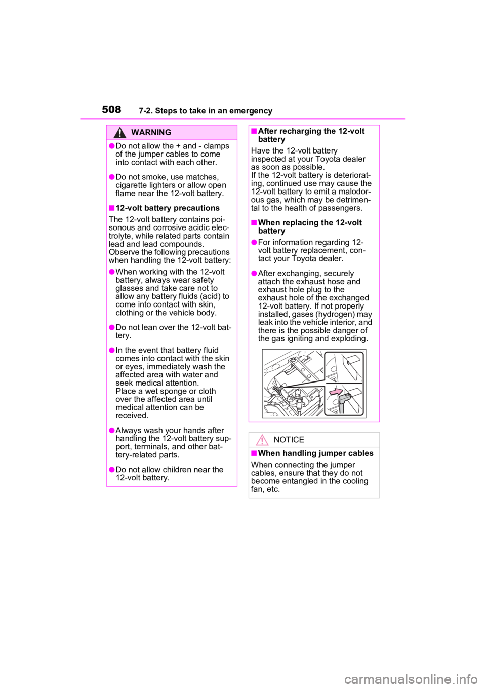
●After exchanging, securely
attach the exhaust hose and
exhaust hole plug to the
exhaust hole of the exchanged
12-volt battery. If not properly
installed, gases (hydrogen) may
leak into the vehicle interior, and
there is the po ssible danger of
the gas igniting and exploding.
NOTICE
■When handling jumper cables
When connecting the jumper
cables, ensure that they do not
become entangled in the cooling
fan, etc.
Page 512 of 600
5127-2. Steps to take in an emergency
Toyota dealer.
WARNING
■When inspecting under the
hood of your vehicle
Observe the following precau-
tions.
Failure to do so may result in seri-
ous injury such as burns.
●If steam is seen coming from
under the hood, do not open the
hood until the steam has sub-
sided. The engine compart-
ment may be very hot.
●After the hybrid system has
been turned off, check that the
“READY” indicator is off.
When the hybrid system is oper-
ating, the gasoline engine may
automatically start, or the cool-
ing fan may suddenly operate
even if the gasoline engine
stops. Do not touch or approach
rotating parts such as the fan,
which may lead to fingers or
clothing (especially a tie, a scarf
or a muffler) getting caught,
resulting in serious injury.
●Do not loosen the coolant reser-
voir cap while the hybrid system
and radiator are hot.
High temperature steam or
coolant could spray out.
NOTICE
■When adding engine/power
control unit coolant
Add coolant slowly after the
hybrid system has cooled down
sufficiently. Adding cool coolant to
a hot hybrid system too quickly
can cause damage to the hybrid
system.
■To prevent damage to the
cooling system
Observe the following precau-
tions:
●Avoid contaminating the coolant
with foreign matter (such as
sand or dust, etc.).
●Do not use any coolant additive.
Page 513 of 600
5137-2. Steps to take in an emergency
7
When trouble arises
1Stop the hybrid system. Set
the parking brake and shift
the shift lever to P.
2 Remove the mud, snow or
sand from around the stuck
tire.
3 Place wood, stones or some
other material to help provide
traction under the tires.
4 Restart the hybrid system
5 Shift the shift lever to D or R
and release the parking
brake. Then, while exercising
caution, depress the acceler-
ator pedal.
■When it is difficult to free the
vehicle
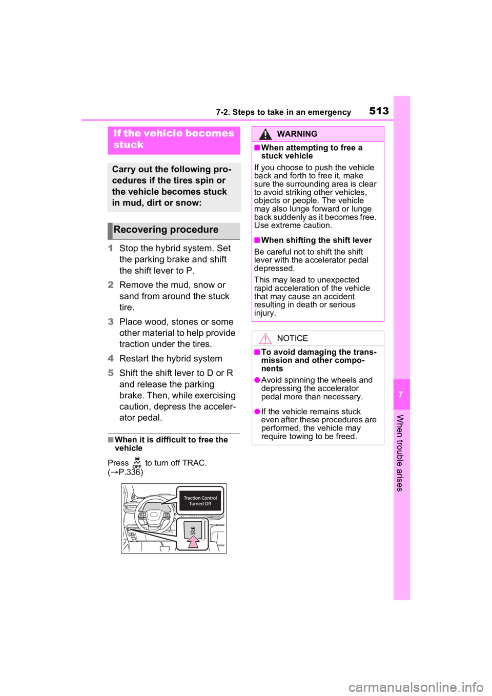
Press to turn off TRAC.
( P.336)
If the vehicle becomes
stuck
Carry out the following pro-
cedures if the tires spin or
the vehicle becomes stuck
in mud, dirt or snow:
Recovering procedure
WARNING
■When attempting to free a
stuck vehicle
If you choose to push the vehicle
back and forth to free it, make
sure the surrounding area is clear
to avoid striking other vehicles,
objects or people. The vehicle
may also lunge forward or lunge
back suddenly as it becomes free.
Use extreme caution.
■When shifting the shift lever
Be careful not to shift the shift
lever with the accelerator pedal
depressed.
This may lead to unexpected
rapid acceleration of the vehicle
that may cause an accident
resulting in dea th or serious
injury.
NOTICE
■To avoid damaging the trans-
mission and other compo-
nents
●Avoid spinning the wheels and
depressing the accelerator
pedal more than necessary.
●If the vehicle remains stuck
even after these procedures are
performed, the vehicle may
require towing to be freed.
Page 522 of 600
5228-1. Specifications
*1: Minimum pedal clearance when depressed with a force of 67.4 lbf (300
N, 30.6 kgf) while the hyb rid system is operating.
*2: Make sure to confirm that the brake system warning light (yell ow) does
not illuminate. (If th e brake system warning light illuminates, refer to
P.464)
Brakes
Pedal clearance*14.17 in. (106 mm) Min.
Pedal free play0.04 0.24 in. (1.0 6.0 mm)
Brake pad wear limit0.04 in. (1.0 mm)
Parking brake indicator*2
When pulling the parking brake switch for
1 to 4 seconds: turns on
When pushing the parking brake switch for
1 to 4 seconds: turns off
Fluid typeFMVSS No.116 DOT 3 or SAE J1703
FMVSS No.116 DOT 4 or SAE J1704
Steering
Free playLess than 1.2 in. (30 mm)
Page 531 of 600
5318-1. Specifications
8
Vehicle specifications
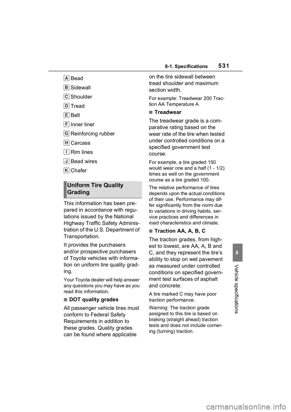
Bead
Sidewall
Shoulder
Tread
Belt
Inner liner
Reinforcing rubber
Carcass
Rim lines
Bead wires
Chafer
This information has been pre-
pared in accordance with regu-
lations issued by the National
Highway Traffic Safety Adminis-
tration of the U.S. Department of
Transportation.
It provides the purchasers
and/or prospective purchasers
of Toyota vehicles with informa-
tion on uniform tire quality grad-
ing.
Your Toyota dealer will help answer
any questions you may have as you
read this information.
■DOT quality grades
All passenger vehicle tires must
conform to Federal Safety
Requirements in addition to
these grades. Quality grades
can be found where applicable on the tire sidewall between
tread shoulder and maximum
section width.
For example: Treadwear 200 Trac-
tion AA Temperature A
■Treadwear
The treadwear grade is a com-
parative rating based on the
wear rate of the tire when tested
under controlled conditions on a
specified government test
course.
For example, a tire graded 150
would wear one and a half (1 - 1/2)
times as well on the government
course as a tire graded 100.
The relative performance of tires
depends upon the ac tual conditions
of their use. Performance may dif-
fer significantly from the norm due
to variations in dri ving habits, ser-
vice practices and differences in
road characteristics and climate.
■Traction AA, A, B, C
The traction grades, from high-
est to lowest, are AA, A, B and
C, and they represent the tire’s
ability to stop on wet pavement
as measured under controlled
conditions on specified govern-
ment test surfaces of asphalt
and concrete.
A tire marked C may have poor
traction performance.
Warning: The traction grade
assigned to this tire is based on
braking (straight ahead) traction
tests and does not include corner-
ing (turning) traction.
Uniform Tire Quality
Grading
A
B
C
D
E
F
G
H
I
J
K