2022 TOYOTA PROACE VERSO Disconnect
[x] Cancel search: DisconnectPage 208 of 360

208
Charging the traction
battery (Electric)
To recharge, connect the vehicle to a domestic electricity supply (domestic or accelerated charging) or to a fast public charger (superfast charging).For a full charge, follow the desired charging procedure without pausing it, until it ends
automatically. Charging can be either immediate or deferred (except fast public charger, mode 4).You can stop domestic or accelerated charging at any time by unlocking the vehicle and removing the nozzle. For superfast charging, refer to the fast public charger.For more information on the charging displays on the Instrument panel and the Touch screen, refer to the corresponding section.
NOTIC E
It is also possible to monitor the charging progress using the MyToyota application (Available soon).For more information on Remote functions, refer to the corresponding section.
NOTIC E
Lounge modeWhen the vehicle is connected, it is possible to switch on the ignition and use certain functions such as the audio and telematics system and the air conditioning system for several hours.
WARNI NG
As a safety measure, the engine will not start if the charging cable is plugged into the connector on the vehicle. A warning is displayed on the instrument panel.
NOTIC E
Cooling the traction batteryThe cooling fan in the engine compartment comes on during charging to cool the on-board charger and the traction battery.
NOTIC E
Vehicle immobilised for 1 to 12 monthsDischarge the traction battery down to 2 or 3 bars on the charge level indicator on the instrument panel.Do not connect the charging cable.
Always park the vehicle in a place with temperatures between -10°C and 30°C (parking in a place with extreme temperatures can damage the traction battery).Disconnect the cable from the (+) terminal of the accessory battery in the engine compartment.Connect a 12 V battery charger to the (+) and (-) terminals of the accessory battery about
every 3 months in order to recharge the accessory battery and maintain an operating voltage.
Precautions
Electric vehicles were developed in accordance with the guidelines on maximum electromagnetic fields issued by the International Commission on Non-Ionizing Radiation Protection (ICNIRP - 1998 Guidelines).
Wearers of pacemakers or equivalent devices
The electric vehicles have been developed in accordance with the guidelines on the maximum levels for electromagnetic fields issued by the International Commission on Non-Ionizing Radiation Protection (ICNIRP - 1998 Guidelines).
Page 211 of 360

2 11
Practical information
7
► Press OK.The setting is saved in the system.
Activation
NOTIC E
Deferred charging is only possible with modes 2 and 3.
► After programming the deferred charging, connect your vehicle to the desired charging equipment.
► Press this button in the flap within one minute to activate the system (confirmed by the
charging indicator lamp coming on in blue).
Disconnection
Before disconnecting the nozzle from the charging connector:
► If the vehicle is unlocked, lock it and then unlock it.► If the vehicle is locked, unlock it.The red indicator lamp in the flap goes out to confirm that the charging nozzle is unlocked.► In modes 2 and 3, remove the charging nozzle within 30 seconds.
NOTIC E
The locking of the nozzle is linked to the locking of the loading area. For more information on Total or selective unlocking, refer to the corresponding section.
The charging indicator lamp comes on in white.
NOTIC E
With selective door unlocking activated, press the unlocking button twice to disconnect the charging nozzle.
NOTIC E
When charging is complete, the green charging indicator lamp in the flap goes out after about 2 minutes.
Domestic charging, mode 2
The end of charging is confirmed when the green CHARGE indicator lamp on the control unit and
the green charging indicator lamp in the flap come on fixed.► Replace the protective cover on the charging nozzle and close the charging flap.► Disconnect the control unit end of the charging cable from the domestic socket.
Accelerated charging , mode 3
The end of charging is indicated by the charging control unit and by the fixed lighting of the green
indicator lamp in the flap.► Hang up the nozzle on the charging unit and close the charging flap.
Superfast charging, mode 4
The end of charging is indicated by the charger and by the fixed lighting of the green indicator lamp in the flap.► You can also pause charging by pressing this button in the flap (in mode 4 only).► Hang up the nozzle on the charger.► Depending on version, replace the protective cover on the lower section and close the charging flap.
NOTIC E
When the charging nozzle is disconnected, a message on the instrument panel indicates
that charging is complete, even if the charging nozzle was disconnected before full charging was completed.
Page 215 of 360

215
Practical information
7
Roof racks
NOTIC E
Max. authorised load weight:– Compact: 140 kg,– Medium and Long: 170 kg.
To fit a roof rack, use the fixing points provided for this purpose:► Place the roof rack on the roof aligned with the fixing points and secure each one to the roof in turn.► Ensure that the roof rack is correctly fitted (by shaking it).
Bonnet
WARNI NG
Stop & StartBefore doing anything under the bonnet, you must switch off the ignition to avoid any risk of injury resulting from an automatic change to START mode.
WARNI NG
Electric motorTake care with objects or clothing that could be caught in the blades of the cooling fan or in certain moving components - risk of strangulation and serious injury!Before carrying out any work under the bonnet, you must switch off the ignition, check that the READY indicator lamp is off on the instrument panel and disconnect the charging nozzle if it is plugged in.
NOTIC E
The location of the interior bonnet release lever prevents opening the bonnet when the left-hand front door is closed.
WARNI NG
When the engine is hot, handle the exterior safety catch and the bonnet stay with care (risk of burns), using the protected area.When the bonnet is open, take care not to damage the safety catch.Do not open the bonnet under very windy conditions.
WARNI NG
Cooling of the engine when stoppedThe engine cooling fan may start after the engine has been switched off.Take care with objects or clothing that could be caught in the blades of the fan!
Page 233 of 360

233
In the event of a breakdown
8
WARNI NG
The speed limit sticker must be secured to the interior of the vehicle in the driver's field of vision, to remind you that a wheel is in temporary use.
► Start the vehicle and leave the engine running.
NOTIC E
Do not start the compressor before connecting the white pipe to the tyre valve: the sealant product would be expelled through the pipe.
► Switch on the compressor by moving switch B to position I until the tyre pressure reaches 2.0 bars. The sealant product is injected under pressure into the tyre; do not disconnect the pipe from the valve during this operation (risk of blowback).
NOTIC E
If after approximately seven minutes this pressure is not reached, this indicates that the tyre is not repairable; contact any authorized Toyota retailer or Toyota authorized repairer, or any reliable repairer for assistance.
► Remove the kit and screw the cap back on
the white pipe. Take care to avoid contaminating
the vehicle with traces of fluid. Keep the kit to hand.
WARNI NG
Take care, the sealant product is harmful if swallowed and causes irritation to the eyes.Keep this product out of the reach of children.The use-by date of the fluid is marked on the bottle.After use, do not discard the bottle in standard waste, take it to any authorized Toyota retailer or Toyota authorized repairer, or any reliable repairer waste disposal site.Do not forget to obtain a new bottle of sealant, available from any authorized Toyota retailer or Toyota authorized repairer, or any reliable repairer.
► Drive immediately for approximately three miles (five kilometres), at reduced speed (between 12 and 37 mph (20 and 60 km/h)), to plug the puncture.
► Stop to check the repair and measure the tyre pressure using the kit.
Inflating, adjusting and
checking tyre pressures
► Turn selector A to the "Inflation" position.► Uncoil the white pipe G fully.► Connect the white pipe to the valve on the repaired tyre.► Reconnect the compressor's electric plug to the vehicle's 12 V socket.► Start the vehicle and leave the engine running.
Page 234 of 360

234
WARNI NG
Go to any authorized Toyota retailer or Toyota authorized repairer, or any reliable repairer as soon as possible.You must tell the technician that the kit has been used. After inspection, the technician will advise you on whether the tyre can be repaired or if it must be replaced.
► Adjust the tyre pressure using the compressor (to inflate: set switch B to position "I"; to deflate: set switch B to position "O" and press button C), according to the vehicle's tyre pressure label located by the driver's door.A subsequent loss of pressure indicates that the puncture has not been fully sealed; contact any authorized Toyota retailer or Toyota authorized repairer, or any reliable repairer to have your vehicle repaired.► Remove the kit and stow it.► Drive at reduced speed (50 mph (80 km/h) max.), limiting the distance travelled to approximately 125 miles (200 km).
NOTIC E
The compressor can also be used, without injecting sealant, to check and adjust the tyre pressures.
NOTIC E
If after approximately 7 minutes the required pressure is not reached, this indicates that the tyre is irreparably damaged; contact any authorized Toyota retailer or Toyota authorized repairer, or any reliable repairer for assistance.
WARNI NG
Do not drive more than 125 miles (200 km) with a repaired tyre; see any authorized Toyota retailer or Toyota authorized repairer, or any reliable repairer to have the tyre changed.
WARNI NG
Should the pressure of one or more tyres be adjusted, it is necessary to reinitialise the under-inflation detection system.For more information on Tyre under-inflation detection, refer to the corresponding section.
Removing the pipe and
cartridge
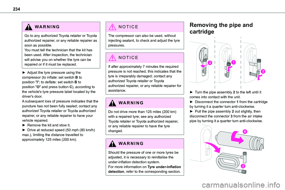
► Turn the pipe assembly 2 to the left until it comes into contact with the unit.► Disconnect the connector 1 from the cartridge by turning it a quarter turn anti-clockwise.► Pull the pipe assembly 2 out slightly, then disconnect the connector 3 from the air intake pipe by turning it a quarter turn anti-clockwise.
Page 242 of 360

242
Daytime running lamps/
sidelamps (LEDs)
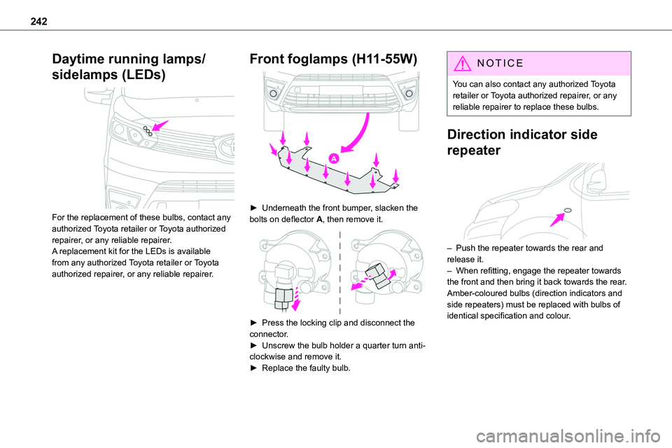
For the replacement of these bulbs, contact any authorized Toyota retailer or Toyota authorized repairer, or any reliable repairer.A replacement kit for the LEDs is available from any authorized Toyota retailer or Toyota authorized repairer, or any reliable repairer.
Front foglamps (H11-55W)
► Underneath the front bumper, slacken the bolts on deflector A, then remove it.
► Press the locking clip and disconnect the connector.► Unscrew the bulb holder a quarter turn anti-clockwise and remove it.► Replace the faulty bulb.
NOTIC E
You can also contact any authorized Toyota retailer or Toyota authorized repairer, or any reliable repairer to replace these bulbs.
Direction indicator side
repeater
– Push the repeater towards the rear and release it.– When refitting, engage the repeater towards the front and then bring it back towards the rear.Amber-coloured bulbs (direction indicators and side repeaters) must be replaced with bulbs of identical specification and colour.
Page 243 of 360

243
In the event of a breakdown
8
Rear lamps
1.Brake lamps/Sidelamps (P21/5W-21/5W)
2.Direction indicators (PY21W-21W amber)
3.Reversing lamps (P21W-21W)
4.Foglamps/Sidelamps (P21/4W-21/4W)
NOTIC E
For vehicles with interior trim, contact any authorized Toyota retailer or Toyota authorized repairer, or any reliable repairer to have the work done.
► Identify the defective lamp and then, depending on the version, open the rear doors or
the tailgate.
► With side-hinged doors, unscrew the 2 fixing screws from the outside.► With the tailgate, unclip the plastic trim from the outside and then tilt it outwards to remove it. Then unscrew the 2 fixing screws.
► From the inside, and depending on the version, remove the ventilation grille.► While holding the lamp in place, press the clip on the inside then carefully remove the lamp.► Disconnect the electrical connector.
► Spread the 3 lugs slightly, then extract the bulb holder.► Remove the faulty bulb by pressing lightly on it, then turning it a quarter turn clockwise.► Replace the bulb.
Third brake lamp (W5W - 5W)
► Depending on version, open the rear left-hand door or tailgate.
Page 244 of 360

244
► With side-hinged doors, remove the plastic cover with the aid of a screwdriver.► With a tailgate, unclip the trim at each end, rotating it from bottom to top, then unclip the centre clips to remove it.► Using a screwdriver through the aperture, push the lamp towards the outside.► Disconnect the electrical connector and then remove the lamp.► Unscrew the bulb holder a quarter turn anti-clockwise and replace the faulty bulb.To refit, press on the lamp to clip it into place.
Number plate lamps (W5W-W)
► Insert a thin screwdriver into one of the cut-outs on the exterior of the lens.► Push it outwards to unclip it.► Remove the lens and replace the faulty bulb.To refit, press the lens to clip it in.
Courtesy lamps (front and
rear)
LED courtesy lamps
For the replacement of these bulbs, contact any authorized Toyota retailer or Toyota authorized repairer, or any reliable repairer.A replacement kit for the LEDs is available from any authorized Toyota retailer or Toyota authorized repairer, or any reliable repairer.
Courtesy lamps with bulb
W5W-5W
► Unclip the lens by inserting a thin screwdriver into the slots at each side of the courtesy lamp.► Remove the bulb and change it.To refit, clip the lens in place and ensure that it is secure.