Page 12 of 320

12
Digital intrument panel
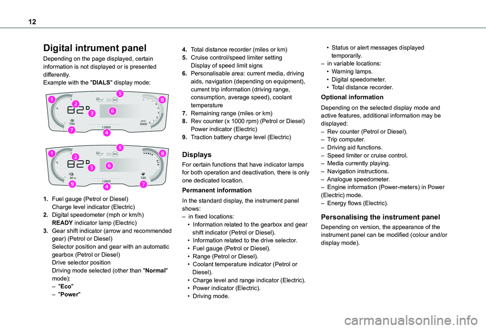
Depending on the page displayed, certain information is not displayed or is presented differently.Example with the "DIALS" display mode:
1.Fuel gauge (Petrol or Diesel)Charge level indicator (Electric)
2.Digital speedometer (mph or km/h)READY indicator lamp (Electric)
3.Gear shift indicator (arrow and recommended gear) (Petrol or Diesel)Selector position and gear with an automatic gearbox (Petrol or Diesel)Drive selector positionDriving mode selected (other than "Normal" mode):– "Eco"– "Power"
4.Total distance recorder (miles or km)
5.Cruise control/speed limiter settingDisplay of speed limit signs
6.Personalisable area: current media, driving aids, navigation (depending on equipment), current trip information (driving range, consumption, average speed), coolant temperature
7.Remaining range (miles or km)
8.Rev counter (x 1000 rpm) (Petrol or Diesel)Power indicator (Electric)
9.Traction battery charge level (Electric)
Displays
For certain functions that have indicator lamps for both operation and deactivation, there is only one dedicated location.
Permanent information
In the standard display, the instrument panel shows:– in fixed locations:• Information related to the gearbox and gear shift indicator (Petrol or Diesel).• Information related to the drive selector.• Fuel gauge (Petrol or Diesel).• Range (Petrol or Diesel).• Coolant temperature indicator (Petrol or Diesel).• Charge level and range indicator (Electric).• Power indicator (Electric).• Driving mode.
• Status or alert messages displayed temporarily.– in variable locations:• Warning lamps.• Digital speedometer.• Total distance recorder.
Optional information
Depending on the selected display mode and active features, additional information may be displayed:– Rev counter (Petrol or Diesel).– Trip computer.– Driving aid functions.– Speed limiter or cruise control.– Media currently playing.– Navigation instructions.– Analogue speedometer.– Engine information (Power-meters) in Power (Electric) mode.– Energy flows (Electric).
Personalising the instrument panel
Depending on version, the appearance of the instrument panel can be modified (colour and/or display mode).
Page 88 of 320

88
► Then set/save the activation time for each selection.► Press "OK" to confirm.
NOTIC E
You must allow at least 60 minutes between programming operations.
NOTIC E
Depending on the outside temperature, a certain amount of pre-conditioning time is necessary in order to reach the programmed temperature by the stored activation time.This pre-conditioning time lasts up to 45 min. with a Diesel engine and up to 30 min. with a petrol engine.
Long range remote control
(Depending on version.)This enables you to switch the heating in
the passenger compartment on or off from a distance.The remote control has a range of about 1 km (0.6 miles) in open country.
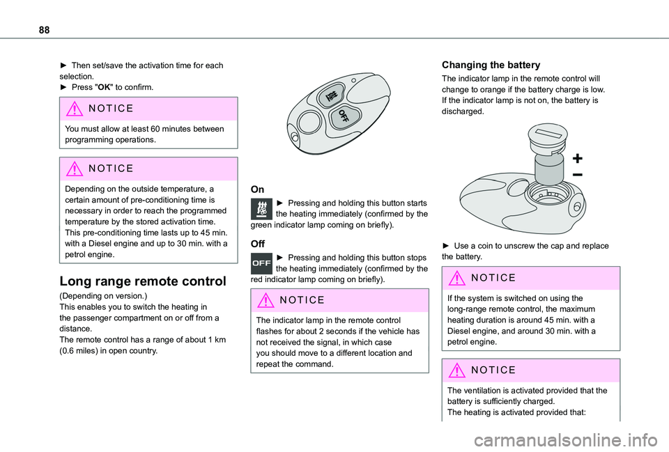
On
► Pressing and holding this button starts the heating immediately (confirmed by the green indicator lamp coming on briefly).
Off
► Pressing and holding this button stops the heating immediately (confirmed by the red indicator lamp coming on briefly).
NOTIC E
The indicator lamp in the remote control flashes for about 2 seconds if the vehicle has not received the signal, in which caseyou should move to a different location and repeat the command.
Changing the battery
The indicator lamp in the remote control will change to orange if the battery charge is low.If the indicator lamp is not on, the battery is discharged.
► Use a coin to unscrew the cap and replace the battery.
NOTIC E
If the system is switched on using the long-range remote control, the maximum
heating duration is around 45 min. with a Diesel engine, and around 30 min. with a petrol engine.
NOTIC E
The ventilation is activated provided that the battery is sufficiently charged. The heating is activated provided that:
Page 212 of 320

212
► Unclip the stay from its housing and place it in the support slot to hold the bonnet open.
Closing
► Hold the bonnet and pull out the stay from the support slot.► Clip the stay in its housing.► Lower the bonnet and release it near the end of its travel.► Pull on the bonnet to check that it is locked correctly.
WARNI NG
Because of the presence of electrical equipment under the bonnet, it is recommended that exposure to water (rain, washing, etc.) be limited.
Engine compartment
The engine represented is an example given for illustration purposes only.The locations of the following elements may vary:– Air filter.– Engine oil dipstick.– Engine oil filler cap.
Petrol engine
Diesel engine
1.Screenwash fluid reservoir
2.Engine coolant reservoir
3.Brake fluid reservoir
4.Battery / Fuses
5.Remote earth point (-)
6.Fusebox
7.Air filter
8.Engine oil filler cap
9.Engine oil dipstick
WARNI NG
Diesel fuel systemThis system is under very high pressure.All work must be carried out only by any authorized Toyota retailer or Toyota authorized repairer, or any reliable repairer.
Electric motor
1.Screenwash fluid reservoir
2.Engine coolant reservoir (level only)
3.Brake fluid reservoir
4.Battery/Fuses
5.Remote earth point (-)
6.Fusebox
7.400 V electrical circuit
8.Emergency circuit-breaker for emergency services and maintenance technicians