2022 TOYOTA MIRAI roof rack
[x] Cancel search: roof rackPage 36 of 556

361-1. For safe use
Owners Manual_USA_M62084_en
Front passenger occupant classification system (ECU and sen-
sors)
“AIRBAG ON” and “AIRBAG OFF” indicator lights
Your vehicle is equipped with ADVANCED AIRBAGS designed
based on the US motor vehicle safety standards (FMVSS208). The
airbag sensor assembly (ECU) cont rols airbag deployment based on
information obtained from the sensors etc. shown in the system
components diagram above. This in formation includes crash sever-
ity and occupant information. As the airbags deploy, a chemical
reaction in the inflators quickly fills the airbags with non-toxic gas to
help restrain the motion of the occupants.
■If the SRS airbags deploy
(inflate)
●Slight abrasions, burns, bruising,
etc., may be sustained from SRS
airbags, due to the extremely high
speed deployment (inflation) by
hot gases.
●A loud noise and white powder will
be emitted.
●Parts of the airbag module (steer-
ing wheel hub, airbag cover and
inflator) as well as the front seats,
parts of the front and rear pillars,
and roof side rails, may be hot for
several minutes. T he airbag itself
may also be hot.
●The windshield may crack.
●The fuel cell system will be
stopped and hydr ogen supply will
be stopped fro m the hydrogen
tank valves. ( P. 8 7 )
●All of the doors will be unlocked.
( P.122)
●The brakes and st op lights will be
controlled automatically. ( P.316)
●The interior lights will turn on auto-
matically. ( P.348)
●The emergency flashers will turn
on automatically. ( P.432)
●For Safety Connect subscribers, if
any of the following situations
occur, the system is designed to send an emergency call to the
response center, notifying them of
the vehicle’s location (without
needing to push the “SOS” button)
and an agent will attempt to speak
with the occupants to ascertain
the level of emergency and assis-
tance required. If the occupants
are unable to communicate, the
agent automatically treats the call
as an emergency and helps to dis-
patch the necessary emergency
services. (
P. 6 5 )
• An SRS airbag is deployed.
• A seat belt pretensioner is acti- vated.
• The vehicle is involved in a severe rear-end collision.
■SRS airbag deployment condi-
tions (SRS front airbags)
●The SRS front airbags will deploy
in the event of an impact that
exceeds the set threshold level
(the level of forc e corresponding
to an approximately 12 - 18 mph
[20 - 30 km/h] frontal collision with
a fixed wall that does not move or
deform).
However, this threshold velocity will
be considerably higher in the follow-
ing situations:
• If the vehicle strikes an object, such as a parked vehicle or sign
pole, which can move or deform
on impact
Page 39 of 556

391-1. For safe use
Owners Manual_USA_M62084_en
1
For safety and security
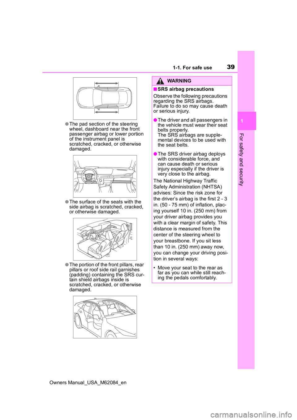
●The pad section of the steering
wheel, dashboard near the front
passenger airbag o r lower portion
of the instrument panel is
scratched, cracked, or otherwise
damaged.
●The surface of the seats with the
side airbag is scratched, cracked,
or otherwise damaged.
●The portion of the front pillars, rear
pillars or roof side rail garnishes
(padding) containing the SRS cur-
tain shield airbags inside is
scratched, cracked, or otherwise
damaged.
WARNING
■SRS airbag precautions
Observe the following precautions
regarding the SRS airbags.
Failure to do so may cause death
or serious injury.
●The driver and all passengers in
the vehicle must wear their seat
belts properly.
The SRS airbags are supple-
mental devices to be used with
the seat belts.
●The SRS driver airbag deploys
with considerable force, and
can cause death or serious
injury especially if the driver is
very close to the airbag.
The National Highway Traffic
Safety Administr ation (NHTSA)
advises: Since the risk zone for
the driver’s airbag is the first 2 - 3
in. (50 - 75 mm) of inflation, plac-
ing yourself 10 in. (250 mm) from
your driver airbag provides you
with a clear margin of safety. This
distance is measured from the
center of the steering wheel to
your breastbone. If you sit less
than 10 in. (250 mm) away now,
you can change you r driving posi-
tion in several ways:
• Move your seat to the rear as far as you can while still reach-
ing the pedals comfortably.
Page 42 of 556

421-1. For safe use
Owners Manual_USA_M62084_en
WARNING
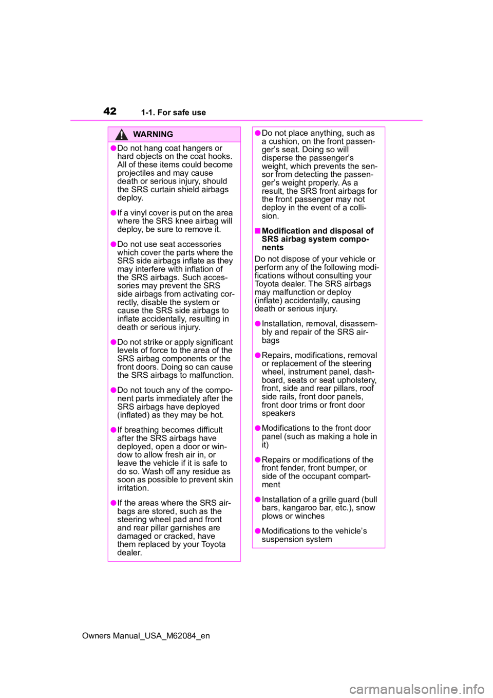
●Do not hang coat hangers or
hard objects on the coat hooks.
All of these items could become
projectiles and may cause
death or serious injury, should
the SRS curtain shield airbags
deploy.
●If a vinyl cover is put on the area
where the SRS knee airbag will
deploy, be sure to remove it.
●Do not use seat accessories
which cover the parts where the
SRS side airbags inflate as they
may interfere with inflation of
the SRS airbags. Such acces-
sories may prevent the SRS
side airbags from activating cor-
rectly, disable the system or
cause the SRS side airbags to
inflate accidentally, resulting in
death or serious injury.
●Do not strike or apply significant
levels of force to the area of the
SRS airbag components or the
front doors. Doing so can cause
the SRS airbags to malfunction.
●Do not touch any of the compo-
nent parts immediately after the
SRS airbags have deployed
(inflated) as they may be hot.
●If breathing becomes difficult
after the SRS airbags have
deployed, open a door or win-
dow to allow fresh air in, or
leave the vehicle if it is safe to
do so. Wash off any residue as
soon as possible to prevent skin
irritation.
●If the areas where the SRS air-
bags are stored, such as the
steering wheel pad and front
and rear pillar garnishes are
damaged or cracked, have
them replaced by your Toyota
dealer.
●Do not place anything, such as
a cushion, on the front passen-
ger’s seat. Doing so will
disperse the passenger’s
weight, which prevents the sen-
sor from detecting the passen-
ger’s weight properly. As a
result, the SRS front airbags for
the front passenger may not
deploy in the event of a colli-
sion.
■Modification and disposal of
SRS airbag system compo-
nents
Do not dispose of your vehicle or
perform any of the following modi-
fications without consulting your
Toyota dealer. The SRS airbags
may malfunction or deploy
(inflate) accidentally, causing
death or serious injury.
●Installation, re moval, disassem-
bly and repair of the SRS air-
bags
●Repairs, modific ations, removal
or replacement of the steering
wheel, instrument panel, dash-
board, seats or seat upholstery,
front, side and rear pillars, roof
side rails, front door panels,
front door trims or front door
speakers
●Modifications to the front door
panel (such as making a hole in
it)
●Repairs or modifications of the
front fender, front bumper, or
side of the occupant compart-
ment
●Installation of a grille guard (bull
bars, kangaroo bar, etc.), snow
plows or winches
●Modifications to the vehicle’s
suspension system
Page 90 of 556

902-1. Fuel cell vehicle
Owners Manual_USA_M62084_en
can help reduce excessive
fuel consumption.
In summer: When the ambient
temperature is high, use the
recirculated air mode. Doing
so will help to reduce the bur-
den on the air conditioning
system and reduce fuel con-
sumption as well.
In winter: Avoid excess heat-
ing. Use the seat heater (if
equipped) or steering heater
(if equipped) to minimize the
need for cabin heating
(P.342).
Using eco air conditioning
mode, this helps curb fuel
consumption even with the air
conditioning system turned
on. ( P.326, 334)
Make sure to check the tire infla-
tion pressure frequently.
Improper tire inflation pressure
can cause poor fuel economy.
Also, as snow tires can cause
large amounts of friction, their
use on dry roads can lead to
poor fuel economy. Use tires
that are appropriate for the sea-
son.
Carrying heavy luggage will lead
to reduced fuel economy. Install-
ing a large roof rack will also reduce fuel economy.
Checking tire inflation
pressure
Luggage
Page 209 of 556

2095-5. Using the driving support systems
Owners Manual_USA_M62084_en
5
Driving
■Certification
P.546
WARNING
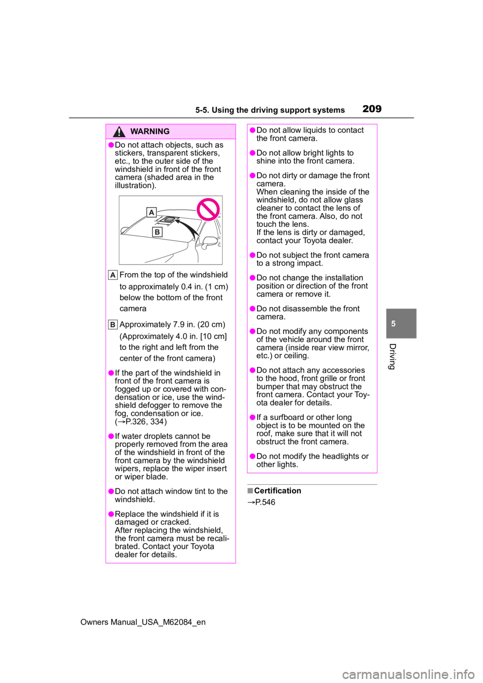
●Do not attach objects, such as
stickers, transparent stickers,
etc., to the oute r side of the
windshield in fr ont of the front
camera (shaded area in the
illustration).
From the top of the windshield
to approximately 0.4 in. (1 cm)
below the bottom of the front
camera
Approximately 7.9 in. (20 cm)
(Approximately 4.0 in. [10 cm]
to the right and left from the
center of the front camera)
●If the part of the windshield in
front of the front camera is
fogged up or covered with con-
densation or ice, use the wind-
shield defogger to remove the
fog, condensation or ice.
( P.326, 334)
●If water droplets cannot be
properly removed from the area
of the windshield in front of the
front camera by the windshield
wipers, replace the wiper insert
or wiper blade.
●Do not attach win dow tint to the
windshield.
●Replace the windshield if it is
damaged or cracked.
After replacing the windshield,
the front camera must be recali-
brated. Contact your Toyota
dealer for details.
●Do not allow liquids to contact
the front camera.
●Do not allow bright lights to
shine into the front camera.
●Do not dirty or damage the front
camera.
When cleaning the inside of the
windshield, do not allow glass
cleaner to contact the lens of
the front camera. Also, do not
touch the lens.
If the lens is dirty or damaged,
contact your Toyota dealer.
●Do not subject the front camera
to a strong impact.
●Do not change the installation
position or direction of the front
camera or remove it.
●Do not disassemble the front
camera.
●Do not modify any components
of the vehicle around the front
camera (inside rear view mirror,
etc.) or ceiling.
●Do not attach any accessories
to the hood, front grille or front
bumper that may obstruct the
front camera. Contact your Toy-
ota dealer for details.
●If a surfboard or other long
object is to be mounted on the
roof, make sure that it will not
obstruct the front camera.
●Do not modify the headlights or
other lights.
Page 493 of 556

4939-1. Specifications
Owners Manual_USA_M62084_en
9
Vehicle specifications
Production options weight
The combined weight of installed regular
production options weighing over 5 lb. (2.3
kg) in excess of the standard items which
they replace, not previously considered in
curb weight or accessory weight, including
heavy duty brakes, ride levelers, roof rack,
heavy duty 12-volt battery, and special trim
Rim
A metal support for a tire or a tire and tube
assembly upon which the tire beads are
seated
Rim diameter (Wheel diame-
ter)Nominal diameter o f the bead seat
Rim size designationRim diameter and width
Rim type designationThe industry manufacturer’s designation
for a rim by style or code
Rim widthNominal distance between rim flanges
Vehicle capacity weight (Total
load capacity)The rated cargo and luggage load plus 150
lb. (68 kg) times the vehicle’s designated
seating capacity
Vehicle maximum load on the
tire
The load on an individua l tire that is deter-
mined by distributing to each axle its share
of the maximum loaded vehicle weight,
and dividing by two
Vehicle normal load on the tire
The load on an individua l tire that is deter-
mined by distributing to each axle its share
of curb weight, accessory weight, and nor-
mal occupant weight (distributed in accor-
dance with Table 1
* below), and dividing by
two
Weather sideThe surface area of the rim not covered by
the inflated tire
Bead
The part of the tire that is made of steel
wires, wrapped or reinforced by ply cords
and that is shaped to fit the rim
Bead separationA breakdown of the bond between compo-
nents in the bead
Tire related termMeaning
Page 528 of 556

528Alphabetical Index
Owners Manual_USA_M62084_en
Average vehicle speed........... 104
B
Back-up lights Replacing light bulbs ............ 429
Battery (12-volt battery) ......... 400 Battery checking................... 400
If the 12-volt battery is dis-charged .............................. 471
Preparing and c hecking before
winter.................................. 320
Warning light ........................ 442
Battery (traction battery) ......... 79
Blind Spot Monitor (BSM) ...... 249 Enabling/disabling the system........................................... 251
Brake Brake hold ............................ 186
Fluid ............................. 399, 486
Parking brake ....................... 183
Warning light ........................ 441
Brake assist ............................ 315
Break-in tips ........ ................... 162
Brightness control Instrument panel light control . 98
BSM (Blind Spot Monitor) ...... 249 Enabling/disabling the system........................................... 251
Buzzer Hands off steering wheel warn-ing (LTA) ............................. 232
Vehicle sway warning function (LTA) ................................... 233
C
Care ................................. 380, 384 Aluminum wheel ornaments . 380
Aluminum wheels ................. 380
Exterior ................................. 380
Interior .................................. 384
Roof film ............................... 381 Seat belts .............................384
Traction battery air intake vent
...........................................420
Cargo and luggage .................167
Cargo capacity ........................170
Chains......................................321
Child restraint system ..............52 Fixed with a LATCH system ...60
Fixed with a seat belt..............56
Front passenger occupant clas-sification system ...................46
Points to remember ................52
Riding with children ................51
Types of child restraint system installation method ...............54
Using an anchor bracket ........62
Child safety ...............................51 12-volt battery precautions .401, 474
Airbag precautions .................39
Child restraint system .............54
Electronic sunshade .............356
Heated steering wheel and seat heater precautio ns..............342
How your child should wear the seat belt ................................30
Power window lock switch ....158
Power window precautions...157
Rear door child-protectors ....124
Removed electronic key battery precautions .........................424
Seat belt extender precautions .............................................30
Seat belt precautions..............51
Trunk precautions .................126
Child-protectors......................124
Cleaning ..........................380, 384 Aluminum wheel ornaments .380
Aluminum wheels .................380
Exterior .................................380
Interior ..................................384
Radar sensor ........................208