2022 RAM PROMASTER oil
[x] Cancel search: oilPage 5 of 268

3
INTERIOR STORAGE AND EQUIPMENT ............... 43 Storage..............................................................43
USB Control — If Equipped ..............................44
Power Outlets ...................................................45
Power Inverter — If Equipped...........................46
Auxiliary Switches — If Equipped .....................47
Wireless Charging Pad —
If Equipped .......................................................47
WINDOWS ............................................................. 48
Power Windows ...............................................48
Window Bar Grates — If Equipped...................49
Wind Buffeting .................................................49
HOOD....................................................................... 49
Opening .............................................................49
Closing...............................................................50
CARGO AREA FEATURES ...................................... 50
GETTING TO KNOW YOUR
INSTRUMENT PANEL
BASE / MIDLINE INSTRUMENT CLUSTER........... 51
Base / Midline Instrument Cluster
Descriptions ......................................................52
INSTRUMENT CLUSTER......................................... 53
Instrument Cluster Descriptions .....................54
INSTRUMENT CLUSTER DISPLAY ........................ 55
Location And Controls ......................................55
Change Engine Oil — If Equipped ....................56
Main Menu........................................................56
Vehicle Settings ................................................58 WARNING LIGHTS AND MESSAGES ....................59
Red Warning Lights ..........................................59
Yellow Warning Lights ......................................61
Yellow Indicator Lights .....................................65
Green Indicator Lights .....................................65
Blue Indicator Lights ........................................66
White Indicator Lights ......................................66
ONBOARD DIAGNOSTIC SYSTEM — OBD II ........ 67
Onboard Diagnostic System
(OBD II) Cybersecurity ......................................68
EMISSIONS INSPECTION AND MAINTENANCE
PROGRAMS.............................................................68
STARTING AND OPERATING
STARTING THE ENGINE ........................................69
Automatic Transmission ..................................69
Normal Starting ................................................69
Tip Start Feature .............................................69
Cold Weather Operation
(Below –22°F Or −30°C) ...............................69
Extended Park Starting ....................................69
If Engine Fails To Start .....................................70
After Starting ....................................................70
ENGINE BLOCK HEATER — IF EQUIPPED ...........70
ENGINE BREAK-IN RECOMMENDATIONS ..........70
PARKING BRAKE ....................................................71
Electric Park Brake (EPB) ................................71 AUTOMATIC TRANSMISSION .............................. 73
Ignition Park Interlock (Keyless Vehicle) ........ 74
Brake/Transmission Shift Interlock (BTSI)
System ............................................................. 74
9-Speed Automatic Transmission ................... 74
POWER STEERING ................................................ 78
ACTIVE SPEED LIMITER — IF EQUIPPED ............ 79
Activation .......................................................... 79
Exceeding The Set Speed ................................ 79
Deactivation ..................................................... 79
INTELLIGENT SPEED ASSIST (ISA) —
IF EQUIPPED ........................................................... 79
Activation .......................................................... 80
Exceeding The Set Speed ................................ 80
Deactivation ..................................................... 80
CRUISE CONTROL SYSTEMS — IF EQUIPPED ... 80
Cruise Control .................................................. 80
Adaptive Cruise Control (ACC) ......................... 82
TRAFFIC SIGN ASSIST SYSTEM —
IF EQUIPPED ........................................................... 91
Activation/Deactivation ................................... 91
Traffic Sign Assist Modes ................................ 91
Indications On The Display .............................. 91
ACTIVE DRIVING ASSIST SYSTEM —
IF EQUIPPED ........................................................... 92
Operation .......................................................... 92
Turning Active Driving Assist On Or Off ........... 93
Indications On The Display .............................. 94
22_VF_OM_EN_USC_t.book Page 3
Page 7 of 268

5
SAFETY TIPS ........................................................ 172 Transporting Passengers .............................. 172Transporting Pets ......................................... 173
Connected Vehicles....................................... 173
Safety Checks You Should Make Inside
The Vehicle ................................................... 173Periodic Safety Checks You Should Make
Outside The Vehicle ...................................... 174Exhaust Gas ................................................... 175Carbon Monoxide Warnings ......................... 175
IN CASE OF EMERGENCY
HAZARD WARNING FLASHERS ......................... 176
SOS AND ASSIST SYSTEM ................................. 176
JACKING AND TIRE CHANGING.......................... 180
Preparations For Jacking .............................. 180Jack Location — If Equipped ......................... 181Spare Tire Removal ....................................... 182
Jacking Instructions ...................................... 184Wheel Covers ................................................. 187
TIRE SERVICE KIT — IF EQUIPPED ..................... 187
Tire Service Kit Storage ................................ 187
Tire Service Kit Components And
Operation ....................................................... 187
Tire Service Kit Usage Precautions .............. 188
Sealing A Tire With Tire Service Kit .............. 189
JUMP STARTING................................................... 192
Preparations For Jump Start......................... 192Jump Starting Procedure .............................. 193Battery Location ............................................ 194 IF YOUR ENGINE OVERHEATS .......................... 194
GEAR SELECTOR OVERRIDE ............................. 195
FREEING A STUCK VEHICLE .............................. 196
TOWING A DISABLED VEHICLE ......................... 196 Automatic Transmission ............................... 197
ENHANCED ACCIDENT RESPONSE
SYSTEM (EARS) ................................................... 197
EVENT DATA RECORDER (EDR) ........................ 197
SERVICING AND MAINTENANCE
SCHEDULED SERVICING ................................... 198
Maintenance Plan ......................................... 199
ENGINE COMPARTMENT .................................... 202
3.6L Engine .................................................. 202
Checking Oil Level ......................................... 203
Adding Washer Fluid ..................................... 203
Maintenance-Free Battery ........................... 204Pressure Washing ......................................... 204
VEHICLE MAINTENANCE..................................... 204
Engine Oil ....................................................... 205
Engine Oil Filter ............................................. 205Engine Air Cleaner Filter .............................. 205Air Conditioner Maintenance ....................... 206
Body Lubrication ........................................... 207Windshield Wiper Blades ............................. 207
Exhaust System ............................................ 208
Cooling System .............................................. 209
Brake System ............................................... 211
Automatic Transmission ............................... 212 Fuses.............................................................. 213
Bulb Replacement ....................................... 220
TIRES .................................................................... 225
Tire Safety Information ................................ 225Tires — General Information ......................... 233
Tire Types....................................................... 236Spare Tires — If Equipped ............................ 237
Wheel And Wheel Trim Care ........................ 239Snow Traction Devices ................................. 240
Tire Rotation Recommendations ................. 241
DEPARTMENT OF TRANSPORTATION UNIFORM
TIRE QUALITY GRADES ...................................... 242
Treadwear...................................................... 242
Traction Grades ............................................. 242Temperature Grades..................................... 242
STORING THE VEHICLE ...................................... 243
BODYWORK .......................................................... 243
Protection From Atmospheric Agents .......... 243
Body And Underbody Maintenance ............. 243
Preserving The Bodywork ............................. 244
INTERIORS ........................................................... 244
Seats And Fabric Parts ................................. 244
Plastic And Coated Parts .............................. 245
Leather Surfaces........................................... 245
Glass Surfaces ............................................. 246Cleaning The Instrument Panel
Cupholders .................................................... 246
22_VF_OM_EN_USC_t.book Page 5
Page 11 of 268

9
SYMBOL GLOSSARY
Some car components have colored labels with symbols indicating
precautions to be observed when using this component. It is important to
follow all warnings when operating your vehicle. See below for the definition of
each symbol Úpage 59.
NOTE:Warning and Indicator lights are different based upon equipment options and
current vehicle status. Some telltales are optional and may not appear.
Red Warning Lights
Seat Belt Reminder Warning Light
Úpage 61
Air Bag Warning Light Úpage 59
Battery Charge Warning Light Úpage 60
Door Open Warning Light Úpage 60
Electronic Throttle Control (ETC) Warning Light Úpage 60
Transmission Fault Warning Light
Úpage 61
Engine Temperature Warning Light Úpage 60
Brake Warning Light Úpage 59
Oil Pressure Warning Light Úpage 61
Vehicle Security Warning Light Úpage 61
Electric Power Steering (EPS) Fault Warning Light Úpage 60
Hood Open Warning Light Úpage 60
Rear Cargo Door Warning Light Úpage 61
Red Warning Lights
1
22_VF_OM_EN_USC_t.book Page 9
Page 17 of 268

GETTING TO KNOW YOUR VEHICLE15
2. Separate the key fob halves using a #2 flat blade screwdriver or a coin, and gently pry the
two halves of the key fob apart. Make sure not
to damage the seal during removal.
Separating Case With A Coin
Key Fob Battery Replacement
3. Remove the back cover to access and replace
the battery. When replacing the battery, match
the (+) sign on the battery to the (+) sign on the
inside of the battery clip, located on the back
cover. Avoid touching the new battery with your
fingers. Skin oils may cause battery deterio -
ration. If you touch a battery, clean it with
rubbing alcohol.
4. To assemble the key fob case, snap the two halves together.
Programming And Requesting Additional
Key Fobs
Programming the key fob may be performed by an
authorized dealer.
NOTE:Once a key fob is programmed to a vehicle, it
cannot be repurposed and reprogrammed to
another vehicle.
Duplication of keys may be performed at an
authorized dealer. The VIN is required for
authorized dealer replacement of keys.
NOTE:Only keys that have been programmed to the
vehicle electronics can be used to start the vehicle.
Once a Sentry Key has been programmed to a
vehicle, it cannot be programmed to any other
vehicle. When having the Sentry Key Immobilizer
system serviced, bring all vehicle keys with you to
an authorized dealer.
WARNING!
The integrated key fob contains a coin cell
battery. Do not ingest the battery; there is a
chemical burn hazard. If the coin cell battery is
swallowed, it can cause severe internal burns
in just two hours and can lead to death.
If you think a battery may have been swal-
lowed or placed inside any part of the body,
seek immediate medical attention.
Keep new and used batteries away from chil -
dren. If the battery compartment does not
close securely, stop using the product and
keep it away from children.
WARNING!
Always remove the key fobs from the vehicle
and lock all doors when leaving the vehicle
unattended.
Always remember to place the ignition in the
OFF position.
2
22_VF_OM_EN_USC_t.book Page 15
Page 54 of 268

52GETTING TO KNOW YOUR INSTRUMENT PANEL
BASE / MIDLINE INSTRUMENT CLUSTER
D
ESCRIPTIONS
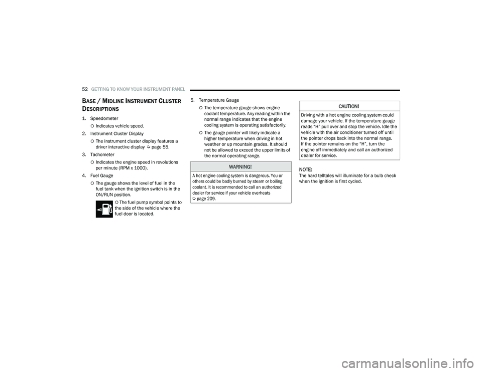
1. Speedometer
Indicates vehicle speed.
2. Instrument Cluster Display
The instrument cluster display features a
driver interactive display Ú page 55.
3. Tachometer
Indicates the engine speed in revolutions
per minute (RPM x 1000).
4. Fuel Gauge
The gauge shows the level of fuel in the
fuel tank when the ignition switch is in the
ON/RUN position.
The fuel pump symbol points to
the side of the vehicle where the
fuel door is located. 5. Temperature Gauge
The temperature gauge shows engine
coolant temperature. Any reading within the
normal range indicates that the engine
cooling system is operating satisfactorily.
The gauge pointer will likely indicate a
higher temperature when driving in hot
weather or up mountain grades. It should
not be allowed to exceed the upper limits of
the normal operating range.
NOTE:The hard telltales will illuminate for a bulb check
when the ignition is first cycled.
WARNING!
A hot engine cooling system is dangerous. You or
others could be badly burned by steam or boiling
coolant. It is recommended to call an authorized
dealer for service if your vehicle overheats
Ú
page 209.
CAUTION!
Driving with a hot engine cooling system could
damage your vehicle. If the temperature gauge
reads “H” pull over and stop the vehicle. Idle the
vehicle with the air conditioner turned off until
the pointer drops back into the normal range.
If the pointer remains on the “H”, turn the
engine off immediately and call an authorized
dealer for service.
22_VF_OM_EN_USC_t.book Page 52
Page 56 of 268

54GETTING TO KNOW YOUR INSTRUMENT PANEL
INSTRUMENT CLUSTER DESCRIPTIONS
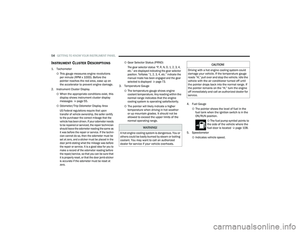
1. Tachometer
This gauge measures engine revolutions
per minute (RPM x 1000). Before the
pointer reaches the red area, ease up on
the accelerator to prevent engine damage.
2. Instrument Cluster Display
When the appropriate conditions exist, this
display shows instrument cluster display
messages Ú page 55.
Odometer/Trip Odometer Display Area
US Federal regulations require that upon
transfer of vehicle ownership, the seller certify
to the purchaser the correct mileage that the
vehicle has been driven. If your odometer needs
to be repaired or serviced, the repair technician
should leave the odometer reading the same as
it was before the repair or service. If the techni -
cian cannot do so, then the odometer must be
set at zero, and a sticker must be placed in the
door jamb stating what the mileage was before
the repair or service. It is a good idea for you to
make a record of the odometer reading before
the repair/service, so that you can be sure that
it is properly reset, or that the door jamb sticker
is accurate if the odometer must be reset at
zero.
Gear Selector Status (PRND)
The gear selector status “P, R, N, D, 1, 2, 3, 4,
etc.” are displayed indicating the gear selector
position. Telltales “1, 2, 3, 4, etc.” indicate the
manual mode has been engaged and the gear
selected is displayed
Ú
page 73.
3. Temperature Gauge
The temperature gauge shows engine
coolant temperature. Any reading within the
normal range indicates that the engine
cooling system is operating satisfactorily.
The pointer will likely indicate a higher
temperature when driving in hot weather
or up mountain grades. It should not be
allowed to exceed the upper limits of the
normal operating range. 4. Fuel GaugeThe pointer shows the level of fuel in the
fuel tank when the ignition switch is in the
ON/RUN position.
The fuel pump symbol points to
the side of the vehicle where the
fuel door is located Ú page 108.
5. Speedometer
Indicates vehicle speed.
WARNING!
A hot engine cooling system is dangerous. You or
others could be badly burned by steam or boiling
coolant. You may want to call an authorized
dealer for service if your vehicle overheats.
CAUTION!
Driving with a hot engine cooling system could
damage your vehicle. If the temperature gauge
reads “H,” pull over and stop the vehicle. Idle the
vehicle with the air conditioner turned off until
the pointer drops back into the normal range. If
the pointer remains on the “H,” turn the engine
off immediately and call an authorized dealer for
service.
22_VF_OM_EN_USC_t.book Page 54
Page 58 of 268

56GETTING TO KNOW YOUR INSTRUMENT PANEL
Right Arrow Button
Push and release the right arrow button to
access the information screens or submenu
screens of a main menu item.
Down Arrow Button
Push and release the down arrow button to
scroll downward through the main menu and
submenus.
OK Button
Push the OK button to access/select the infor -
mation screens or submenu screens of a main
menu item. Push and hold the OK button for
one second to reset displayed/selected
features that can be reset.
NOTE:For vehicles with a 3.5 inch instrument cluster
display, press the OK button to toggle between
mph or km/h.
For Screen Setup:
OK button allows user to enter menu and
submenus.
Within each submenu layer, the up and
down arrow buttons will allow the user to
select the item of interest.
Pushing the OK button makes the selection and
a confirmation screen will appear (returning the
user to the first page of the submenu).
Pushing the left arrow button will exit each
submenu layer and return to the main menu.
CHANGE ENGINE OIL — IF EQUIPPED
Your vehicle is equipped with an engine oil change
indicator system. The “Change Engine Oil” message
will display in the instrument cluster display. The
engine oil change indicator system is duty cycle
based, which means the engine oil change interval
may fluctuate, dependent upon your personal
driving style.
Unless reset, this message will continue to display
each time you turn the ignition switch to the
ON/RUN position. To turn off the message
temporarily, push and release the OK button.
To reset the oil change indicator system (after
performing the scheduled maintenance), refer
to the following procedure.
1. Turn the ignition switch to the ON position (do not start the engine).
2. Fully push the accelerator pedal slowly, three times, within 10 seconds.
3. Turn the ignition switch to the OFF position.
NOTE:If the indicator message illuminates when you start
the vehicle, the oil change indicator system did not
reset. If necessary, repeat this procedure.
MAIN MENU
NOTE:All of the following items are accessed by pressing
the OK button.
Home
Speedometer Graph
This uses the round bar graph filling to visually
represent current speed. When a speed control
system is active, the graph also provides visual
cues for the different states of that particular
speed control system.
Trip
Vehicles with 7 Inch Instrument Cluster Display
Access to trip information is available through the
following submenus.
Instant Consumption – Shows the instant
consumption in real time (MPG or L/100 km or
km/L).
Average Consumption – Shows the average
consumption (MPG or L/100 km or km/L) of
Trip A or Trip B since the last reset.
22_VF_OM_EN_USC_t.book Page 56
Page 59 of 268

GETTING TO KNOW YOUR INSTRUMENT PANEL57
Distance – Shows the total distance (mi or km)
traveled for Trip A or Trip B since the last reset.
Average Speed – Shows the average speed
(MPH or KM/H) of Trip A or Trip B since the last
reset.
Travel Time – Shows the total elapsed time of
travel since Trip A or Trip B has been reset.
Hold the OK button to reset feature information.
NOTE:During the reset the instruction line disappears
and a bar graph appears to indicate the resetting
status; when the bar graph is full the reset is
complete.
Vehicles with 3.5 Inch Instrument Cluster Display
Instant Information – Shows the instantaneous
consumption (MPG or L/100 km or km/L) and
distance to empty (mi or km).
Trip A – Shows the total distance (mi or km) trav -
eled, the total elapsed time of travel, average
consumption (MPG or L/100 km or km/L), and
the average speed (MPH or KM/H).
Trip B – Shows the total distance (mi or km) trav -
eled, the total elapsed time of travel, average
consumption (MPG or L/100 km or km/L), and
the average speed (MPH or KM/H).
Hold the OK button to reset feature information.
Driver Assist
The Driver Assist systems are electronic aids
designed to offer the driver help in certain driving
situations Ú page 79
Vehicle Info
Tire Pressure (TPMS)
TPMS shows the tire status with the numeric
pressure and the unit for each tire, when low
pressure is detected an alert mess and a yellow
telltale will pop-up in the instrument cluster display
Úpage 151.
Oil Temperature
A bar graph in your instrument cluster display will
show your current temperature of your oil.
Battery Voltage
A bar graph in your instrument cluster display will
show your current battery voltage.
Service Information – If Equipped
This feature can provide information on scheduled
maintenance. It will display either “Service
Distance” or “Service Days” Ú page 198.
Audio
Push and release the up or down arrow
button until the Audio Menu icon/title is
highlighted in the instrument cluster display. This menu will display the audio source
information, including the Song name, Artist name,
and audio source with an accompanying graphic.
Phone
This menu displays the current status of a phone
connected to the vehicle via Bluetooth®.
If no phone is connected, the menu will not
function when the
OK button is pushed. Otherwise,
if a phone is connected, push the OK button to
enter the menu. The following items will display:
Recent calls: displays a list of the last 10 calls.
SMS reader: displays the last 10 text messages
and if they are read or unread.
Favorite numbers: displays a maximum of
10 favorite numbers.
Navigation
If activated, this menu item will display navigation
status and directions.
Messages
This menu item allows you to display the
information messages/malfunction stored.
The background color of the display varies
according to the priorities of the failure:
Failed Messages with low priority display in yellow.
Failed Messages with high priority display in red.
3
22_VF_OM_EN_USC_t.book Page 57