2022 RAM 1500 upfitter
[x] Cancel search: upfitterPage 129 of 496

GETTING TO KNOW YOUR INSTRUMENT PANEL127
BATTERY SAVER ON/BATTERY SAVER
M
ODE MESSAGE — ELECTRICAL LOAD
R
EDUCTION ACTIONS — IF EQUIPPED
This vehicle is equipped with an Intelligent Battery
Sensor (IBS) to perform additional monitoring of
the electrical system and status of the vehicle
battery.
In cases when the IBS detects charging system
failure, or the vehicle battery conditions are
deteriorating, electrical load reduction actions will
take place to extend the driving time and distance
of the vehicle. This is done by reducing power to or
turning off non-essential electrical loads.
Load reduction is only active when the engine is
running. It will display a message if there is a risk
of battery depletion to the point where the vehicle
may stall due to lack of electrical supply, or will not
restart after the current drive cycle.
When load reduction is activated, the message
“Battery Saver On Some Systems May Have
Reduced Power” will appear in the instrument
cluster. These messages indicate the vehicle battery has a
low state of charge and continues to lose electrical
charge at a rate that the charging system cannot
sustain.NOTE:
The charging system is independent from load
reduction. The charging system performs a diag
-
nostic on the charging system continuously.
If the Battery Charge Warning Light is on it may
indicate a problem with the charging system
Ú page 129.
The electrical loads that may be switched off
(if equipped), and vehicle functions which can be
affected by load reduction:
Heated Seats / Vented Seats / Heated Wheel
Rear Defroster And Heated Mirrors
HVAC System
115 Volts AC Power Inverter System
Audio and Telematics System
Loss of the battery charge may indicate one or
more of the following conditions:
The charging system cannot deliver enough
electrical power to the vehicle system because
the electrical loads are larger than the capability
of charging system. The charging system is still
functioning properly.
Turning on all possible vehicle electrical loads
(e.g. HVAC to max settings, exterior and interior
lights, overloaded power outlets +12 Volts,
115 Volts AC, USB ports) during certain driving
conditions (city driving, towing, frequent stop -
ping).
Installing options like additional lights, upfitter
electrical accessories, audio systems, alarms
and similar devices.
Unusual driving cycles (short trips separated by
long parking periods).
The vehicle was parked for an extended period
of time (weeks, months).
The battery was recently replaced and was not
charged completely.
The battery was discharged by an electrical load
left on when the vehicle was parked.
The battery was used for an extended period
with the engine not running to supply radio,
lights, chargers, +12 Volt portable appliances
like vacuum cleaners, game consoles and
similar devices.
3
22_DT_OM_EN_USC_t.book Page 127
Page 130 of 496

128GETTING TO KNOW YOUR INSTRUMENT PANEL
What to do when an electrical load reduction
action message is present (“Battery Saver On” or
“Battery Saver Mode”)
During a trip:
Reduce power to unnecessary loads if possible:
Turn off redundant lights (interior or exte -
rior).
Check what may be plugged in to power
outlets +12 Volts, 115 Volts AC, USB ports.
Check HVAC settings (blower, temperature).
Check the audio settings (volume).
After a trip:
Check if any aftermarket equipment was
installed (additional lights, upfitter electrical
accessories, audio systems, alarms) and review
specifications if any (load and Ignition Off Draw
currents).
Evaluate the latest driving cycles (distance,
driving time and parking time).
The vehicle should have service performed if
the message is still present during consecutive
trips and the evaluation of the vehicle and
driving pattern did not help to identify the cause.
WARNING LIGHTS AND MESSAGES
The warning/indicator lights will illuminate in the
instrument panel together with a dedicated
message and/or acoustic signal when applicable.
These indications are indicative and precautionary
and as such must not be considered as exhaustive
and/or alternative to the information contained in
the Owner’s Manual, which you are advised to read
carefully in all cases. Always refer to the
information in this chapter in the event of a failure
indication. All active telltales will display first if
applicable. The system check menu may appear
different based upon equipment options and
current vehicle status. Some telltales are optional
and may not appear.
RED WARNING LIGHTS
Air Bag Warning Light
This warning light will illuminate to
indicate a fault with the air bag, and will
turn on for four to eight seconds as a bulb
check when the ignition is placed in the
ON/RUN or ACC/ON/RUN position. This light will
illuminate with a single chime when a fault with the
air bag has been detected, it will stay on until the
fault is cleared. If the light is either not on during
startup, stays on, or turns on while driving, have
the system inspected at an authorized dealer as
soon as possible.
Brake Warning Light
This warning light monitors various brake
functions, including brake fluid level and
parking brake application. If the brake
light turns on it may indicate that the
parking brake is applied, that the brake fluid level
is low, or that there is a problem with the Anti-Lock
Brake System reservoir.
If the light remains on when the parking brake has
been disengaged, and the fluid level is at the full
mark on the master cylinder reservoir, it indicates
a possible brake hydraulic system malfunction or
that a problem with the Brake Booster has been
detected by the Anti-Lock Brake System (ABS) /
Electronic Stability Control (ESC) system. In this
case, the light will remain on until the condition has
been corrected. If the problem is related to the
brake booster, the ABS pump will run when
applying the brake, and a brake pedal pulsation
may be felt during each stop.
The dual brake system provides a reserve braking
capacity in the event of a failure to a portion of the
hydraulic system. A leak in either half of the dual
brake system is indicated by the Brake Warning
Light, which will turn on when the brake fluid level
in the master cylinder has dropped below a
specified level.
The light will remain on until the cause is corrected.
22_DT_OM_EN_USC_t.book Page 128
Page 432 of 496

430SERVICING AND MAINTENANCE
F05 ––Spare
F06 –10 Amp Red OUTPUT TO UPFITTER PDC *
F07 ––Spare
F08 20 Amp Blue –Trailer Tow Backup
F09 –20 Amp Yellow Trailer Stop / Turn Lamp Left
F10 –20 Amp Yellow Trailer Stop / Turn Lamp Right
F11 –15 Amp Blue ID/CLEARANCE LIGHTS *
F12 20 Amp Blue –Trailer Tow Park Lamp
F13 ––Spare
F14 –10 Amp Red AC Clutch
F15 –5 Amp Tan Intelligent Battery Sensor (IBS)
F16 ––Spare *
F17 –20 Amp Yellow Air Suspension
F18 –15 Amp Blue AGS / Rear Axle Cooling Valve / Active Air Dam
F19 ––Spare
F20 –20 Amp Yellow Adjustable Pedals *
F21 30 Amp Pink –Power Side Step *
F22 50 Amp Red –Air Module *
F23 ––Spare
F24 –20 Amp Yellow TCM SBW
Cavity Cartridge Fuse Micro Fuse Description
* If Equipped
22_DT_OM_EN_USC_t.book Page 430
Page 439 of 496
SERVICING AND MAINTENANCE437
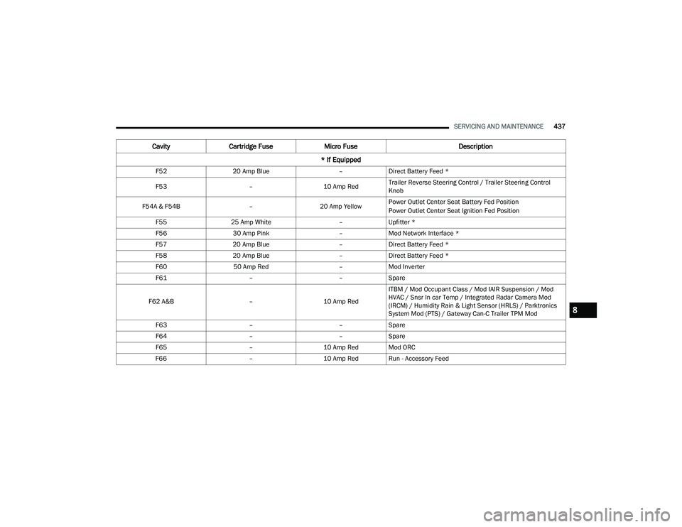
F52 20 Amp Blue –Direct Battery Feed *
F53 –10 Amp RedTrailer Reverse Steering Control / Trailer Steering Control
Knob
F54A & F54B –20 Amp YellowPower Outlet Center Seat Battery Fed Position
Power Outlet Center Seat Ignition Fed Position
F55 25 Amp White –Upfitter *
F56 30 Amp Pink –Mod Network Interface *
F57 20 Amp Blue –Direct Battery Feed *
F58 20 Amp Blue –Direct Battery Feed *
F60 50 Amp Red –Mod Inverter
F61 ––Spare
F62 A&B –10 Amp RedITBM / Mod Occupant Class / Mod IAIR Suspension / Mod
HVAC / Snsr In car Temp / Integrated Radar Camera Mod
(IRCM) / Humidity Rain & Light Sensor (HRLS) / Parktronics
System Mod (PTS) / Gateway Can-C Trailer TPM Mod
F63 ––Spare
F64 ––Spare
F65 –10 Amp Red Mod ORC
F66 –10 Amp Red Run - Accessory Feed
CavityCartridge Fuse Micro Fuse Description
* If Equipped
8
22_DT_OM_EN_USC_t.book Page 437