2022 PEUGEOT 3008 spare wheel
[x] Cancel search: spare wheelPage 179 of 292
177
Practical information
7These points are concealed by the vehicle doors
when the doors are closed.
The roof bar fixings have a stud which must be
inserted into the opening of each fixing point.
Maximum load distributed over the
transverse roof bars, for a loading height
not exceeding 40 cm (except bicycle carrier):
80
kg.
As this value may change, please verify the
maximum load quoted in the guide supplied
with the roof bars.
If the height exceeds 40 cm, adapt the speed
of the vehicle to the profile of the road to
avoid damaging the roof bars and the fixings
on the vehicle.
Be sure to refer to national legislation in order
to comply with the regulations for transporting
objects that are longer than the vehicle.
Recommendations
Distribute the load uniformly, taking care
to avoid overloading one of the sides.
Arrange the heaviest part of the load as close
as possible to the roof.
Secure the load firmly.
Drive gently: the vehicle will be more
susceptible to the effects of side winds and its
stability may be affected.
Regularly check the security and tight
fastening of the roof bars, at least before each
trip.
Remove the roof bars once they are no longer
needed.
Sunroof
Check that the load does not pass below
the roof bars so that it does not impede the
movements of the sunroof - risk of major
damage!
Snow chains
In wintry conditions, snow chains improve
traction as well as the behaviour of the vehicle
when braking.
Snow chains must be fitted only to the
front wheels. They must never be fitted to
"space-saver" type spare wheels.
Observe the legislation in force in your
country relating to the use of snow
chains and maximum authorised speeds.
Use only chains designed to be fitted to the type
of wheel fitted to the vehicle:
Original tyre size Maximum link size 215/65 R17 9 mm
225/55 R18 9 mm
205/55 R19 9 mm
Original tyre size Maximum link size
235/50 R19 Not suitable for
chains
For more information on snow chains, contact a
PEUGEOT dealer or a qualified workshop.
Installation tips
► To fit the snow chains during a journey, stop
the vehicle on a flat surface at the side of the
road.
►
Apply the parking brake and position any
wheel chocks under the wheels to prevent
movement of the vehicle.
►
Fit the snow chains following the instructions
provided by the manufacturer
.
►
Move off gently and drive for a few moments,
without exceeding 31
mph (50 km/h).
►
Stop the vehicle and check that the snow
chains are correctly tightened.
It is strongly recommended that you
practise fitting the snow chains on a level
and dry surface before setting off.
Avoid driving with snow chains on roads that have been cleared of snow to avoid
damaging the vehicle's tyres and the road
surface. If the vehicle is fitted with alloy
wheels, check that no part of the chain or its
fixings is in contact with the wheel rim.
Page 186 of 292
184
Practical information
checked by a PEUGEOT dealer or a qualified
workshop.
For more information on the Electric
parking brake, refer to the
corresponding section.
Brake pads
Brake wear depends on the style of
driving, particularly in the case of vehicles
used in town, over short distances. It may be
necessary to have the condition of the brakes
checked, even between vehicle services.
Unless there is a leak in the circuit, a drop in the
brake fluid level indicates that the brake pads
are worn.
After washing the vehicle, moisture, or in wintry conditions, ice can form on the
brake discs and pads: braking efficiency may
be reduced. Gently dab the brakes to dry and
defrost them.
Brake disc wear
For information on checking brake disc
wear, contact a PEUGEOT dealer or a
qualified workshop.
Wheels and tyres
The inflation pressure of all tyres, including the spare wheel, must be
checked on "cold” tyres.
The pressures indicated on the tyre pressure
label are valid for "cold" tyres. If you have driven
for more than 10 minutes or more than 6 miles
(10 kilometres) at over 31 mph (50
km/h), add
0.3 bar (30 kPa) to the values indicated on the
label.
Under-inflation increases energy
consumption. Non-compliant tyre
pressures cause tyres to wear prematurely
and have an adverse effect on the vehicle's
road holding - risk of accident!
Driving with worn or damaged tyres reduces the
braking and road holding performance of the
vehicle. Regularly check the condition of the
tyres (tread and sidewalls) and rims as well as
the presence of the valve caps.
When the wear indicators no longer appear set
back from the tread, the depth of the grooves is
less than 1.6 mm; replace the tyres as soon as
possible.
Using different size wheels and tyres from those
specified can affect the lifetime of tyres, wheel
rotation, ground clearance, the speedometer
reading and have an adverse effect on road
holding.
Fitting different tyres on the front and rear axles
can cause the ESC to mistime.
Always mark the direction of rotation on the tyres
that will be stored when fitting winter or summer
tyres. Store them in a cool, dry place and away
from direct exposure to the sun's rays.
Winter or 4-seasons tyres can be
identified by this symbol on their
sidewalls.
Shock absorbers
It is not easy for drivers to detect when
shock absorbers are worn. Nevertheless,
the shock absorbers have a major impact on
road holding and braking performance.
For your safety and driving comfort, it is
important to have them regularly checked by a
PEUGEOT dealer or a qualified workshop.
Timing and accessory kits
The timing and accessory kits are used
from the time the engine is started until it
is switched off. It is normal for them to wear over
time.
A
faulty timing or accessory kit can damage
the engine, rendering it unusable. Observe the
recommended replacement frequency, stated in
distance travelled or time elapsed, whichever is
reached first.
AdBlue® (BlueHDi)
To respect the environment and ensure compliance with the Euro 6 standard, without
adversely affecting the performance or fuel
consumption of its Diesel engines, PEUGEOT
has taken the decision to equip its vehicles with
a system that combines SCR (Selective Catalytic
Reduction) with a Diesel Particle Filter (DPF) for
the treatment of exhaust gases.
SCR system
Using a liquid called AdBlue® that contains
urea, a catalytic converter turns up to 85% of
the nitrogen oxides (NOx) into nitrogen and
water, which are harmless to health and the
environment.
The AdBlue® is contained in a special
tank holding about 17 litres.
Its capacity allows a driving range of
approximately 4,000 miles (6,500 km), which
may vary considerably depending on your
driving style.
An alert system is triggered once the reserve
level is reached: it is then possible to drive for a
further 1,500 miles (2,400 km) before the tank is
empty and the vehicle is immobilised.
For more information on the Warning
and indicator lamps and the associated
alerts, or the Indicators, please refer to the
corresponding sections.
Once the AdBlue® tank is empty, a device
required by law prevents the engine from
being restarted.
If the SCR system is faulty, the level of
emissions from the vehicle will no longer meet
the Euro 6 standard and the vehicle starts
polluting the environment.
Page 192 of 292

190
In the event of a breakdown
Accessing the tools
Some of the tools are stored beneath the floor
against the boot sill.
The left-hand box contains the wheelbrace and
its extension piece.
The right-hand box contains the wheel chocks
and the towing eye.
To access it:
► Open the boot.
► Fold the concertina panels.
► Install the third row seats.
► Unclip the required tools from the boot sill
trim.
2.0 HDi engines
► Open the bonnet and then, if necessary ,
unclip the cover to access the priming pump.
►
Loosen the degassing bolt.
► Operate the priming pump until fuel
appears in the transparent tube.
►
Retighten the degassing bolt.
►
Operate the starter motor until the engine
starts (if the engine does not start at the first
attempt, wait around 15
seconds before trying
again).
►
If the engine does not start after a few
attempts, operate the priming pump again, then
the starter motor
.
►
Put the cover back in place and clip it in, then
close the bonnet.
Tool kit
Set of tools supplied with the vehicle.
Its content depends on your vehicle's equipment:
–
T
emporary puncture repair kit.
–
Spare wheel.
Accessing the tools
The tool kit is stored in the boot, under the floor.
To access it:
Versions with 2-position boot floor:
►
Open the boot.
►
Place the adjustable boot floor in the high
position.
►
Lift the boot floor past the two retractable
stops.
►
Place the boot floor onto these two stops to
hold it up.
V
ersions with articulated boot mat
(Rechargeable hybrid):
►
Open the boot.
►
Unfold the articulated boot mat by pulling its
handle until it is fully opened.
With temporary puncture repair kit
► Unclip the two fixings to open its cover .
With spare wheel
► Unclip the storage box by pulling it upwards.
► Unclip the two fixings to open its cover .
Page 193 of 292
191
In the event of a breakdown
8Accessing the tools
Some of the tools are stored beneath the floor
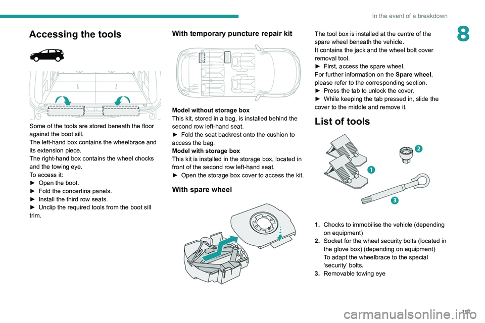
against the boot sill.
The left-hand box contains the wheelbrace and
its extension piece.
The right-hand box contains the wheel chocks
and the towing eye.
To access it:
►
Open the boot.
►
Fold the concertina panels.
►
Install the third row seats.
►
Unclip the required tools from the boot sill
trim.
With temporary puncture repair kit
Model without storage box
This kit, stored in a bag, is installed behind the
second row left-hand seat.
►
Fold the seat backrest onto the cushion to
access the bag.
Model with storage box
This kit is installed in the storage box, located in
front of the second row left-hand seat.
►
Open the storage box cover to access the kit.
With spare wheel
The tool box is installed at the centre of the
spare wheel beneath the vehicle.
It contains the jack and the wheel bolt cover
removal tool.
►
First, access the spare wheel.
For further information on the
Spare wheel,
please refer to the corresponding section.
►
Press the tab to unlock the cover
.
►
While keeping the tab pressed in, slide the
cover to the middle and remove it.
List of tools
1. Chocks to immobilise the vehicle (depending
on equipment)
2. Socket for the wheel security bolts (located in
the glove box) (depending on equipment)
To adapt the wheelbrace to the special
‘security’ bolts.
3. Removable towing eye
Page 194 of 292
192
In the event of a breakdown
The vehicle's electric system allows the connection of the compressor to the 12 V
power supply for long enough to repair a tyre
after a puncture.
Only the 12 V socket located at the front
of the vehicle can be used to power the
compressor.
For more information on the Tool kit,
refer to the corresponding section.
Tyre inflation pressures are indicated on this label.
For more information on Identification
markings, particularly this label, refer to the
corresponding section.
Should the pressure of one or more tyres
be adjusted, it is necessary to reinitialise
the under-inflation detection system.
For more information on Tyre under-inflation
detection, refer to the corresponding section.
Repair procedure
Do not remove any foreign bodies (e.g.
nail, screw) which have penetrated into
the tyre.
For more information on Towing the vehicle
and using the removable towing eye, refer to the
corresponding section.
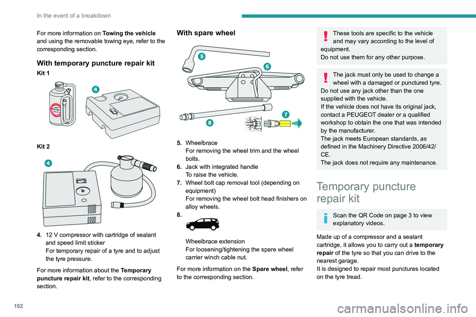
With temporary puncture repair kit
Kit 1
Kit 2
4. 12 V compressor with cartridge of sealant
and speed limit sticker
For temporary repair of a tyre and to adjust
the tyre pressure.
For more information about the Temporary
puncture repair kit, refer to the corresponding
section.
With spare wheel
5. Wheelbrace
For removing the wheel trim and the wheel
bolts.
6. Jack with integrated handle
To raise the vehicle.
7. Wheel bolt cap removal tool (depending on
equipment)
For removing the wheel bolt head finishers on
alloy wheels.
8.
Wheelbrace extension
For loosening/tightening the spare wheel
carrier winch cable nut.
For more information on the Spare wheel, refer
to the corresponding section.
These tools are specific to the vehicle and may vary according to the level of
equipment.
Do not use them for any other purpose.
The jack must only be used to change a wheel with a damaged or punctured tyre.
Do not use any jack other than the one
supplied with the vehicle.
If the vehicle does not have its original jack,
contact a PEUGEOT dealer or a qualified
workshop to obtain the one that was intended
by the manufacturer.
The jack meets European standards, as
defined in the Machinery Directive 2006/42/
CE.
The jack does not require any maintenance.
Temporary puncture repair kit
Scan the QR Code on page 3 to view
explanatory videos.
Made up of a compressor and a sealant
cartridge,
it allows you to carry out a temporary
repair of the tyre so that you can drive to the
nearest garage.
It is designed to repair most punctures located
on the tyre tread.
Page 197 of 292
195
In the event of a breakdown
8With a tyre repaired using this type of kit,
do not exceed a speed of 50 mph
(80
km/h) and do not drive more than
125
miles (200 km).
Contact a PEUGEOT dealer or a qualified
workshop to have the tyre changed.
Checking/adjusting tyre
pressures
The compressor can be used, without injecting
sealant, to check and, if necessary, adjust the
tyre pressures.
►
Remove the valve cap from the tyre and keep
it in a clean place.
►
Uncoil
the pipe stowed under the compressor.
►
Screw the pipe onto the valve and tighten
firmly
.
►
Check that the compressor switch is in
position " O
".
►
Fully uncoil the electric cable stowed under
the compressor
.
►
Connect the compressor's electric plug to the
vehicle's 12
V socket.
►
Switch the ignition on.
►
Start the compressor by placing the switch at
position " I
" and adjust the pressure to the value
shown on the vehicle's tyre pressure label. To
deflate: press the black button located on the
compressor pipe, near the valve connection.
If after 7 minutes the pressure of 2 bar is
not reached, the tyre is damaged;
contact a PEUGEOT dealer or a qualified
workshop for assistance.
►
Once the correct pressure is reached, put the
switch in position " O
".
►
Remove the kit and stow it.
►
Refit the cap on the valve.
Spare wheel
Scan the QR Code on page 3 to view
explanatory videos.
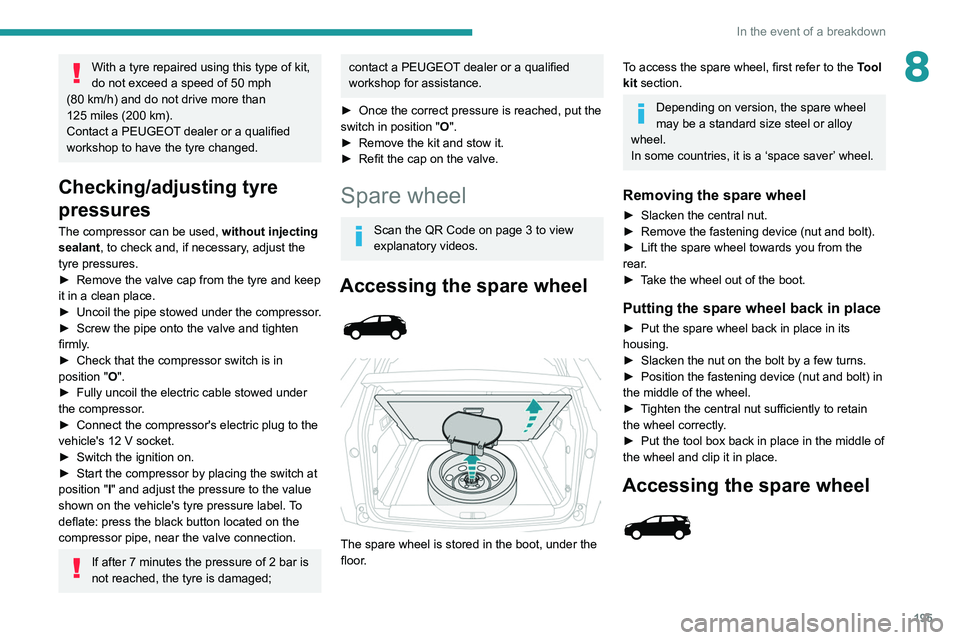
Accessing the spare wheel
The spare wheel is stored in the boot, under the
floor.
To access the spare wheel, first refer to the Tool
kit section.
Depending on version, the spare wheel
may be a standard size steel or alloy
wheel.
In some countries, it is a ‘space saver’ wheel.
Removing the spare wheel
► Slacken the central nut.
► Remove the fastening device (nut and bolt).
►
Lift the spare wheel towards you from the
rear
.
►
T
ake the wheel out of the boot.
Putting the spare wheel back in place
► Put the spare wheel back in place in its
housing.
►
Slacken the nut on the bolt by a few turns.
►
Position the fastening device (nut and bolt) in
the middle of the wheel.
►
T
ighten the central nut sufficiently to retain
the wheel correctly.
►
Put the tool box back in place in the middle of
the wheel and clip it in place.
Accessing the spare wheel
Page 198 of 292
196
In the event of a breakdown
► Reel in the winch by loosening the winch
control nut with wheelbrace 5 and extension
piece 8: the nut should rotate freely once the
cable is completely reeled in.
► Store the rest of the tools in the storage
areas in the boot sill trim.
The punctured wheel cannot be secured beneath the vehicle; it must be stored in
the boot (use a cover to protect the inside of
the boot).
Putting the winch and spare wheel
back in place
► Place the appropriate tools in the box and
close the cover.
► Place the tool box on the ground.
When the spare wheel is fitted in place of
a wheel with a punctured tyre, the winch
and tool box must be placed beneath the
vehicle again before restarting.
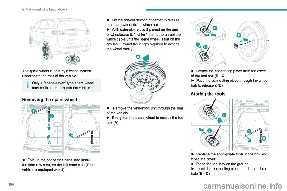
The spare wheel is held by a winch system
underneath the rear of the vehicle.
Only a "space-saver" type spare wheel
may be fixed underneath the vehicle.
Removing the spare wheel
► Fold up the concertina panel and install
the third row seat, on the left-hand side (if the
vehicle is equipped with it). ►
Lift the pre-cut section of carpet to release
the spare wheel
fixing winch nut.
►
With extension piece
8
placed on the end
of wheelbrace 5, "tighten" the nut to unreel the
winch cable until the spare wheel is flat on the
ground. Unwind the length required to access
the wheel easily.
► Remove the wheel/box unit through the rear
of the vehicle.
►
Straighten the spare wheel to access the tool
box (
A).
► Detach the connecting piece from the cover
of the tool box ( B - C).
►
Pass the connecting piece through the wheel
hub to release it ( D
).
Storing the tools
► Replace the appropriate tools in the box and
close the cover .
►
Place the tool box on the ground.
►
Insert the connecting piece into the tool box
hole (
B - C).
Page 199 of 292
197
In the event of a breakdown
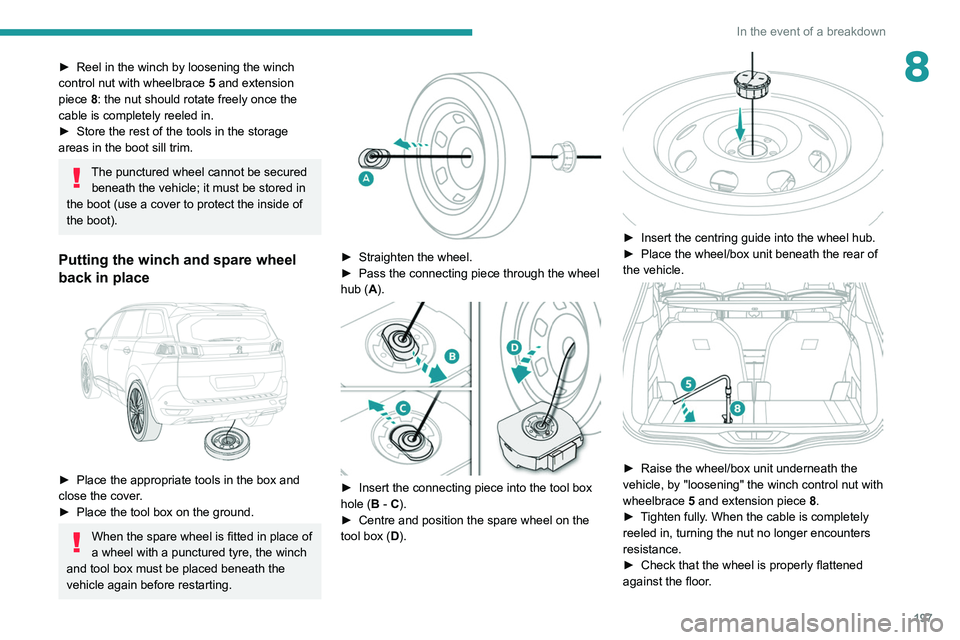
8► Reel in the winch by loosening the winch
control nut with wheelbrace 5
and extension
piece 8: the nut should rotate freely once the
cable is completely reeled in.
►
Store the rest of the tools in the storage
areas in the boot sill trim.
The punctured wheel cannot be secured beneath the vehicle; it must be stored in
the boot (use a cover to protect the inside of
the boot).
Putting the winch and spare wheel
back in place
► Place the appropriate tools in the box and
close the cover .
►
Place the tool box on the ground.
When the spare wheel is fitted in place of
a wheel with a punctured tyre, the winch
and tool box must be placed beneath the
vehicle again before restarting.
► Straighten the wheel.
► Pass the connecting piece through the wheel
hub (
A).
► Insert the connecting piece into the tool box
hole ( B - C).
►
Centre and position the spare wheel on the
tool box (
D).
► Insert the centring guide into the wheel hub.
► Place the wheel/box unit beneath the rear of
the vehicle.
► Raise the wheel/box unit underneath the
vehicle, by "loosening" the winch control nut with
wheelbrace 5
and extension piece 8.
►
T
ighten fully. When the cable is completely
reeled in, turning the nut no longer encounters
resistance.
►
Check that the wheel is properly flattened
against the floor
.