2022 NISSAN TITAN engine
[x] Cancel search: enginePage 347 of 635
Apply the parking brake. When parking on a
hill, apply the parking brake first, then move
the shif t lever into the P (Park) position.
R (Reverse)
CAUTION
To prevent transmission damage, use
the R (Reverse) position only when the
vehicle is completely stopped.
Use the R (Reverse) position to back up.
Make sure the vehicle is completely
stopped before selecting the R (Reverse)
position. The brake pedal must be de-
pressed to move the shif t lever from P
(Park), N (Neutral) or any drive position to
R (Reverse).
N (Neutral)
Neither forward nor reverse gear is en-
gaged. The engine can be started in this
position. You may shif t to N (Neutral) and
restart a stalled engine while the vehicle is
moving.
D (Drive)
Use this position for all normal forward
driving.
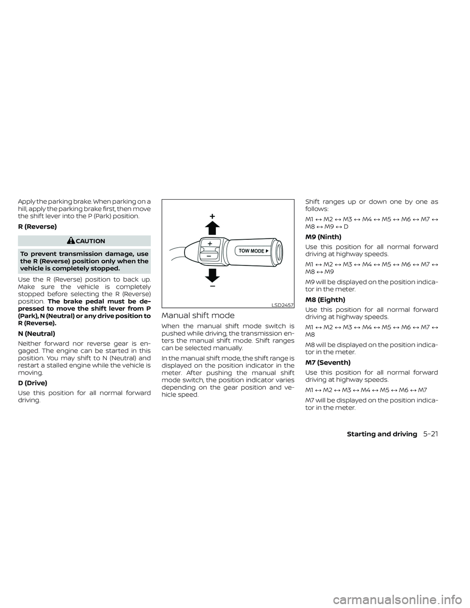
Manual shif t mode
When the manual shif t mode switch is
pushed while driving, the transmission en-
ters the manual shif t mode. Shif t ranges
can be selected manually.
In the manual shif t mode, the shif t range is
displayed on the position indicator in the
meter. Af ter pushing the manual shif t
mode switch, the position indicator varies
depending on the gear position and ve-
hicle speed. Shif t ranges up or down one by one as
follows:
M1
↔M2 ↔M3 ↔M4 ↔M5 ↔M6 ↔M7 ↔
M8 ↔M9 ↔D
M9 (Ninth)
Use this position for all normal forward
driving at highway speeds.
M1 ↔M2 ↔M3 ↔M4 ↔M5 ↔M6 ↔M7 ↔
M8 ↔M9
M9 will be displayed on the position indica-
tor in the meter.
M8 (Eighth)
Use this position for all normal forward
driving at highway speeds.
M1 ↔M2 ↔M3 ↔M4 ↔M5 ↔M6 ↔M7 ↔
M8
M8 will be displayed on the position indica-
tor in the meter.
M7 (Seventh)
Use this position for all normal forward
driving at highway speeds.
M1 ↔M2 ↔M3 ↔M4 ↔M5 ↔M6 ↔M7
M7 will be displayed on the position indica-
tor in the meter.
LSD2457
Starting and driving5-21
Page 348 of 635
M6 (Sixth)
Use this position for all normal forward
driving at highway speeds.
M1↔M2 ↔M3 ↔M4 ↔M5 ↔M6
M6 will be displayed on the position indica-
tor in the meter
M5 (Fif th)
For driving up or down long slopes where
engine braking would be advantageous.
Shif t ranges up or down one by one as
follows:
M1 ↔M2 ↔M3 ↔M4 ↔M5
M5 will be displayed on the position indica-
tor in the meter.
M4 (Fourth)
Use for hill climbing or engine braking on
downhill grades.
Shif t ranges up or down one by one as
follows:
M1 ↔M2 ↔M3 ↔M4
M4 will be displayed on the position indica-
tor in the meter.
M3 (Third)
Use for hill climbing or engine braking on
downhill grades.
Shif t ranges up or down one by one as
follows:
M1 ↔M2 ↔M3
M3 will be displayed on the position indica-
tor in the meter.
M2 (Second)
Use for hill climbing or engine braking on
downhill grades.
Shif t ranges up or down one by one as
follows:
M1 ↔M2
M2 will be displayed on the position indica-
tor in the meter.
M1 (First)
Use this position when climbing steep hills
slowly or driving slowly through deep snow,
sand or mud, or for maximum engine brak-
ing on steep downhill grades.
M1 will be displayed on the position indica-
tor on the meter. • Remember not to drive at high speeds for
extended periods of time in lower than
M4 range. This reduces fuel economy.
When shif ting up
Push the shif t switch to the + (up) side.
(Shif ts to higher range.)
When shif ting down
Push the shif t switch to the − (down) side.
(Shif ts to lower range.)
• The transmission will automatically downshif t the gears. (For example, if you
select the 3rd range, the transmission will
shif t down between the 3rd and 1st
gears.)
• Pushing the shif t switch rapidly will shif t the ranges in succession.
When canceling the manual shif t mode
Press and hold the +(UP) button to return
the transmission to the normal driving
mode.
5-22Starting and driving
Page 352 of 635

TURNING THE TRAFFIC SIGN
RECOGNITION (TSR) SYSTEM ON
AND OFF
Perform the following steps to enable or
disable the TSR system.
1. Press the
button until “Settings” dis-
plays in the vehicle information display.
Use the
button to select “Driver As-
sistance.” Then press the ENTER button.
2. Select “Traffic Sign” and press the ENTER button to turn the system on or off.
SYSTEM TEMPORARILY
UNAVAILABLE
If the vehicle is parked in direct sunlight
under high temperature conditions (over
approximately 104°F [40°C]) and then
started, the TSR system may be deacti-
vated automatically. The “Not Available
High Camera Temp” warning message will
appear in the vehicle information display.
Action to take:
When the interior temperature is reduced,
the TSR system will resume operating
automatically.
SYSTEM MALFUNCTION
If the TSR system malfunctions, it will be
turned off automatically and the system
“Malfunction” warning message will appear
in the vehicle information display.
Action to take:
If the TSR “Malfunction” message appears,
pull off the road at a safe location and stop
the vehicle. Turn the engine off and restart
the engine. If the TSR “Malfunction” mes-
sage continues to appear, have the system
checked. It is recommended that you visit a
NISSAN dealer for this service.
SYSTEM MAINTENANCE
The TSR system uses the same multi-
sensing front camera unit that is used by
the Lane Departure Warning (LDW) system,
located in front of the interior rearview mir-
ror. For additional information, see ”System
maintenance” (P. 5-31).
LSD4011
5-26Starting and driving
Page 357 of 635
![NISSAN TITAN 2022 Owners Manual SYSTEM TEMPORARILY DISABLED
If the vehicle is parked in direct sunlight
under high temperature conditions (over
approximately 104°F [40°C]) and then
started, the LDW system may be deacti-
vated auto NISSAN TITAN 2022 Owners Manual SYSTEM TEMPORARILY DISABLED
If the vehicle is parked in direct sunlight
under high temperature conditions (over
approximately 104°F [40°C]) and then
started, the LDW system may be deacti-
vated auto](/manual-img/5/56788/w960_56788-356.png)
SYSTEM TEMPORARILY DISABLED
If the vehicle is parked in direct sunlight
under high temperature conditions (over
approximately 104°F [40°C]) and then
started, the LDW system may be deacti-
vated automatically and the following
message will appear in the vehicle infor-
mation display: “Not Available High Camera
Temp.”
When the interior temperature is reduced,
the LDW system will resume operating
automatically.
The LDW system is not designed to warn
under the following conditions:
• When you operate the lane change signaland change traveling lanes in the direc-
tion of the signal. (The LDW system will
become operable again approximately 2
seconds af ter the lane change signal is
turned off.)
• When the vehicle speed lowers to less than approximately 37 mph (60 km/h).
Af ter the above conditions have finished
and the necessary operating conditions
are satisfied, the LDW functions will resume.
SYSTEM MALFUNCTION
If the LDW system malfunctions, it will can-
cel automatically and “Malfunction” will ap-
pear in the vehicle information display. If “
Malfunction” appears in the vehicle infor-
mation display, pull off the road to a safe
location and stop the vehicle. Place the
shif t lever in the P (Park) position and the
ignition switch in the OFF position and re-
start the engine/motor. If “Malfunction”
continues to appear in the vehicle informa-
tion display, have the system checked. It is
recommended that you visit a NISSAN
dealer for this service.
SYSTEM MAINTENANCE
The lane camera unitO1for the LDW sys-
tem is located above the inside mirror. To
keep the proper operation of the LDW sys-
tem and prevent a system malfunction, be
sure to observe the following:
• Always keep the windshield clean.
• Do not attach a sticker (including trans- parent material) or install an accessory
near the camera unit.
LSD3707
Starting and driving5-31
Page 361 of 635
When the BSW system is enabled in the
vehicle information display, the system can
be turned off temporarily by pushing the
warning systems switch. For additional in-
formation, see “Warning systems switch”
(P. 2-57).
Perform the following steps to enable or
disable the BSW system:
1. Press the
button until “Settings” dis-
plays in the vehicle information display.
Use the
button to select “Driver As-
sistance” and press ENTER.
2. Select “Blind Spot” and press ENTER.
3. Select “Warning (BSW)” and press ENTER.
4. Push the Warning systems switch to turn the system on or off.
NOTE:
• When enabling/disabling the system,the system will retain current settings
even if the engine is restarted.
• When the BSW system is turned on, the BSW/RCTA indicator (white) in the ve-
hicle information display illuminates.
BSW SYSTEM LIMITATIONS
WARNING
Listed below are the system limitations
for the BSW system. Failure to operate
the vehicle in accordance with these
system limitations could result in seri-
ous injury or death.
• The BSW system cannot detect all ve-
hicles under all conditions.
• The radar sensors may not be able to
detect and activate BSW when cer-
tain objects are present such as:
– Pedestrian, bicycles, animals.
– Vehicles such as motorcycles, low
height vehicles, or high ground
clearance vehicles.
– Oncoming vehicles.
– Vehicles remaining in the detec-
tion zone when you accelerate
from a stop.
– A vehicle merging into an adjacent
lane at a speed approximately the
same as your vehicle.
– A vehicle approaching rapidly
from behind.
– A vehicle which your vehicle over-
takes rapidly. –
A vehicle that passes through the
detection zone quickly.
– When overtaking several vehicles
in a row, the vehicles af ter the first
vehicle may not be detected if
they are traveling close together.
• The radar sensor’s detection zone is
designed based on a standard lane
width. When driving in a wider lane,
the radar sensors may not detect ve-
hicles in an adjacent lane. When driv-
ing in a narrow lane, the radar sen-
sors may detect vehicles driving two
lanes away.
• The radar sensors are designed to ig-
nore most stationary objects; how-
ever, objects such as guardrails,
walls, foliage and parked vehicles
may occasionally be detected. This is
a normal operation condition.
• The following conditions may reduce
the ability of the radar to detect other
vehicles:
– Severe weather
– Road spray
– Ice/frost/snow/dirt build-up on
the vehicle
Starting and driving5-35
Page 367 of 635
Action to take:
Stop the vehicle in a safe location, place the
vehicle in the P (Park) position, turn the en-
gine off and restart the engine. If the mes-
sage continues to appear, have the system
checked. It is recommended that you visit a
NISSAN dealer for this service.
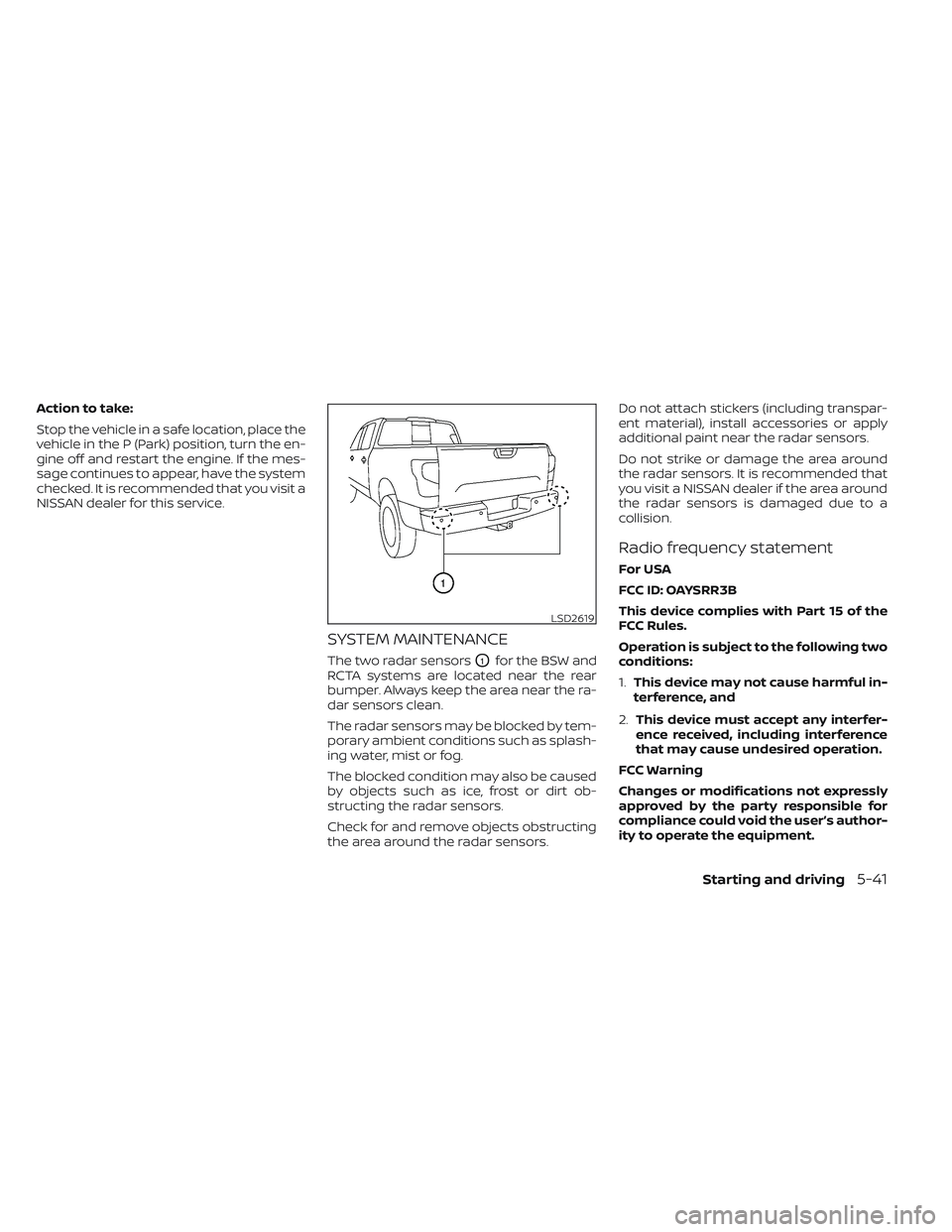
SYSTEM MAINTENANCE
The two radar sensorsO1for the BSW and
RCTA systems are located near the rear
bumper. Always keep the area near the ra-
dar sensors clean.
The radar sensors may be blocked by tem-
porary ambient conditions such as splash-
ing water, mist or fog.
The blocked condition may also be caused
by objects such as ice, frost or dirt ob-
structing the radar sensors.
Check for and remove objects obstructing
the area around the radar sensors. Do not attach stickers (including transpar-
ent material), install accessories or apply
additional paint near the radar sensors.
Do not strike or damage the area around
the radar sensors. It is recommended that
you visit a NISSAN dealer if the area around
the radar sensors is damaged due to a
collision.
Radio frequency statement
For USA
FCC ID: OAYSRR3B
This device complies with Part 15 of the
FCC Rules.
Operation is subject to the following two
conditions:
1.
This device may not cause harmful in-
terference, and
2. This device must accept any interfer-
ence received, including interference
that may cause undesired operation.
FCC Warning
Changes or modifications not expressly
approved by the party responsible for
compliance could void the user’s author-
ity to operate the equipment.
LSD2619
Starting and driving5-41
Page 370 of 635
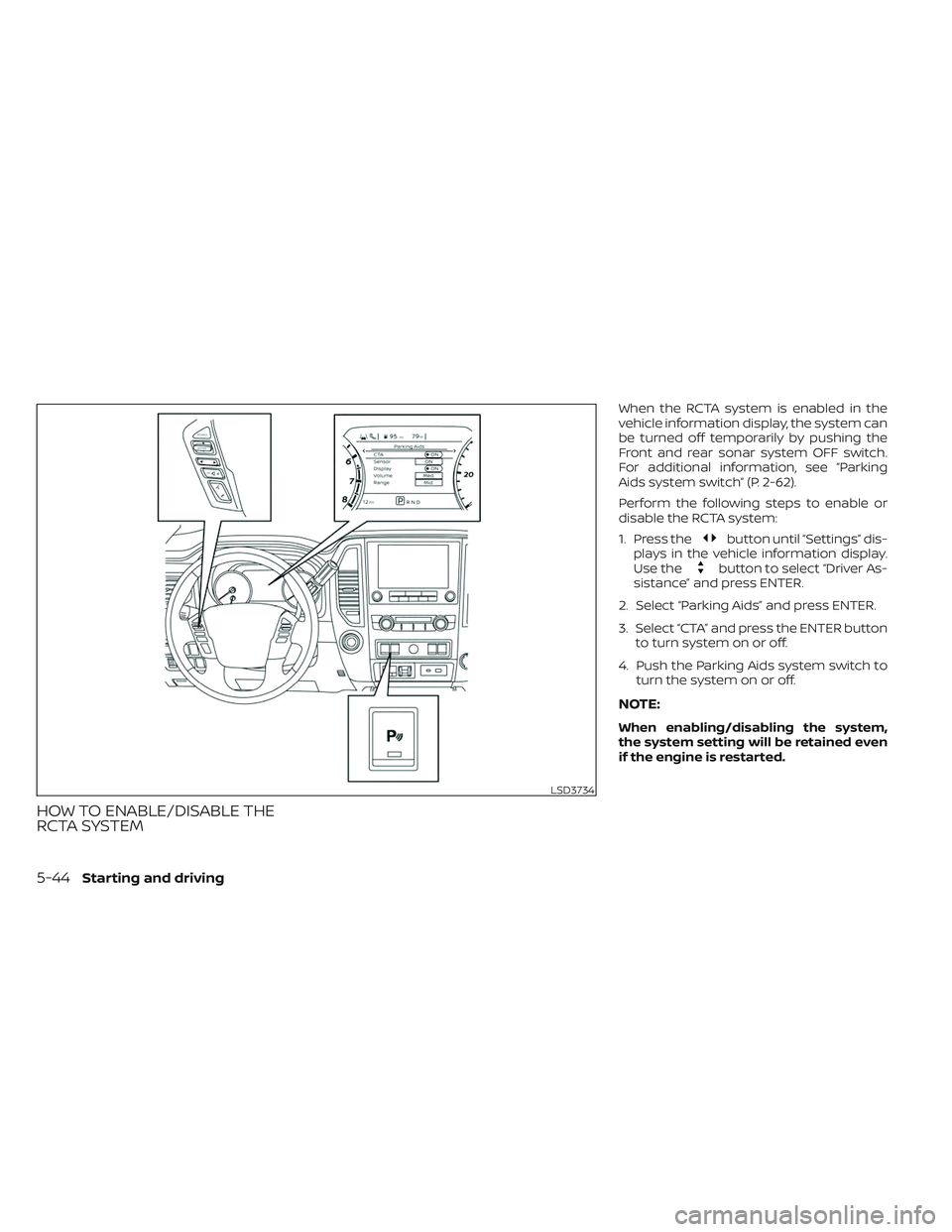
HOW TO ENABLE/DISABLE THE
RCTA SYSTEM
When the RCTA system is enabled in the
vehicle information display, the system can
be turned off temporarily by pushing the
Front and rear sonar system OFF switch.
For additional information, see “Parking
Aids system switch” (P. 2-62).
Perform the following steps to enable or
disable the RCTA system:
1. Press the
button until “Settings” dis-
plays in the vehicle information display.
Use the
button to select “Driver As-
sistance” and press ENTER.
2. Select “Parking Aids” and press ENTER.
3. Select “CTA” and press the ENTER button to turn system on or off.
4. Push the Parking Aids system switch to turn the system on or off.
NOTE:
When enabling/disabling the system,
the system setting will be retained even
if the engine is restarted.
LSD3734
5-44Starting and driving
Page 374 of 635

Malfunction
When the RCTA system malfunctions, it will
turn off automatically. The system mal-
function warning message with the BSW/
RCTA indicator (orange) will appear in the
vehicle information display.
NOTE:
If the BSW system stops working, the
RCTA system will also stop working.
Action to take
Stop the vehicle in a safe location, place the
vehicle in the P (Park) position, turn the en-
gine off and restart the engine. If the mes-
sage continues to appear, have the system
checked. It is recommended that you visit a
NISSAN dealer for this service.
SYSTEM MAINTENANCE
The two radar sensorsO1for the BSW and
RCTA systems are located near the rear
bumper. Always keep the area near the ra-
dar sensors clean.
The radar sensors may be blocked by tem-
porary ambient conditions such as splash-
ing water, mist or fog.
The blocked condition may also be caused
by objects such as ice, frost or dirt ob-
structing the radar sensors.
Check for and remove objects obstructing
the area around the radar sensors. Do not attach stickers (including transpar-
ent material), install accessories or apply
additional paint near the radar sensors.
Do not strike or damage the area around
the radar sensors. It is recommended that
you visit a NISSAN dealer if the area around
the radar sensors is damaged due to a
collision.
Radio frequency statement
For USA
FCC ID: OAYSRR3B
This device complies with Part 15 of the
FCC Rules.
Operation is subject to the following two
conditions:
1.
This device may not cause harmful
interference, and
2. This device must accept any interfer-
ence received, including interference
that may cause undesired operation.
FCC Warning
Changes or modifications not expressly
approved by the party responsible for
compliance could void the user’s author-
ity to operate the equipment.
LSD2619
5-48Starting and driving