Page 14 of 635
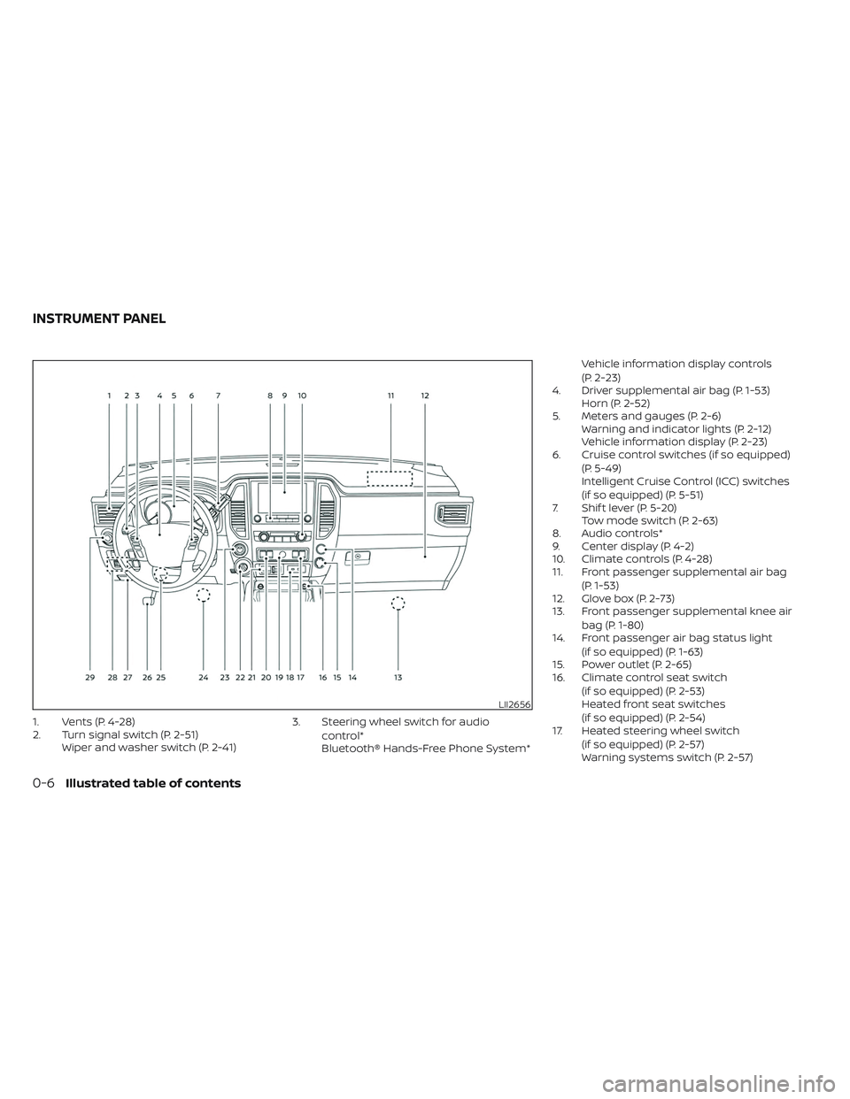
1. Vents (P. 4-28)
2. Turn signal switch (P. 2-51)Wiper and washer switch (P. 2-41) 3. Steering wheel switch for audio
control*
Bluetooth® Hands-Free Phone System* Vehicle information display controls
(P. 2-23)
4. Driver supplemental air bag (P. 1-53) Horn (P. 2-52)
5. Meters and gauges (P. 2-6) Warning and indicator lights (P. 2-12)
Vehicle information display (P. 2-23)
6. Cruise control switches (if so equipped)
(P. 5-49)
Intelligent Cruise Control (ICC) switches
(if so equipped) (P. 5-51)
7. Shif t lever (P. 5-20) Tow mode switch (P. 2-63)
8. Audio controls*
9. Center display (P. 4-2)
10. Climate controls (P. 4-28)
11. Front passenger supplemental air bag
(P. 1-53)
12. Glove box (P. 2-73)
13. Front passenger supplemental knee air
bag (P. 1-80)
14. Front passenger air bag status light
(if so equipped) (P. 1-63)
15. Power outlet (P. 2-65)
16. Climate control seat switch
(if so equipped) (P. 2-53)
Heated front seat switches
(if so equipped) (P. 2-54)
17. Heated steering wheel switch
(if so equipped) (P. 2-57)
Warning systems switch (P. 2-57)
LII2656
INSTRUMENT PANEL
0-6Illustrated table of contents
Page 15 of 635
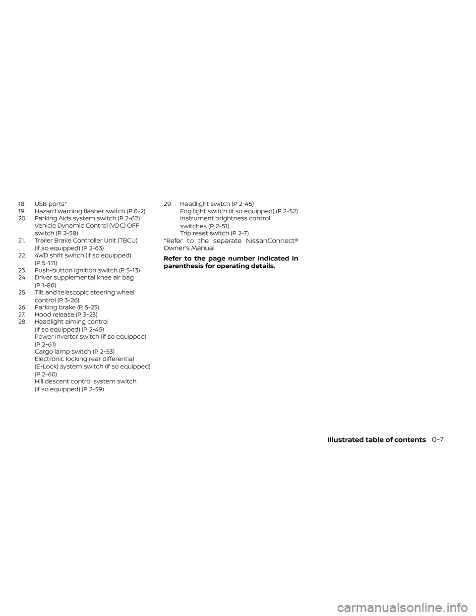
18. USB ports*
19. Hazard warning flasher switch (P. 6-2)
20. Parking Aids system switch (P. 2-62)Vehicle Dynamic Control (VDC) OFF
switch (P. 2-58)
21. Trailer Brake Controller Unit (TBCU)
(if so equipped) (P. 2-63)
22. 4WD shif t switch (if so equipped)
(P. 5-111)
23. Push-button ignition switch (P. 5-13)
24. Driver supplemental knee air bag
(P. 1-80)
25. Tilt and telescopic steering wheel
control (P. 3-26)
26. Parking brake (P. 5-23)
27. Hood release (P. 3-23)
28. Headlight aiming control
(if so equipped) (P. 2-45)
Power inverter switch (if so equipped)
(P. 2-61)
Cargo lamp switch (P. 2-53)
Electronic locking rear differential
(E-Lock) system switch (if so equipped)
(P. 2-60)
Hill descent control system switch
(if so equipped) (P. 2-59) 29. Headlight switch (P. 2-45)
Fog light switch (if so equipped) (P. 2-52)
Instrument brightness control
switches (P. 2-51)
Trip reset switch (P. 2-7)
*Refer to the separate NissanConnect®
Owner’s Manual
Refer to the page number indicated in
parenthesis for operating details.
Illustrated table of contents0-7
Page 16 of 635
5.6L 8 cylinder (VK56VD engine)
(non-XD model)
1. Windshield-washer fluid reservoir(P. 8-15)
2. Fuse box (P. 8-24)
3. Engine oil dipstick (P. 8-7)
4. Power steering fluid reservoir (P. 8-13)
5. Engine oil filler cap (P. 8-7)
6. Brake fluid reservoir (P. 8-14)
7. Air cleaner (P. 8-21)
8. Fuse/Fusible link box (P. 8-24)
9. Drive belt location (P. 8-20)
10. Radiator cap (P. 8-5)
11. Battery (P. 8-16)
12. Engine coolant reservoir (P. 8-5)
NOTE:
Your vehicle may not be equipped with
an engine cover.
Refer to the page number indicated in
parentheses for operating details.
LDI3292
ENGINE COMPARTMENT CHECK
LOCATIONS
0-8Illustrated table of contents
Page 17 of 635
5.6L 8 cylinder (VK56VD engine)
(XD model)
1. Windshield-washer fluid reservoir(P. 8-15)
2. Fuse box (P. 8-24)
3. Engine oil dipstick (P. 8-7)
4. Power steering fluid reservoir (P. 8-13)
5. Engine oil filler cap (P. 8-7)
6. Brake fluid reservoir (P. 8-14)
7. Air cleaner (P. 8-21)
8. Fuse/Fusible link box (P. 8-24)
9. Engine coolant reservoir (P. 8-5)
10. Drive belt location (P. 8-20)
11. Battery (P. 8-16)
12. Radiator cap (P. 8-5)
NOTE:
Your vehicle may not be equipped with
an engine cover.
Refer to the page number indicated in
parentheses for operating details.
LDI3293
Illustrated table of contents0-9
Page 110 of 635
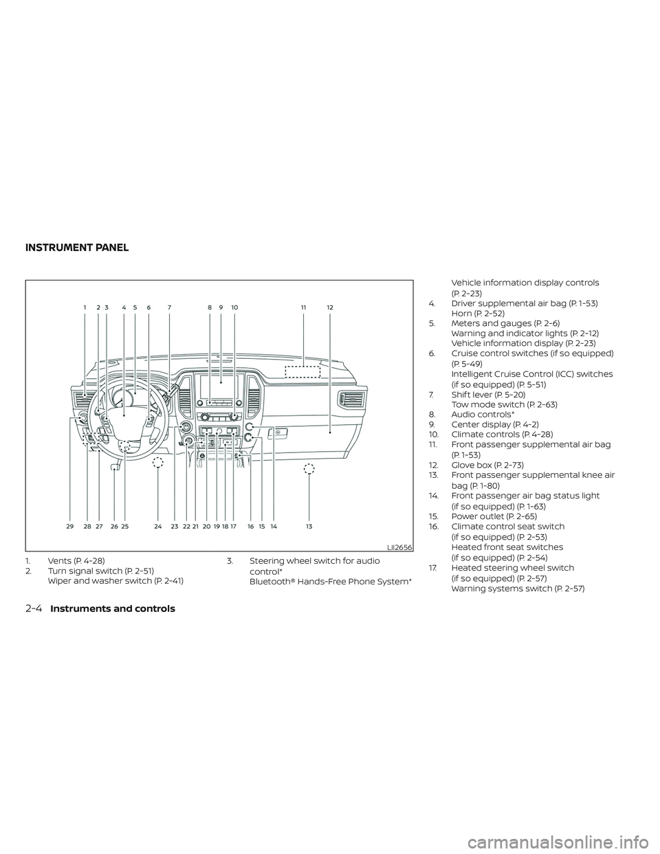
1. Vents (P. 4-28)
2. Turn signal switch (P. 2-51)Wiper and washer switch (P. 2-41) 3. Steering wheel switch for audio
control*
Bluetooth® Hands-Free Phone System* Vehicle information display controls
(P. 2-23)
4. Driver supplemental air bag (P. 1-53) Horn (P. 2-52)
5. Meters and gauges (P. 2-6) Warning and indicator lights (P. 2-12)
Vehicle information display (P. 2-23)
6. Cruise control switches (if so equipped)
(P. 5-49)
Intelligent Cruise Control (ICC) switches
(if so equipped) (P. 5-51)
7. Shif t lever (P. 5-20) Tow mode switch (P. 2-63)
8. Audio controls*
9. Center display (P. 4-2)
10. Climate controls (P. 4-28)
11. Front passenger supplemental air bag
(P. 1-53)
12. Glove box (P. 2-73)
13. Front passenger supplemental knee air
bag (P. 1-80)
14. Front passenger air bag status light
(if so equipped) (P. 1-63)
15. Power outlet (P. 2-65)
16. Climate control seat switch
(if so equipped) (P. 2-53)
Heated front seat switches
(if so equipped) (P. 2-54)
17. Heated steering wheel switch
(if so equipped) (P. 2-57)
Warning systems switch (P. 2-57)
LII2656
INSTRUMENT PANEL
2-4Instruments and controls
Page 111 of 635
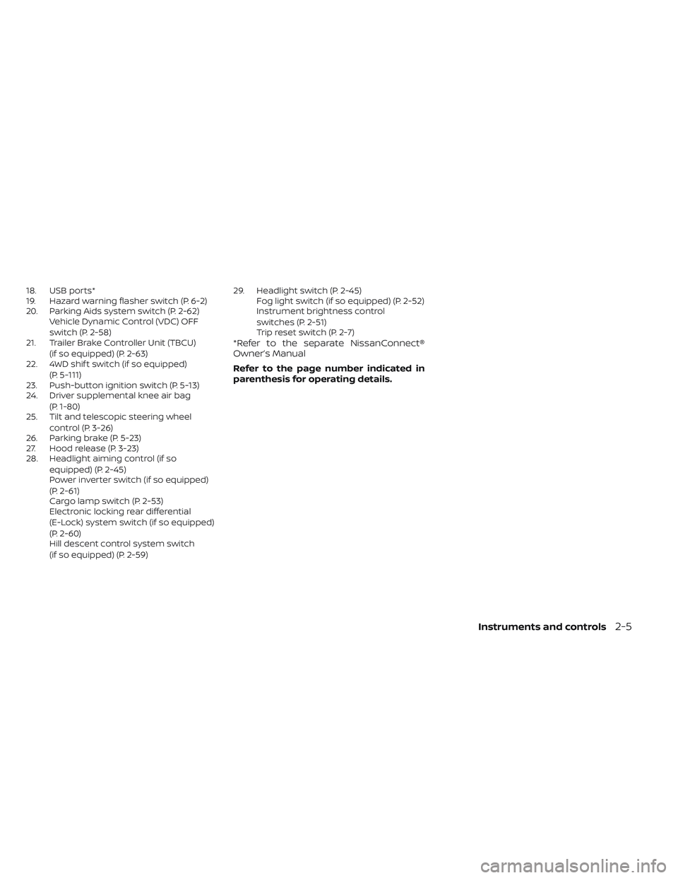
18. USB ports*
19. Hazard warning flasher switch (P. 6-2)
20. Parking Aids system switch (P. 2-62)Vehicle Dynamic Control (VDC) OFF
switch (P. 2-58)
21. Trailer Brake Controller Unit (TBCU)
(if so equipped) (P. 2-63)
22. 4WD shif t switch (if so equipped)
(P. 5-111)
23. Push-button ignition switch (P. 5-13)
24. Driver supplemental knee air bag
(P. 1-80)
25. Tilt and telescopic steering wheel
control (P. 3-26)
26. Parking brake (P. 5-23)
27. Hood release (P. 3-23)
28. Headlight aiming control (if so
equipped) (P. 2-45)
Power inverter switch (if so equipped)
(P. 2-61)
Cargo lamp switch (P. 2-53)
Electronic locking rear differential
(E-Lock) system switch (if so equipped)
(P. 2-60)
Hill descent control system switch
(if so equipped) (P. 2-59) 29. Headlight switch (P. 2-45)
Fog light switch (if so equipped) (P. 2-52)
Instrument brightness control
switches (P. 2-51)
Trip reset switch (P. 2-7)
*Refer to the separate NissanConnect®
Owner’s Manual
Refer to the page number indicated in
parenthesis for operating details.
Instruments and controls2-5
Page 164 of 635

The BSW system will turn on the side indi-
cator lights, located by the outside mirrors,
if the radar sensors detect a vehicle in the
detection zone. If the turn signal is acti-
vated in the direction of the detected ve-
hicle, a chime sounds twice and the side
indicator light will flash.
The LDW system will sound a warning; the
steering wheel will vibrate; and the LDW
indicator (orange) will blink to alert the
driver of the vehicle is traveling close to
either the lef t or the right of a traveling lane
with detectable lane markers.
For additional information, see “Blind Spot
Warning (BSW)” (P. 5-32) and “Lane Depar-
ture Warning (LDW)” (P. 5-27).The vehicle should be driven with the VDC
system on for most driving conditions.
If the vehicle is stuck in mud or snow, the
VDC system reduces the engine output to
reduce wheel spin. The engine speed will
be reduced even if the accelerator is de-
pressed to the floor. If maximum engine
power is needed to free a stuck vehicle,
turn the VDC system off.
To turn off the VDC system, push the VDC
OFF switch. The
indicator light will
come on. Push the VDC OFF switch again or restart
the engine to turn on the system. For addi-
tional information, see “Vehicle Dynamic
Control (VDC) system” (P. 5-120).
LIC3344
VEHICLE DYNAMIC CONTROL (VDC)
OFF SWITCH
2-58Instruments and controls
Page 167 of 635
•Use the E-lock system only in an
emergency when it is not possible to
free a stuck vehicle even using 4LO.
Never use the E-Lock system on a
slippery road surface such as snow
or ice surface. Using the E-Lock sys-
tem when driving in these road con-
ditions may cause unexpected
movement of the vehicle during en-
gine braking, accelerating or turning,
which may result in an accident and
serious personal injury.
• Observe the above warnings. Other-
wise, loss of normal steering control
may result. This may result in an ac-
cident and serious personal injury.
CAUTION
• Af ter using the E-Lock system, or
during normal driving, turn the
switch OFF to prevent possible dam-
age to drivetrain components from
extended use.
• When the E-Lock system is in opera-
tion, turning the vehicle becomes dif-
ficult. This can be dangerous, espe-
cially at high speeds. Doing so could
damage drivetrain components. •
Do not operate the E-Lock system
when the vehicle is turning or when
one side wheel is rotating. Otherwise,
the drivetrain components could be
damaged.
• The E-Lock system operates only
when the engine is running.
• In 4H mode, the E-Lock system does
not operate when the E-Lock system
switch is turned to the ON position.
(The E-Lock system indicator light
will flash.)
• Avoid quick starts while the E-Lock
system is in operation. Otherwise the
drivetrain components could be
damaged.
• Observe the above cautions. Other-
wise, loss of normal steering may
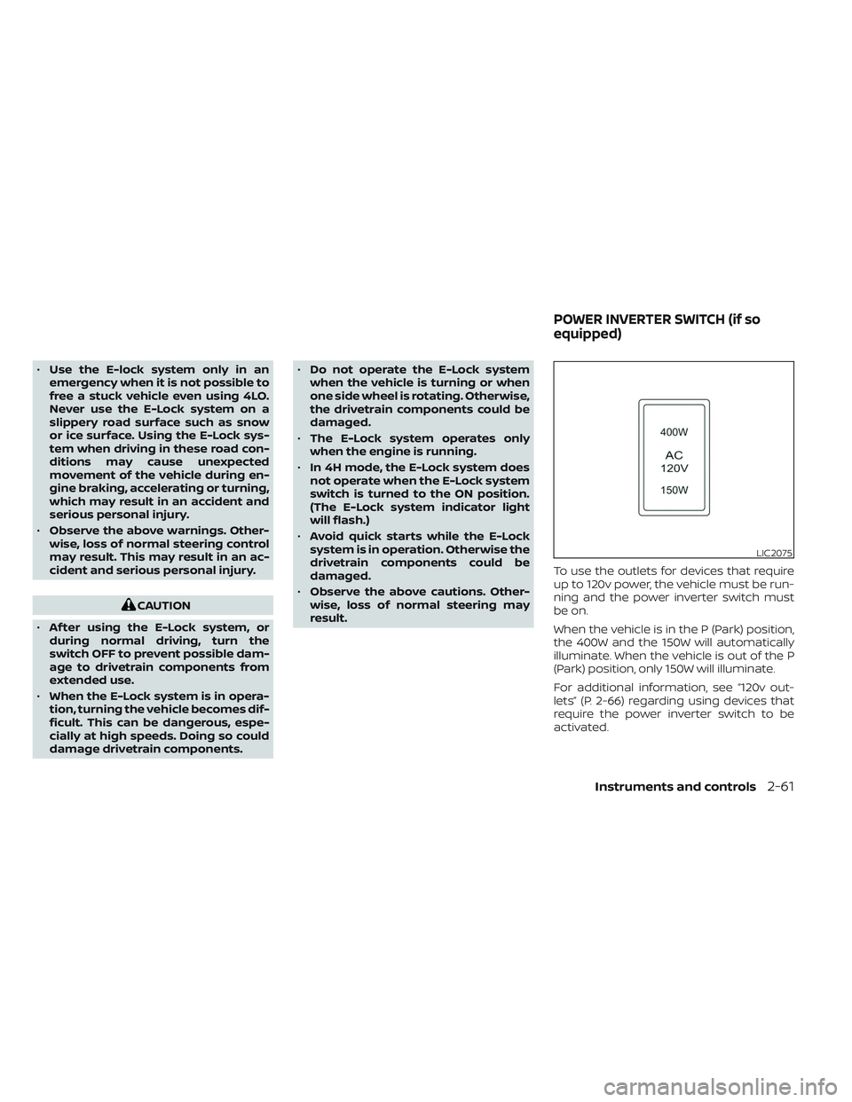
result. To use the outlets for devices that require
up to 120v power, the vehicle must be run-
ning and the power inverter switch must
be on.
When the vehicle is in the P (Park) position,
the 400W and the 150W will automatically
illuminate. When the vehicle is out of the P
(Park) position, only 150W will illuminate.
For additional information, see “120v out-
lets” (P. 2-66) regarding using devices that
require the power inverter switch to be
activated.
LIC2075
POWER INVERTER SWITCH (if so
equipped)
Instruments and controls2-61