2022 NISSAN SENTRA engine
[x] Cancel search: enginePage 244 of 528
mode when Remote Engine Start is acti-
vated depending on outside and cabin
temperatures. During this period, the cli-
mate control display and buttons will be
inoperable until the ignition switch is
turned on. In Remote Engine Start defrost-
ing mode, the rear window defroster and
heated steering wheel (if so equipped) may
be activated automatically.
MANUAL OPERATION
Fan speed control buttons
Press thefan speed control buttons
to manually control the fan speed.
Press the AUTO button to return to auto-
matic control of the fan speed.
Temperature control dial
The temperature control dial allows you to
adjust the temperature of the outlet air. To
lower the temperature, turn the dial to the
lef t. To increase the temperature, turn the
dial to the right. Temperature can be ad-
justed on the driver’s and passenger’s side.
Air recirculation
Press theair recirculation button to
recirculate interior air inside the vehicle.
The
indicator light on the button will
come on.
The air recirculation cannot be activated
when the air conditioner is in the
front
defrosting mode.
When the outside temperature exceeds
70°F (21°C), the air conditioning system may
default to air recirculation mode automati-
cally to reduce overall power consumption.
To exit air recirculation mode, deselect the
air recirculation button (indicator light will
turn off ) to enter fresh air mode.
Automatic intake air control
In the AUTO mode, the intake air will be
controlled automatically. To manually con-
trol the intake air, press the
air recir-
culation button. To return to the automatic
control mode, press and hold the
air
recirculation button for about 2 seconds.
The indicator light will flash twice, and then
the intake air will be controlled automati-
cally.
A/C (air conditioner) button
Start the engine, press thefan speed
control buttons to the desired position and
press the
button to turn on the air
conditioner. To turn off the air conditioner,
press the
button again.
The air conditioner cooling function op-
erates only when the engine is running.
Air flow control
Pressing thebutton manually con-
trols air flow and selects the air outlet:
— Air flows from center and side
vents.
— Air flows from center and sidevents and foot outlets.
— Air flows mainly from foot outlets.— Air flows from defroster and footoutlets.
4-42Monitor, climate, audio, phone and voice recognition systems
Page 246 of 528
• When the climate system is in automaticoperation and the engine coolant tem-
perature and outside air temperature are
low, the air flow outlet may default to de-
froster mode for a maximum of 2 min-
utes 30 seconds. This is not a malfunc-
tion. Af ter the engine coolant
temperature warms up, the air flow outlet
will return to foot mode and operation will
continue normally.
• When the outside and interior cabin tem- peratures are moderate to high, the in-
take setting may default to turn off air
recirculation to allow fresh air into the
passenger compartment. You may no-
tice air flow from the foot mode, bi-level
mode, or side demist vent outlets for a
maximum of 15 seconds. This may occur
when the previous climate setting was
turned off. This is not a malfunction. Af ter
the initial warm air is expelled, the intake
will return to automatic control, the air
flow outlet will return to previous settings,
and operation will continue normally. To
exit, press any climate control button.
• Keep the moonroof (if so equipped) closed while the air conditioner is in op-
eration. • If you feel that the air flow mode you have
selected and the outlets the air is coming
out do not match, select the
mode.
• When you change the air flow mode, you may feel air flow from the foot outlets for
just a moment. This is not a malfunction. The air conditioner system in your NISSAN
vehicle is charged with a refrigerant de-
signed with the environment in mind.
This refrigerant does not harm the
earth's ozone layer.
Special charging equipment and lubricant
is required when servicing your NISSAN air
conditioner. Using improper refrigerants or
lubricants will cause severe damage to
your air conditioner system. For additional
information, refer to “Air conditioner sys-
tem refrigerant and oil recommendations”
in the “Technical and consumer informa-
tion” section of this manual.
It is recommended that you visit a NISSAN
dealer to service your “environmentally
friendly ” air conditioning system.
Page 247 of 528
RADIO
Place the ignition switch in the ACC or ON
position and press the PUSHbutton to
turn the radio on. If you listen to the radio
with the engine not running, the ignition
switch should be placed in the ACC position.
Radio reception is affected by station sig-
nal strength, distance from radio transmit-
ter, buildings, bridges, mountains and other
external influences. Intermittent changes
in reception quality normally are caused by
these external influences.
Using a cellular phone in or near the ve-
hicle may influence radio reception quality.
Radio reception
Your NISSAN radio system is equipped with
state-of-the-art electronic circuits to en-
hance radio reception. These circuits are
designed to extend reception range, and to
enhance the quality of that reception.
However, there are some general charac-
teristics of both FM and AM radio signals
that can affect radio reception quality in a
moving vehicle, even when the finest
equipment is used. These characteristics
are completely normal in a given reception
area and do not indicate any malfunction
in your NISSAN radio system. Reception conditions will constantly
change because of vehicle movement.
Buildings, terrain, signal distance and inter-
ference from other vehicles can work
against ideal reception. Described below
are some of the factors that can affect your
radio reception.
Some cellular phones or other devices may
cause interference or a buzzing noise to
come from the audio system speakers.
Storing the device in a different location
may reduce or eliminate the noise.
FM RADIO RECEPTION
Range: FM range is normally limited to 25 –
30 mi (40 – 48 km), with monaural (single
channel) FM having slightly more range
than stereo FM. External influences may
sometimes interfere with FM station re-
ception even if the FM station is within 25
mi (40 km). The strength of the FM signal is
directly related to the distance between
the transmitter and receiver. FM signals fol-
low a line-of-sight path, exhibiting many of
the same characteristics as light. For ex-
ample, they will reflect off objects.
Fade and drif t: As your vehicle moves away
from a station transmitter, the signals will
tend to fade and/or drif t.
Static and flutter: During signal interfer-
ence from buildings, large hills or due to
antenna position (usually in conjunction
with increased distance from the station
transmitter), static or flutter can be heard.
This can be reduced by adjusting the treble
control to reduce treble response.
Multipath reception: Because of the reflec-
tive characteristics of FM signals, direct and
reflected signals reach the receiver at the
same time. The signals may cancel each
other, resulting in momentary flutter or loss
of sound.AM RADIO RECEPTION
AM signals, because of their low frequency,
can bend around objects and skip along
the ground. In addition, the signals can be
bounced off the ionosphere and bent back
to earth. Because of these characteristics,
AM signals are also subject to interference
as they travel from transmitter to receiver.
Fading: Occurs while the vehicle is passing
through freeway underpasses or in areas
with many tall buildings. It can also occur
for several seconds during ionospheric tur-
bulence even in areas where no obstacles
exist.
AUDIO SYSTEM
Monitor, climate, audio, phone and voice recognition systems4-45
Page 269 of 528
When installing a CB, ham radio or car
phone in your vehicle, be sure to observe
the following precautions; otherwise, the
new equipment may adversely affect the
engine control system and other electronic
parts.CAUTION
• Keep the antenna as far away as pos-
sible from the electronic control
modules.
• Keep the antenna wire more than 8 in
(20 cm) away from the electronic
control system harnesses. Do not
route the antenna wire next to any
harness.
• Adjust the antenna standing-wave
ratio as recommended by the
manufacturer.
• Connect the ground wire from the CB
radio chassis to the body.
• For additional information, it is rec-
ommended that you visit a NISSAN
dealer for this service.WARNING
• Use a phone af ter stopping your ve-
hicle in a safe location. If you have to
use a phone while driving, exercise
extreme caution at all times so full
attention may be given to vehicle
operation.
• If you are unable to devote full atten-
tion to vehicle operation while talk-
ing on the phone, pull off the road to
a safe location and stop your vehicle.
CAUTION
To avoid discharging the vehicle bat-
tery, use a phone af ter starting the en-
gine.
CAR PHONE OR CB RADIO BLUETOOTH® HANDS-FREE PHONE
SYSTEM
Monitor, climate, audio, phone and voice recognition systems4-67
Page 289 of 528
Increasing fuel economy.......................5-111
Parking/parking on hills .......................5-112
Power steering ................................ 5-113
Brake system ................................. 5-114
Brake precautions .......................... 5-114
Anti-lock Braking System (ABS) .............5-114
Brake Assist ................................ 5-116
Vehicle Dynamic Control (VDC) system ........5-116
Rise-up and build-up ....................... 5-118
Brake force distribution ....................5-118
Chassis Control ............................... 5-119
Intelligent Trace Control (I-TC) ..............5-119
Active Ride Control (ARC) ...................5-119
Hill start assist system ........................ 5-119
Rear Sonar System (RSS) ......................5-120System operation
.......................... 5-121
How to enable/disable the sonar
system ..................................... 5-122
Sonar limitations ........................... 5-124
System temporarily unavailable ............5-124
System maintenance ......................5-125
Cold weather driving .......................... 5-125
Freeing a frozen door lock ..................5-125
Antifreeze .................................. 5-125
Battery..................................... 5-125
Draining of coolant water ..................5-126
Tire equipment ............................. 5-126
Special winter equipment ..................5-126
Driving on snow or ice ......................5-126
Engine block heater (if so equipped) ........5-127
Page 291 of 528
•Do not stop or park the vehicle over
flammable materials such as dry
grass, waste paper or rags. They may
ignite and cause a fire.
CAUTION
• Do not use leaded gasoline. Deposits
from leaded gasoline will seriously
reduce the three-way catalyst's abil-
ity to help reduce exhaust pollutants.
• Keep your engine tuned up. Malfunc-
tions in the ignition, fuel injection, or
electrical systems can cause overrich
fuel flow into the three-way catalyst,
causing it to overheat. Do not keep
driving if the engine misfires, or if no-
ticeable loss of performance or other
unusual operating conditions are de-
tected. Have the vehicle inspected
promptly. It is recommended that
you visit a NISSAN dealer for this
service.
• Avoid driving with an extremely low
fuel level. Running out of fuel could
cause the engine to misfire, damag-
ing the three-way catalyst.
• Do not race the engine while warm-
ing it up. •
Do not push or tow your vehicle to
start the engine.
TIRE PRESSURE MONITORING
SYSTEM (TPMS)
Each tire, including the spare (if provided),
should be checked monthly when cold and
inflated to the inflation pressure recom-
mended by the vehicle manufacturer on
the vehicle placard or tire inflation pressure
label. (If your vehicle has tires of a different
size than the size indicated on the vehicle
placard or tire inflation pressure label, you
should determine the proper tire inflation
pressure for those tires.)
As an added safety feature, your vehicle
has been equipped with a Tire Pressure
Monitoring System (TPMS) that illuminates
a low tire pressure telltale when one or
more of your tires is significantly under-
inflated. Accordingly, when the low tire
pressure telltale illuminates, you should
stop and check your tires as soon as pos-
sible, and inflate them to the proper pres-
sure. Driving on a significantly under-
inflated tire causes the tire to overheat and
can lead to tire failure. Under-inflation also
reduces fuel efficiency and tire tread life,
and may affect the vehicle’s handling and
stopping ability. Please note that the TPMS is not a substi-
tute for proper tire maintenance, and it is
the driver’s responsibility to maintain cor-
rect tire pressure, even if under-inflation
has not reached the level to trigger illumi-
nation of the TPMS low tire pressure telltale.
Your vehicle has also been equipped with a
TPMS malfunction indicator to indicate
when the system is not operating properly.
The TPMS malfunction indicator is com-
bined with the low tire pressure telltale.
When the system detects a malfunction,
the telltale will flash for approximately one
minute and then remain continuously illu-
minated. This sequence will continue upon
subsequent vehicle start-ups as long as
the malfunction exists. When the malfunc-
tion indicator is illuminated, the system
may not be able to detect or signal low tire
pressure as intended. TPMS malfunctions
may occur for a variety of reasons, includ-
ing the installation of replacement or alter-
nate tires or wheels on the vehicle that
prevent the TPMS from functioning prop-
erly. Always check the TPMS malfunction
telltale af ter replacing one or more tires or
wheels on your vehicle to ensure that the
replacement or alternate tires and wheels
allow the TPMS to continue to function
properly.
Starting and driving5-5
Page 294 of 528
(2) this device must accept any interfer-
ence received, including interference
that may cause undesired operation.
NOTE:
Changes or modifications not ex-
pressly approved by the party re-
sponsible for compliance could void
the user's authority to operate the
equipment.
For Canada:
This device complies with Industry
Canada licence-exempt RSS standard(s).
Operation is subject to the following two
conditions: (1) this device may not cause
interference, and (2) this device must ac-
cept any interference, including interfer-
ence that may cause undesired opera-
tion of the device.
TPMS with Easy-Fill Tire Alert
When adding air to an under-inflated tire,
the TPMS with Easy-Fill Tire Alert provides
visual and audible signals outside the ve-
hicle to help you inflate the tires to the rec-
ommended COLD tire pressure.
Vehicle set-up:
1. Park the vehicle in a safe and level place.2. Apply the parking brake and place the
shif t lever in the P (Park) position (if so
equipped).
3. Place the ignition switch in the ON posi- tion. Do not start the engine.
Operation:
1. Add air to the tire.
2. Af ter a few seconds, the hazard indica- tors will start flashing.
3. When the designated pressure is reached, the horn beeps once and the
hazard indicators stop flashing.
4. Perform the above steps for each tire. • If the tire is over-inflated more thanapproximately 4 psi (30 kPa), the horn
beeps and the hazard indicators flash
three times. To correct the pressure,
push the core of the valve stem on the
tire briefly to release pressure. When
the pressure reaches the designated
pressure, the horn beeps once.
• If the hazard indicator does not flash within approximately 15 seconds af ter
starting to inflate the tire, it indicates
that the Easy-Fill Tire Alert is not oper-
ating. • The TPMS will not activate the Easy-Fill
Tire Alert under the following condi-
tions:
– If there is interference from an ex- ternal device or transmitter.
– The air pressure from the inflation device is not sufficient to inflate the
tire.
– There is a malfunction in the TPMS system.
– There is a malfunction in the horn or hazard indicators.
– The identification code of the tire’s pressure sensor is not registered to
the system.
– The battery of the tire pressure sensor is low.
• If the Easy-Fill Tire Alert does not oper- ate due to TPMS interference, move
the vehicle about 3 f t (1 m) backward
or forward and try again.
If the Easy-Fill Tire Alert is not working, use a
tire pressure gauge.
5-8Starting and driving
Page 297 of 528
WARNING
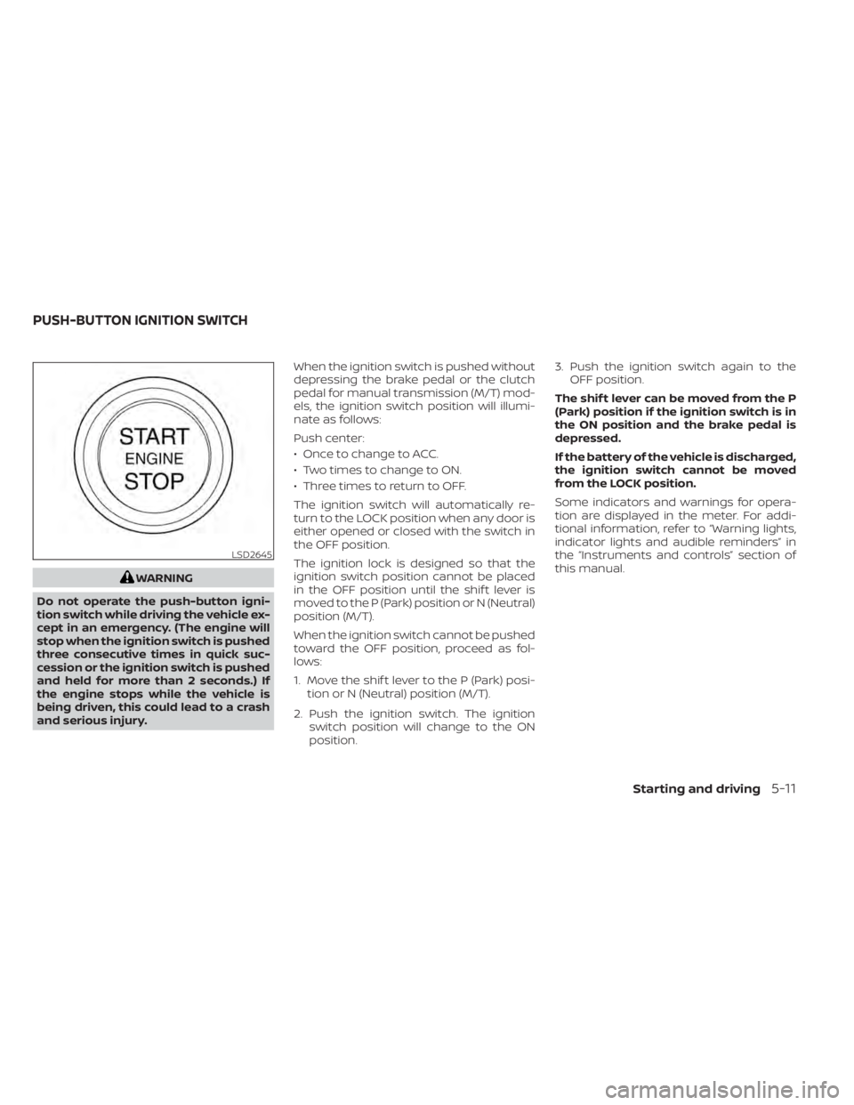
Do not operate the push-button igni-
tion switch while driving the vehicle ex-
cept in an emergency. (The engine will
stop when the ignition switch is pushed
three consecutive times in quick suc-
cession or the ignition switch is pushed
and held for more than 2 seconds.) If
the engine stops while the vehicle is
being driven, this could lead to a crash
and serious injury. When the ignition switch is pushed without
depressing the brake pedal or the clutch
pedal for manual transmission (M/T) mod-
els, the ignition switch position will illumi-
nate as follows:
Push center:
• Once to change to ACC.
• Two times to change to ON.
• Three times to return to OFF.
The ignition switch will automatically re-
turn to the LOCK position when any door is
either opened or closed with the switch in
the OFF position.
The ignition lock is designed so that the
ignition switch position cannot be placed
in the OFF position until the shif t lever is
moved to the P (Park) position or N (Neutral)
position (M/T).
When the ignition switch cannot be pushed
toward the OFF position, proceed as fol-
lows:
1. Move the shif t lever to the P (Park) posi-
tion or N (Neutral) position (M/T).
2. Push the ignition switch. The ignition switch position will change to the ON
position. 3. Push the ignition switch again to the
OFF position.
The shif t lever can be moved from the P
(Park) position if the ignition switch is in
the ON position and the brake pedal is
depressed.
If the battery of the vehicle is discharged,
the ignition switch cannot be moved
from the LOCK position.
Some indicators and warnings for opera-
tion are displayed in the meter. For addi-
tional information, refer to “Warning lights,
indicator lights and audible reminders” in
the “Instruments and controls” section of
this manual.
LSD2645
PUSH-BUTTON IGNITION SWITCH
Starting and driving5-11