Page 152 of 528
WARNING
Do not disassemble the horn. Doing so
could affect proper operation of the
supplemental front air bag system.
Tampering with the supplemental
front air bag system may result in seri-
ous personal injury.
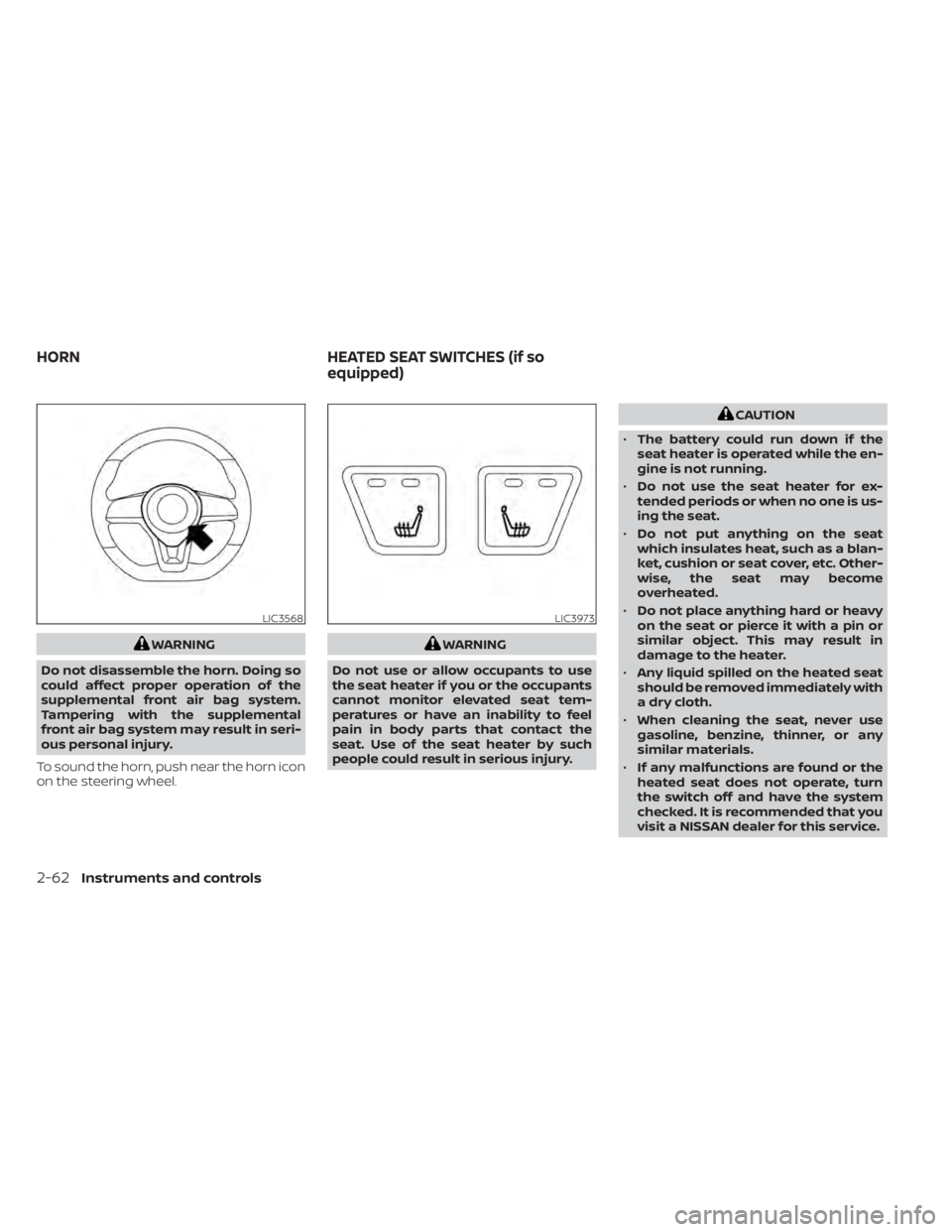
To sound the horn, push near the horn icon
on the steering wheel.
CAUTION
• The battery could run down if the
seat heater is operated while the en-
gine is not running.
• Do not use the seat heater for ex-
tended periods or when no one is us-
ing the seat.
• Do not put anything on the seat
which insulates heat, such as a blan-
ket, cushion or seat cover, etc. Other-
wise, the seat may become
overheated.
• Do not place anything hard or heavy
on the seat or pierce it with a pin or
similar object. This may result in
damage to the heater.
• Any liquid spilled on the heated seat
should be removed immediately with
a dry cloth.
• When cleaning the seat, never use
gasoline, benzine, thinner, or any
similar materials.
• If any malfunctions are found or the
heated seat does not operate, turn
the switch off and have the system
checked. It is recommended that you
visit a NISSAN dealer for this service.
LIC3973
HORN HEATED SEAT SWITCHES (if so
equipped)
Page 153 of 528
The front seats are warmed by built-in
heaters.
1. Start the engine.
2. To turn on, push the switch one time forthe LO position and one indicator light
will illuminate or twice for the HI position
and both indicators will illuminate.
The heater is controlled by a thermostat,
automatically turning the heater on and
off. The indicator light will remain on as
long as the switch is on.
3. When the seat is warmed or before you leave the vehicle, be sure to turn the
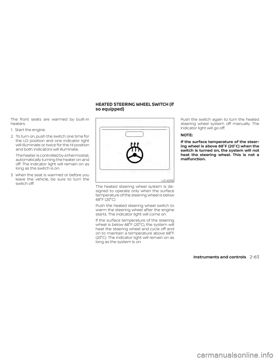
switch off. The heated steering wheel system is de-
signed to operate only when the surface
temperature of the steering wheel is below
68°F (20°C).
Push the heated steering wheel switch to
warm the steering wheel af ter the engine
starts. The indicator light will come on.
If the surface temperature of the steering
wheel is below 68°F (20°C), the system will
heat the steering wheel and cycle off and
on to maintain a temperature above 68°F
(20°C). The indicator light will remain on as
long as the system is on. Push the switch again to turn the heated
steering wheel system off manually. The
indicator light will go off.
NOTE:
If the surface temperature of the steer-
ing wheel is above 68°F (20°C) when the
switch is turned on, the system will not
heat the steering wheel. This is not a
malfunction.
Instruments and controls2-63
Page 197 of 528
To remove the fuel-filler cap:
1. Turn the fuel-filler cap counterclockwiseto remove.
2. Put the fuel-filler cap on the cap holder
O1while refueling.
To install the fuel-filler cap:
1. Insert the fuel-filler cap straight into the fuel-filler tube.
2. Turn the fuel-filler cap clockwise until a single click is heard.
LOOSE FUEL CAP warning
The LOOSE FUEL CAP warning appears in
the vehicle information display when the
fuel-filler cap is not tightened correctly af-
ter the vehicle has been refueled. It may
take a few driving trips for the message to
be displayed. To turn off the warning, do the
following:
1. Remove and install the fuel-filler cap aspreviously described as soon as
possible.
2. Tighten the fuel-filler cap until it clicks. 3. Press the OK button on the steering
wheel to turn off the Loose Fuel Cap
warning af ter tightening the fuel-filler
cap.
LPD3091LPD3029
Page 198 of 528
TILT OPERATION
Pull the lock lever downO1and adjust the
steering wheel up or down
O2to the de-
sired position.
Push the lock lever up
O1firmly lock the
steering wheel in place.
TELESCOPIC OPERATION
Pull the lock lever downO1and adjust the
steering wheel forward or backward
O3to
the desired position.
Push the lock lever up
O1firmly to lock the
steering wheel in place. 1. To block glare from the front, swing
down the main sun visor
O1.
2. To block glare from the side, remove the main sun visor from the center mount
and swing the visor to the side
O2. 3. To extend the sun visor, slide in or out as
needed
O3.
LPD2154
STEERING WHEEL SUN VISORS
Page 213 of 528
Vehicle width guide linesO4
Indicate the vehicle width when backing up.
Predicted course linesO5(if so equipped)
Indicate the predicted course when back-
ing up. The predicted course lines will be
displayed on the monitor when the shif t
lever is in the R (Reverse) position and the
steering wheel is turned. The predicted
course lines will move depending on how
much the steering wheel is turned and will
not be displayed while the steering wheel is
in the straight-ahead position.
The vehicle width guide lines and the width
of the predicted course lines are wider than
the actual width and course.
DIFFERENCE BETWEEN PREDICTED
AND ACTUAL DISTANCES
The displayed guidelines and their loca-
tions on the ground are for approximate
reference only. Objects on uphill or downhill
surfaces or projecting objects will be actu-
ally located at distances different from
those displayed in the monitor relative to
the guidelines (refer to illustrations). When
in doubt, turn around and view the objects
as you are backing up, or park and exit the
vehicle to view the positioning of objects
behind the vehicle.
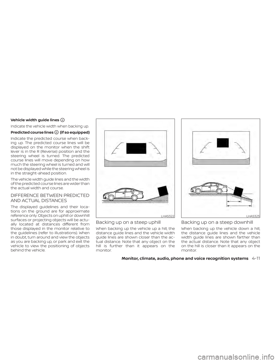
Backing up on a steep uphill
When backing up the vehicle up a hill, the
distance guide lines and the vehicle width
guide lines are shown closer than the ac-
tual distance. Note that any object on the
hill is further than it appears on the
monitor.
Backing up on a steep downhill
When backing up the vehicle down a hill,
the distance guide lines and the vehicle
width guide lines are shown farther than
the actual distance. Note that any object
on the hill is closer than it appears on the
monitor.
LHA5322LHA5323
Page 215 of 528
1. Visually check that the parking space issafe before parking your vehicle.
2. The rear view of the vehicle is displayed on the screen
OAwhen the shif t lever is
moved to the R (Reverse) position. 3. Slowly back up the vehicle adjusting the
steering wheel so that the predicted
course lines
OBenter the parking space
OC. 4. Maneuver the steering wheel to make
the vehicle width guide lines
ODparallel
to the parking space
OCwhile referring
to the predicted course lines.
5. When the vehicle is parked in the space completely, move the shif t lever to the P
(Park) position and apply the parking
brake.
LHA4769LHA4770
Page 221 of 528
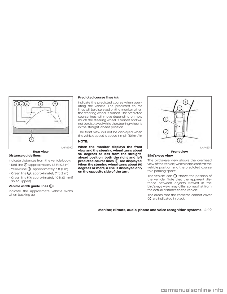
Distance guide lines:
Indicate distances from the vehicle body:
• Red line
O1: approximately 1.5 f t (0.5 m)
• Yellow line
O2: approximately 3 f t (1 m)
• Green line
O3: approximately 7 f t (2 m)
• Green line
O4: approximately 10 f t (3 m) (if
so equipped)
Vehicle width guide lines
O5:
Indicate the approximate vehicle width
when backing up. Predicted course lines
O6:
Indicate the predicted course when oper-
ating the vehicle. The predicted course
lines will be displayed on the monitor when
the steering wheel is turned. The predicted
course lines will move depending on how
much the steering wheel is turned and will
not be displayed while the steering wheel is
in the straight-ahead position.
The front view will not be displayed when
the vehicle speed is above 6 mph (10 km/h).
NOTE:
When the monitor displays the front
view and the steering wheel turns about
90 degrees or less from the straight-
ahead position, both the right and lef t
predicted course lines
O6are displayed.
When the steering wheel turns about 90
degrees or more, a line is displayed only
on the opposite side of the turn.
Bird’s-eye view
The bird's-eye view shows the overhead
view of the vehicle, which helps confirm the
vehicle position and the predicted course
to a parking space.
The vehicle icon
O1shows the position of
the vehicle. Note that the apparent dis-
tance between objects viewed in the
bird's-eye view may differ somewhat from
the actual distance to the vehicle.
The areas that the cameras cannot cover
O2are indicated in black.
LHA4992
Rear view
Monitor, climate, audio, phone and voice recognition systems4-19
Page 222 of 528
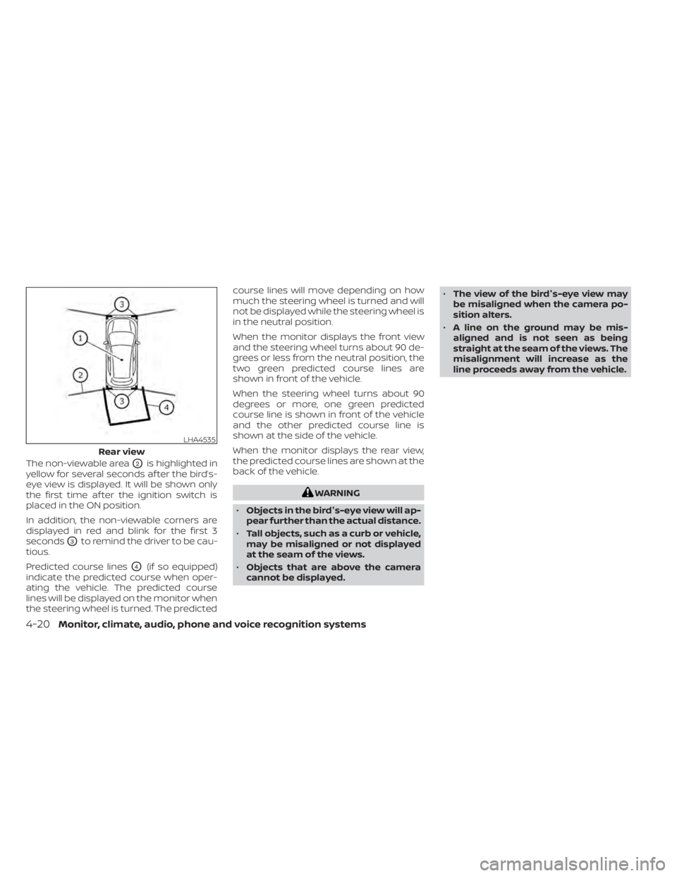
The non-viewable areaO2is highlighted in
yellow for several seconds af ter the bird’s-
eye view is displayed. It will be shown only
the first time af ter the ignition switch is
placed in the ON position.
In addition, the non-viewable corners are
displayed in red and blink for the first 3
seconds
O3to remind the driver to be cau-
tious.
Predicted course lines
O4(if so equipped)
indicate the predicted course when oper-
ating the vehicle. The predicted course
lines will be displayed on the monitor when
the steering wheel is turned. The predicted course lines will move depending on how
much the steering wheel is turned and will
not be displayed while the steering wheel is
in the neutral position.
When the monitor displays the front view
and the steering wheel turns about 90 de-
grees or less from the neutral position, the
two green predicted course lines are
shown in front of the vehicle.
When the steering wheel turns about 90
degrees or more, one green predicted
course line is shown in front of the vehicle
and the other predicted course line is
shown at the side of the vehicle.
When the monitor displays the rear view,
the predicted course lines are shown at the
back of the vehicle.