Page 395 of 528
System malfunction
If the Intelligent Driver Alertness system
malfunctions, the system warning mes-
sage will appear in the vehicle information
display and the function will be stopped
automatically.Action to take
Stop the vehicle in a safe location, place the
vehicle in P (Park) position, turn the engine
off and restart the engine. If the system
warning message continues to appear,
have the system checked. It is recom-
mended that you visit a NISSAN dealer for
this service.
LSD3802
BREAK-IN SCHEDULE
Starting and driving5-109
Page 398 of 528

WARNING
• Do not stop or park the vehicle over
flammable materials such as dry
grass, waste paper or rags. They may
ignite and cause a fire. •
Safe parking procedures require that
both the parking brake be set and the
transmission placed in P (Park) for
Continuously Variable Transmission
(CVT) models or in an appropriate
gear for manual transmission (M/T)
models. Failure to do so could cause
the vehicle to move unexpectedly or
roll away and result in an accident.
Make sure the shif t lever has been
pushed as far forward as it can go
and cannot be moved without de-
pressing the foot brake pedal.
• Never leave the engine running while
the vehicle is unattended. •
Do not leave children unattended in-
side the vehicle. They could unknow-
ingly activate switches or controls or
make the vehicle move. Unattended
children could become involved in
serious accidents.
• To help avoid risk of injury or death
through unintended operation of the
vehicle and/or its systems, do not
leave children, people who require
the assistance of others or pets unat-
tended in your vehicle. Additionally,
the temperature inside a closed ve-
hicle on a warm day can quickly be-
come high enough to cause a signifi-
cant risk of injury or death to people
and pets.
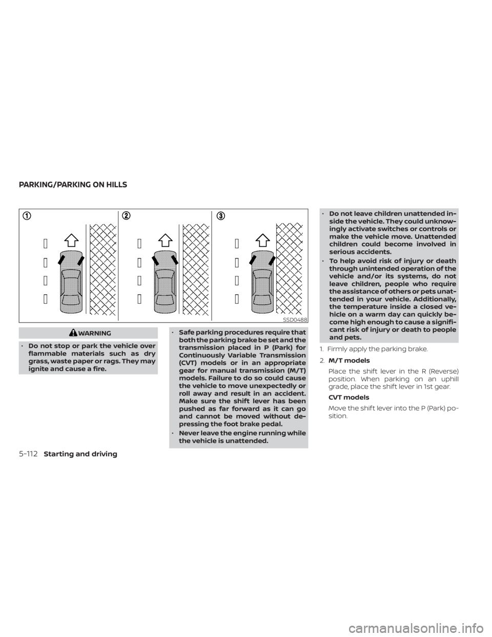
1. Firmly apply the parking brake.
2. M/T models
Place the shif t lever in the R (Reverse)
position. When parking on an uphill
grade, place the shif t lever in 1st gear.
CVT models
Move the shif t lever into the P (Park) po-
sition.
SSD0488
PARKING/PARKING ON HILLS
Page 402 of 528

BRAKE ASSIST
When the force applied to the brake pedal
exceeds a certain level, the Brake Assist is
activated generating greater braking force
than a conventional brake booster even
with light pedal force.indicator light in the instrument panel
flashes to note the following:
• The road may be slippery or the systemmay determine some action is required
to help keep the vehicle on the steered
path.
• You may feel a pulsation in the brake pedal and hear a noise or vibration from
under the hood. This is normal and indi-
cates that the VDC system is working
properly.
• Adjust your speed and driving to the road conditions.
For additional information, refer to “Slip in-
dicator light” and ”Vehicle Dynamic Control
(VDC) OFF indicator light” in the ”Instru-
ments and controls” section of this manual.
If a malfunction occurs in the system, the
indicator light comes on in the instru-
ment panel. The VDC system automatically
turns off when the indicator light is off.
The vehicle information display is used to
turn off the VDC system. The
indicator
light and the AEB system warning light illu-
minates to indicate the VDC system is off.
VEHICLE DYNAMIC CONTROL (VDC)
SYSTEM
5-116Starting and driving
Page 416 of 528
Push the switch on to warn other drivers
when you must stop or park under emer-
gency conditions. All turn signal lights flash.
LIC0394
HAZARD WARNING FLASHER SWITCHEMERGENCY ENGINE SHUT OFF
Page 417 of 528
TIRE PRESSURE MONITORING
SYSTEM (TPMS)
This vehicle is equipped with TPMS. It moni-
tors tire pressure of all tires except the
spare. When the low tire pressure warning
light is lit, and the “CHECK TIRE PRES” (ve-
hicles without a vehicle information dis-
play) also appears in the trip computer or
the “Tire Pressure Low - Add Air” (vehicles
with a vehicle information display) appears
in the vehicle information display, one or
more of your tires is significantly under-
inflated. If the vehicle is being driven with
low tire pressure, the TPMS will activate and
warn you of it by the low tire pressure warn-
ing light. This system will activate only
when the vehicle is driven at speeds above
16 mph (25 km/h). For additional informa-
tion, refer to “Warning lights, indicator lights
and audible reminders” in the “Instruments
and controls” section, and “Tire Pressure
Monitoring System (TPMS)” in the “Starting
and driving” sections of this manual.
Page 418 of 528
CHANGING A FLAT TIRE
If you have a flat tire, follow the instructions
below:
Stopping the vehicle
1. Safely move the vehicle off the road andaway from traffic.
2. Turn on the hazard warning flashers.
3. Park on a level surface and apply the parking brake. Shif t the manual trans-
mission into R (Reverse), or the CVT into
P (Park).
4. Turn off the engine.
5. Raise the hood to warn other traffic and to signal professional road assistance
personnel that you need assistance.
6. Have all passengers get out of the ve- hicle and stand in a safe place, away
from traffic and clear of the vehicle.
6-4In case of emergency
Page 423 of 528
WARNING
• Always make sure that the spare tire
and jacking equipment are properly
secured af ter use. Such items can be-
come dangerous projectiles in an ac-
cident or sudden stop.
• The spare tire is designed for emer-
gency use. Refer to specific instruc-
tions under the heading “Wheels and
tires” in the “Do-it-yourself ” section
of this manual. To start your engine with a booster battery,
the instructions and precautions below
must be followed.
Page 424 of 528
WARNING
Always follow the instructions below.
Failure to do so could result in damage
to the charging system and cause per-
sonal injury.
1. If the booster battery is in another ve- hicle, position the two vehicles to bring
their batteries near each other.
Do not allow the two vehicles to touch. 2. Apply the parking brake. Move the shif t
lever to N (Neutral) (manual transmis-
sion) or to P (Park) (Continuously Variable
Transmission (CVT)). Switch off all un-
necessary electrical systems (lights,
heater, air conditioner, etc.).
3. Place the ignition switch to the LOCK or OFF position.
4. Connect the jumper cables in the se- quence illustrated (
OA,OB,OC,OD).
LCE2223
6-10In case of emergency