2022 NISSAN ROGUE SPORT instrument panel
[x] Cancel search: instrument panelPage 147 of 508
system.
. The ECO mode system will turn off
automatically if a malfunction occurs
in the system.
. Turn off the ECO mode system when
acceleration is required such as when:
— driving with a heavy load of pas-
sengers or cargo in the vehicle
— driving on a steep uphill slope
WAC0077X
Instrument Panel
WAC0233XCenter Console Box
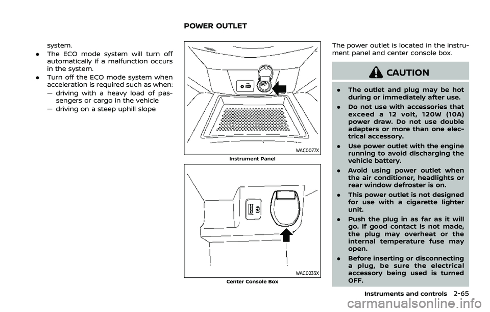
The power outlet is located in the instru-
ment panel and center console box.
CAUTION
. The outlet and plug may be hot
during or immediately after use.
. Do not use with accessories that
exceed a 12 volt, 120W (10A)
power draw. Do not use double
adapters or more than one elec-
trical accessory.
. Use power outlet with the engine
running to avoid discharging the
vehicle battery.
. Avoid using power outlet when
the air conditioner, headlights or
rear window defroster is on.
. This power outlet is not designed
for use with a cigarette lighter
unit.
. Push the plug in as far as it will
go. If good contact is not made,
the plug may overheat or the
internal temperature fuse may
open.
. Before inserting or disconnecting
a plug, be sure the electrical
accessory being used is turned
OFF.
Instruments and controls2-65
POWER OUTLET
Page 149 of 508
EMERGENCY SUPPORT
NissanConnect® Services provides var-
ious services to support dealing with
emergencies of the subscribed vehicle
and the driver.
For example, in case of an illness or
serious injury, you can seek support by
pushing the in-vehicle Emergency Call
(SOS) button and connecting to Nissan-
Connect® Services. NissanConnect® Ser-
vices can specify the location of the
vehicle via GPS, and the information will
be sent to the police or other agencies as
needed.
For information about other NissanCon-
nect® Services emergency support re-
lated services, refer to the
NissanConnect® Services website or con-
tact the NissanConnect® Customer Sup-
port Line.
NissanConnect® Services website:
For U.S.
www.nissanusa.com/connect
For Canada
http://www.nissan.ca/nissanconnect
(English)
www.nissan.ca/nissanconnect/fr
(French)NissanConnect® Customer Support Line:
1-855-426-6628
WARNING
.
Please note that the Automatic
Collision Notification service and
Emergency Call function cannot
be used in the following condi-
tions:
— Emergency functions and ser-
vices will not be available
without a paid subscription
to NissanConnect® Services.
— The NissanConnect® Services network system is disabled.
— The vehicle moves outside the service area where the TCU
(Telematics Control Unit) is
connected to the system.
— The vehicle is outside the area where the cellular network
service is receivable.
— The vehicle is in a location with poor signal reception
such as tunnels, underground
parking garages, behind
buildings or in mountainous
areas. — The line is busy.
— The TCU (Telematics Control
Unit) or other systems of your
vehicle are not working prop-
erly.
— It may not be possible to make an emergency call de-
pending on the severity of a
collision and/or emergency.
. Park the vehicle in a safe location
and set the parking brake before
operating the Emergency Call
(SOS) button.
. Only use this service in case of an
emergency. There may be a pen-
alty for inappropriate use of the
service.
. Radio waves could adversely af-
fect electric medical equipment.
Individuals who use pacemakers
should contact the device manu-
facturer regarding any possible
effects before using the system.
. The TCU (Telematics Control Unit)
antenna is installed inside the
upper central part of the instru-
ment panel. An occupant should
not get any closer to the antenna
than specified by the pacemaker
manufacturer. The radio waves
Instruments and controls2-67
EMERGENCY CALL (SOS) BUTTON
(if so equipped)
Page 196 of 508
3-26Pre-driving checks and adjustments
WAD0090X
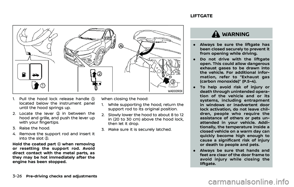
1. Pull the hood lock release handlelocated below the instrument panel
until the hood springs up.
2. Locate the lever
in between the
hood and grille, and push the lever up
with your fingertips.
3. Raise the hood.
4. Remove the support rod and insert it into the slot
.
Hold the coated part
when removing
or resetting the support rod. Avoid
direct contact with the metal parts, as
they may be hot immediately after the
engine has been stopped. When closing the hood:
1. While supporting the hood, return the
support rod to its original position.
2. Slowly lower the hood to about 8 to 12 in (20 to 30 cm) above the hood lock,
then let it drop.
3. Make sure it is securely latched.
WARNING
. Always be sure the liftgate has
been closed securely to prevent it
from opening while driving.
. Do not drive with the liftgate
open. This could allow dangerous
exhaust gases to be drawn into
the vehicle. For additional infor-
mation, refer to “Exhaust gas
(carbon monoxide)” (P.5-4).
. To help avoid risk of injury or
death through unintended opera-
tion of the vehicle and or its
systems, including entrapment
in windows or inadvertent door
lock activation, do not leave chil-
dren, people who require the
assistance of others or pets un-
attended in your vehicle. Addi-
tionally, the temperature inside a
closed vehicle on a warm day can
quickly become high enough to
cause a significant risk of injury
or death to people and pets.
. Always be sure that hands and
feet are clear of the door frame to
avoid injury while closing the
liftgate.
LIFTGATE
Page 217 of 508
viewed. The four corners of the
vehicle in particular, are areas
where objects do not always ap-
pear in the bird’s-eye, front, or
rear views. Always check your
surroundings to be sure that it is
safe to move before operating
the vehicle. Always operate the
vehicle slowly.
. The driver is always responsible
for safety during parking and
other maneuvers.
CAUTION
Do not scratch the lens when clean-
ing dirt or snow from the front of the
camera.
The Intelligent Around View® Monitor
system is designed as an aid to the driver
in situations such as slot parking or
parallel parking.
The monitor displays various views of the
position of the vehicle in a split screen
format. Not all views are available at all
times. Available views:
.
Front view
The view to the front of the vehicle.
. Rear view
The view to the rear of the vehicle.
. Bird’s-eye view
The views to the vehicle from above.
. Front-side view
The view around and ahead of the
front passenger’s side wheel.
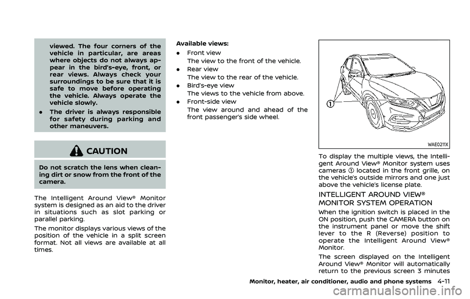
WAE0211X
To display the multiple views, the Intelli-
gent Around View® Monitor system uses
cameras
located in the front grille, on
the vehicle’s outside mirrors and one just
above the vehicle’s license plate.
INTELLIGENT AROUND VIEW®
MONITOR SYSTEM OPERATION
When the ignition switch is placed in the
ON position, push the CAMERA button on
the instrument panel or move the shift
lever to the R (Reverse) position to
operate the Intelligent Around View®
Monitor.
The screen displayed on the Intelligent
Around View® Monitor will automatically
return to the previous screen 3 minutes
Monitor, heater, air conditioner, audio and phone systems4-11
Page 239 of 508
OPERATING TIPS (for automatic air
conditioner)
When the engine coolant temperature
and outside air temperature are low, the
air flow from the foot outlets may not
operate for a maximum of 150 seconds.
However, this is not a malfunction. After
the coolant temperature warms up, air
flow from the foot outlets will operate
normally.
The sensors
and, located on the
instrument panel, help maintain a con-
stant temperature. Do not put anything
on or around the sensors.
SERVICING AIR CONDITIONER
WARNING
The air conditioner system contains
refrigerant under high pressure. To
avoid personal injury, any air condi-
tioner service should be done only by
an experienced technician with the
proper equipment.
The air conditioner system in your vehicle
is charged with a refrigerant designed
with the environment in mind.
This refrigerant will not harm the
earth’s ozone layer. However, it maycontribute in a small part to global
warming.
Special charging equipment and lubricant
are required when servicing your vehicle’s
air conditioner. Using improper refriger-
ants or lubricants will cause severe da-
mage to the air conditioner system. (See
“Air conditioning system refrigerant and
oil recommendations” (P.10-6).)
A NISSAN dealer will be able to service
your environmentally friendly air condi-
tioner system.
In-cabin microfilter
The air conditioner system is equipped
with an in-cabin microfilter. To make sure
the air conditioner heats, defogs, and
ventilates efficiently, replace the filter
according to the specified maintenance
intervals listed in the "9. Maintenance and
schedules" section. It is recommended to
visit a NISSAN dealer to replace the filter.
The filter should be replaced if the air flow
decreases significantly or if windows fog
up easily when operating the heater or air
conditioner.SAA2374
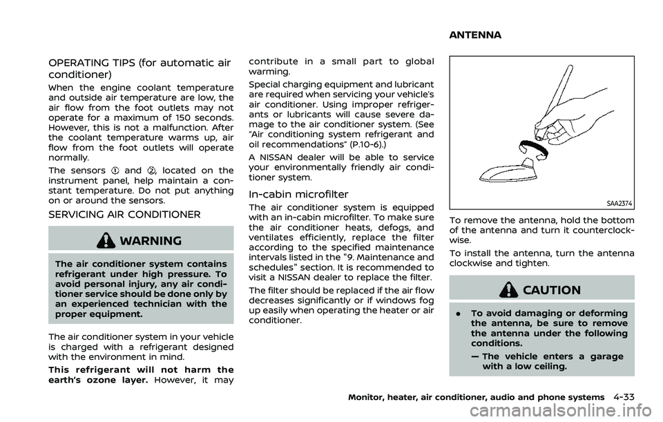
To remove the antenna, hold the bottom
of the antenna and turn it counterclock-
wise.
To install the antenna, turn the antenna
clockwise and tighten.
CAUTION
.
To avoid damaging or deforming
the antenna, be sure to remove
the antenna under the following
conditions.
— The vehicle enters a garage
with a low ceiling.
Monitor, heater, air conditioner, audio and phone systems4-33
ANTENNA
Page 255 of 508
start the engine.
.The cargo room area is not included in
the operating range but the Intelligent
Key may function.
. If the Intelligent Key is placed on the
instrument panel, inside the glove box
or door pocket, the Intelligent Key may
not function.
. If the Intelligent Key is placed near the
door or window outside the vehicle,
the Intelligent Key may function.
PUSH-BUTTON IGNITION SWITCH
OPERATION
CAUTION
.Do not leave the vehicle for ex-
tended periods of time when the
ignition switch is in the ON posi-
tion and the engine is not run-
ning. This can discharge the
battery.
. Use electrical accessories with
the engine running to avoid dis-
charging the vehicle battery. If
you must use accessories while
the engine is not running, do not
use them for extended periods of
time and do not use multiple
electrical accessories at the same time.
JVS0937X
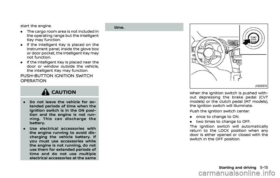
When the ignition switch is pushed with-
out depressing the brake pedal (CVT
models) or the clutch pedal (MT models),
the ignition switch will illuminate.
Push the ignition switch center:
.
once to change to ON.
. two times to change to OFF.
The ignition switch will automatically
return to the LOCK position when any
door is either opened or closed with the
switch in the OFF position.
Starting and driving5-15
Page 272 of 508
5-32Starting and driving
applied and the brake force of the
automatic brake hold will be re-
leased:
—The braking force is applied by
the automatic brake hold function
for 3 minutes or longer.
— The driver’s seat belt is unfas-
tened.
— The ignition switch is placed in
the OFF position.
— If a malfunction occurs in the
automatic brake hold function.
. When the vehicle stops, but the
brake force is not automatically
applied, depress the brake pedal
firmly until the automatic brake hold
indicator light (green) illuminates.
Automatic brake hold function dis-
play
The automatic brake hold function status
can be checked in the “Chassis Control”
mode in the vehicle information display.
For additional information, see “Trip com-
puter” (P.2-40).
WAF0037X
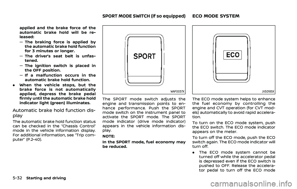
The SPORT mode switch adjusts the
engine and transmission points to en-
hance performance. Push the SPORT
mode switch on the instrument panel to
activate the SPORT mode. The SPORT
mode indicator (drive mode indicator)
appears in the vehicle information dis-
play.
NOTE:
In the SPORT mode, fuel economy may
be reduced.
JVS0185X
The ECO mode system helps to enhance
the fuel economy by controlling the
engine and CVT operation (for CVT mod-
els) automatically to avoid rapid accelera-
tion.
To turn on the ECO mode system, push
the ECO switch. The ECO mode indicator
appears on the meter.
To turn off the ECO mode, push the ECO
switch again. The ECO mode indicator will
turn off.
.The ECO mode system cannot be
turned off while the accelerator pedal
is depressed even if the ECO switch is
pushed to OFF. Release the accelera-
tor pedal to turn off the ECO mode
SPORT MODE SWITCH (if so equipped)ECO MODE SYSTEM
Page 279 of 508
the LDW system will resume operating
automatically and the LDW indicator will
stop flashing.
Condition B:
The warning function of the LDW system
is not designed to work under the follow-
ing conditions:
.When you operate the lane change
signal and change traveling lanes in
the direction of the signal. (The LDW
system will become operable again
approximately 2 seconds after the
lane change signal is turned off.)
. When the vehicle speed lowers to less
than approximately 37 MPH (60 km/h).
Action to take:
After the above conditions have finished
and the necessary operating conditions
are satisfied, the LDW system will resume.SYSTEM MALFUNCTION
If the LDW system malfunctions, it will
cancel automatically and “Malfunction”
will appear in the vehicle information
display. If the warning message appears
in the vehicle information display, pull off
the road to a safe location and stop the
vehicle. Place the ignition switch in the
OFF position and restart the engine. If the
warning message continues to appear in
the vehicle information display, have the
system checked. It is recommended that
you visit a NISSAN dealer for this service.
WAC0198X
SYSTEM MAINTENANCE
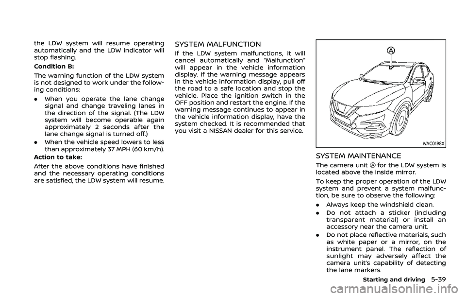
The camera unitfor the LDW system is
located above the inside mirror.
To keep the proper operation of the LDW
system and prevent a system malfunc-
tion, be sure to observe the following:
. Always keep the windshield clean.
. Do not attach a sticker (including
transparent material) or install an
accessory near the camera unit.
. Do not place reflective materials, such
as white paper or a mirror, on the
instrument panel. The reflection of
sunlight may adversely affect the
camera unit’s capability of detecting
the lane markers.
Starting and driving5-39