2022 NISSAN ROGUE SPORT lock
[x] Cancel search: lockPage 198 of 508
3-28Pre-driving checks and adjustments
WARNING
.Fuel is extremely flammable and
highly explosive under certain
conditions. You could be burned
or seriously injured if it is misused
or mishandled. Always stop the
engine and do not smoke or allow
open flames or sparks near the
vehicle when refueling.
. Fuel may be under pressure. Turn
the cap a half of a turn, and wait
for any “hissing” sound to stop to
prevent fuel from spraying out
and possibly causing personal
injury. Then remove the cap.
. Use only an original equipment
type fuel-filler cap as a replace-
ment. It has a built-in safety valve
needed for proper operation of
the fuel system and emission
control system. An incorrect cap
can result in a serious malfunc-
tion and possible injury.
JVP0540X
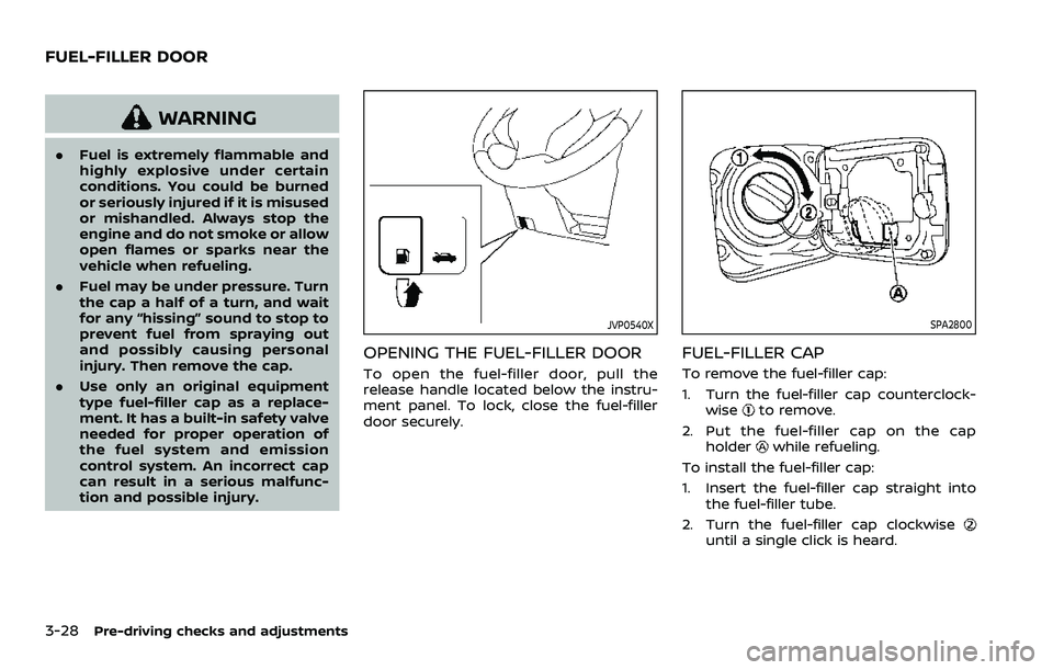
OPENING THE FUEL-FILLER DOOR
To open the fuel-filler door, pull the
release handle located below the instru-
ment panel. To lock, close the fuel-filler
door securely.
SPA2800
FUEL-FILLER CAP
To remove the fuel-filler cap:
1. Turn the fuel-filler cap counterclock-
wise
to remove.
2. Put the fuel-filler cap on the cap holder
while refueling.
To install the fuel-filler cap:
1. Insert the fuel-filler cap straight into the fuel-filler tube.
2. Turn the fuel-filler cap clockwise
until a single click is heard.
FUEL-FILLER DOOR
Page 201 of 508
JVP0301X
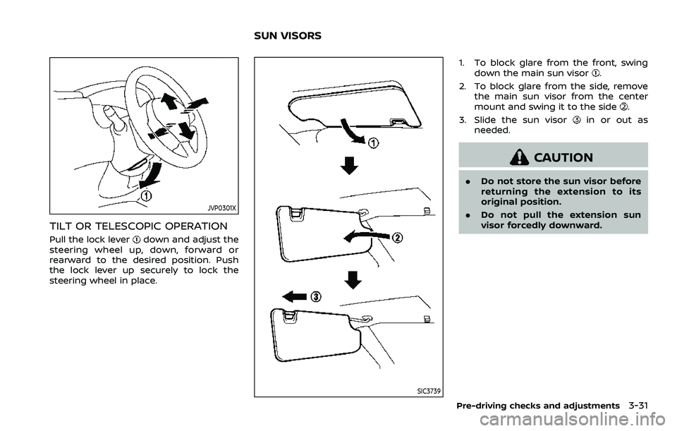
TILT OR TELESCOPIC OPERATION
Pull the lock leverdown and adjust the
steering wheel up, down, forward or
rearward to the desired position. Push
the lock lever up securely to lock the
steering wheel in place.
SIC3739
1. To block glare from the front, swing down the main sun visor.
2. To block glare from the side, remove the main sun visor from the center
mount and swing it to the side
.
3. Slide the sun visor
in or out as
needed.
CAUTION
. Do not store the sun visor before
returning the extension to its
original position.
. Do not pull the extension sun
visor forcedly downward.
Pre-driving checks and adjustments3-31
SUN VISORS
Page 212 of 508
4-6Monitor, heater, air conditioner, audio and phone systems
SAA1980
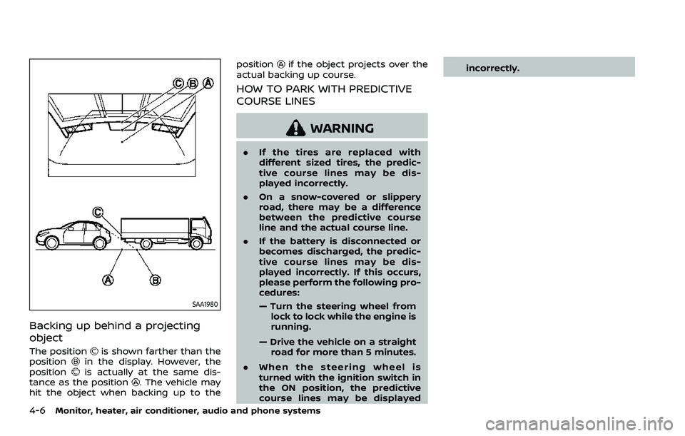
Backing up behind a projecting
object
The positionis shown farther than the
positionin the display. However, the
positionis actually at the same dis-
tance as the position. The vehicle may
hit the object when backing up to the position
if the object projects over the
actual backing up course.
HOW TO PARK WITH PREDICTIVE
COURSE LINES
WARNING
. If the tires are replaced with
different sized tires, the predic-
tive course lines may be dis-
played incorrectly.
. On a snow-covered or slippery
road, there may be a difference
between the predictive course
line and the actual course line.
. If the battery is disconnected or
becomes discharged, the predic-
tive course lines may be dis-
played incorrectly. If this occurs,
please perform the following pro-
cedures:
— Turn the steering wheel from
lock to lock while the engine is
running.
— Drive the vehicle on a straight road for more than 5 minutes.
. When the steering wheel is
turned with the ignition switch in
the ON position, the predictive
course lines may be displayed incorrectly.
Page 222 of 508
4-16Monitor, heater, air conditioner, audio and phone systems
SAA3475
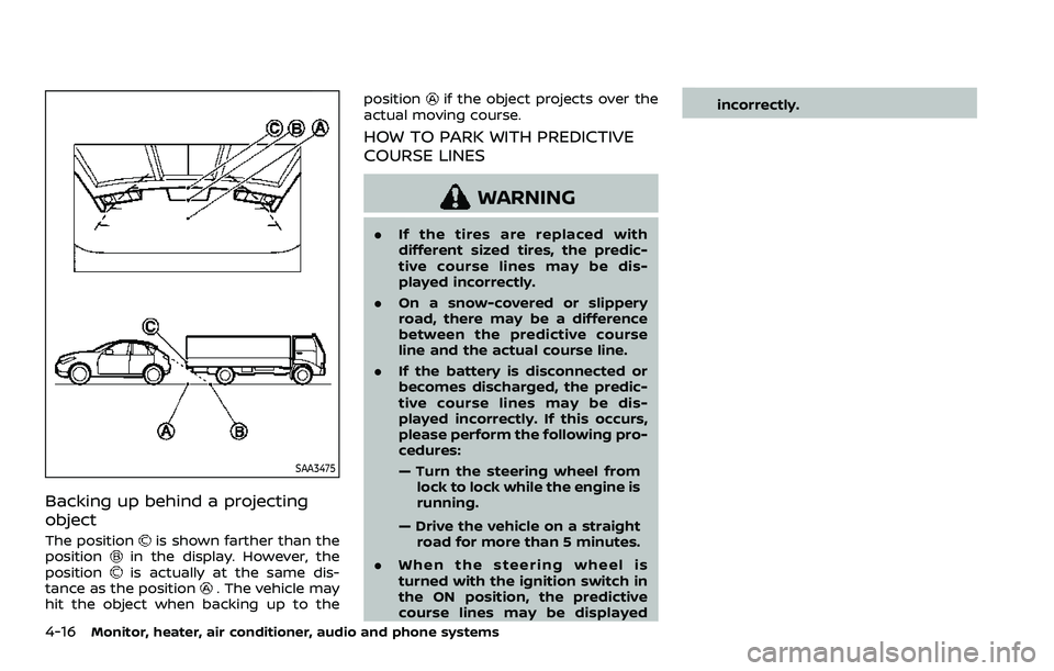
Backing up behind a projecting
object
The positionis shown farther than the
positionin the display. However, the
positionis actually at the same dis-
tance as the position. The vehicle may
hit the object when backing up to the position
if the object projects over the
actual moving course.
HOW TO PARK WITH PREDICTIVE
COURSE LINES
WARNING
. If the tires are replaced with
different sized tires, the predic-
tive course lines may be dis-
played incorrectly.
. On a snow-covered or slippery
road, there may be a difference
between the predictive course
line and the actual course line.
. If the battery is disconnected or
becomes discharged, the predic-
tive course lines may be dis-
played incorrectly. If this occurs,
please perform the following pro-
cedures:
— Turn the steering wheel from
lock to lock while the engine is
running.
— Drive the vehicle on a straight road for more than 5 minutes.
. When the steering wheel is
turned with the ignition switch in
the ON position, the predictive
course lines may be displayed incorrectly.
Page 230 of 508
4-24Monitor, heater, air conditioner, audio and phone systems
may not be heard.
. The MOD system performance
will be limited according to en-
vironmental conditions and sur-
rounding objects such as:
— When there is low contrast
between background and the
moving objects.
— When there is blinking source of light.
— When strong light such as another vehicle’s headlight or
sunlight is present.
— When camera orientation is not in its usual position, such
as when the outside mirror is
folded.
— When there is dirt, water drops or snow on the camera lens.
— When the position of the mov- ing objects in the display is
not changed.
. The MOD system might detect
flowing water droplets on the
camera lens, white smoke from
the muffler, moving shadows, etc.
. The MOD system may not func-
tion properly depending on the
speed, direction, distance or shape of the moving objects.
. If your vehicle sustains damage
to the parts where the camera is
installed, leaving it misaligned or
bent, the sensing zone may be
altered and the MOD system may
not detect objects properly.
. When the temperature is extre-
mely high or low, the screen may
not display objects clearly. This is
not a malfunction.
NOTE:
The blue MOD icon will change to
orange if one of the following has
occurred.
. When the system is malfunctioning.
. When the component temperature
reaches a high level (icon will blink).
. When the rear view camera has
detected a blockage (icon will blink).
If the icon light continues to illuminate
orange, have the MOD system checked.
It is recommended that you visit a
NISSAN dealer for this service.
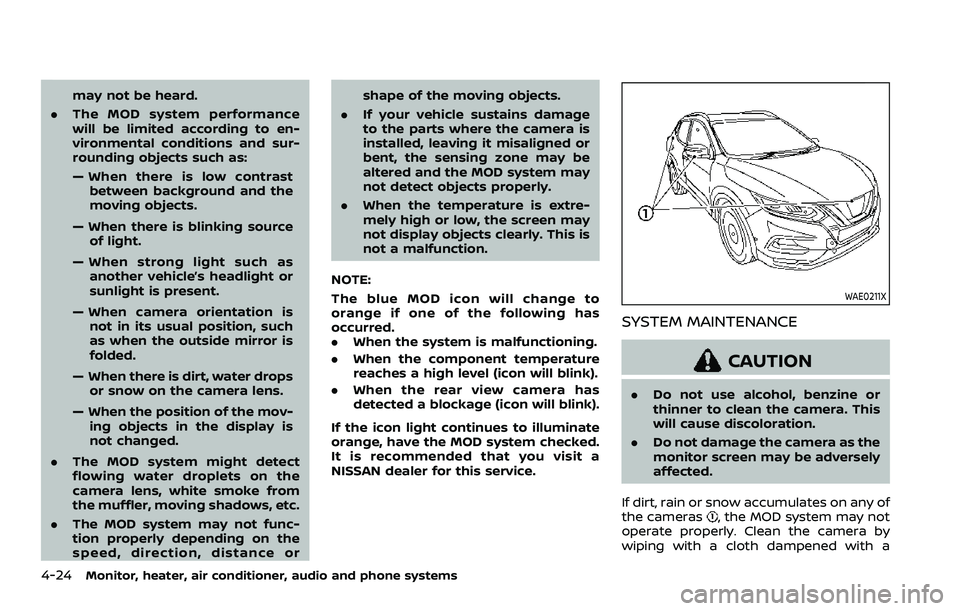
WAE0211X
SYSTEM MAINTENANCE
CAUTION
. Do not use alcohol, benzine or
thinner to clean the camera. This
will cause discoloration.
. Do not damage the camera as the
monitor screen may be adversely
affected.
If dirt, rain or snow accumulates on any of
the cameras
, the MOD system may not
operate properly. Clean the camera by
wiping with a cloth dampened with a
Page 233 of 508
JVH0664X
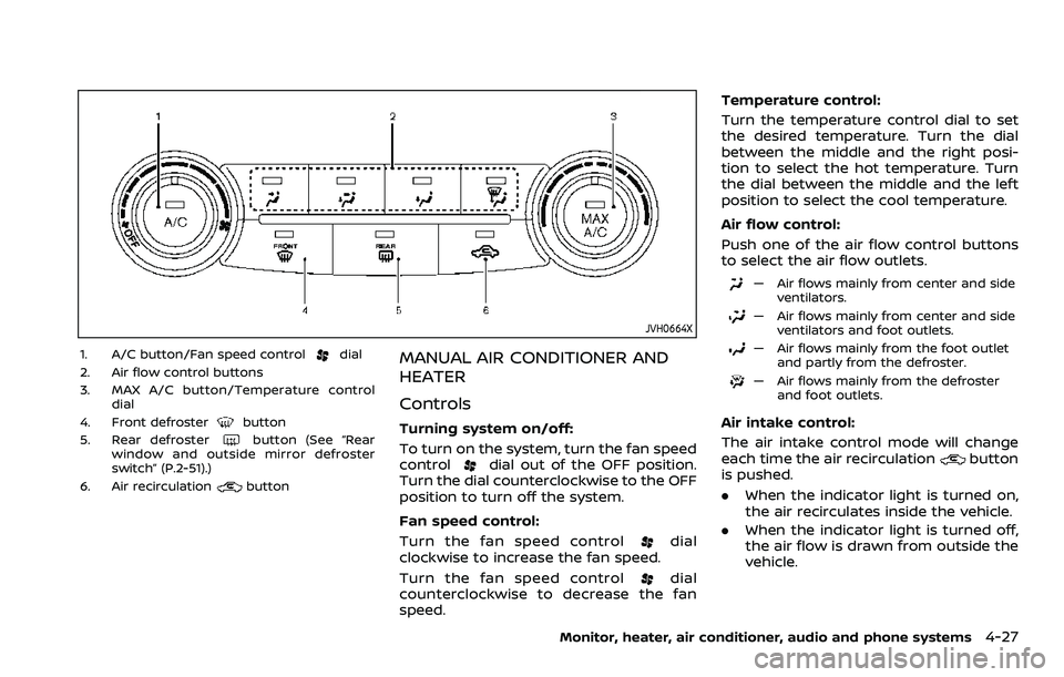
1. A/C button/Fan speed controldial
2. Air flow control buttons
3. MAX A/C button/Temperature control dial
4. Front defroster
button
5. Rear defrosterbutton (See “Rear
window and outside mirror defroster
switch” (P.2-51).)
6. Air recirculation
button
MANUAL AIR CONDITIONER AND
HEATER
Controls
Turning system on/off:
To turn on the system, turn the fan speed
control
dial out of the OFF position.
Turn the dial counterclockwise to the OFF
position to turn off the system.
Fan speed control:
Turn the fan speed control
dial
clockwise to increase the fan speed.
Turn the fan speed control
dial
counterclockwise to decrease the fan
speed. Temperature control:
Turn the temperature control dial to set
the desired temperature. Turn the dial
between the middle and the right posi-
tion to select the hot temperature. Turn
the dial between the middle and the left
position to select the cool temperature.
Air flow control:
Push one of the air flow control buttons
to select the air flow outlets.
— Air flows mainly from center and side
ventilators.
— Air flows mainly from center and sideventilators and foot outlets.
— Air flows mainly from the foot outletand partly from the defroster.
— Air flows mainly from the defrosterand foot outlets.
Air intake control:
The air intake control mode will change
each time the air recirculation
button
is pushed.
. When the indicator light is turned on,
the air recirculates inside the vehicle.
. When the indicator light is turned off,
the air flow is drawn from outside the
vehicle.
Monitor, heater, air conditioner, audio and phone systems4-27
Page 239 of 508
OPERATING TIPS (for automatic air
conditioner)
When the engine coolant temperature
and outside air temperature are low, the
air flow from the foot outlets may not
operate for a maximum of 150 seconds.
However, this is not a malfunction. After
the coolant temperature warms up, air
flow from the foot outlets will operate
normally.
The sensors
and, located on the
instrument panel, help maintain a con-
stant temperature. Do not put anything
on or around the sensors.
SERVICING AIR CONDITIONER
WARNING
The air conditioner system contains
refrigerant under high pressure. To
avoid personal injury, any air condi-
tioner service should be done only by
an experienced technician with the
proper equipment.
The air conditioner system in your vehicle
is charged with a refrigerant designed
with the environment in mind.
This refrigerant will not harm the
earth’s ozone layer. However, it maycontribute in a small part to global
warming.
Special charging equipment and lubricant
are required when servicing your vehicle’s
air conditioner. Using improper refriger-
ants or lubricants will cause severe da-
mage to the air conditioner system. (See
“Air conditioning system refrigerant and
oil recommendations” (P.10-6).)
A NISSAN dealer will be able to service
your environmentally friendly air condi-
tioner system.
In-cabin microfilter
The air conditioner system is equipped
with an in-cabin microfilter. To make sure
the air conditioner heats, defogs, and
ventilates efficiently, replace the filter
according to the specified maintenance
intervals listed in the "9. Maintenance and
schedules" section. It is recommended to
visit a NISSAN dealer to replace the filter.
The filter should be replaced if the air flow
decreases significantly or if windows fog
up easily when operating the heater or air
conditioner.SAA2374
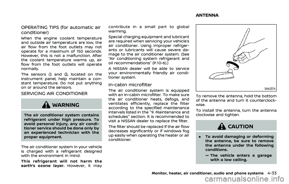
To remove the antenna, hold the bottom
of the antenna and turn it counterclock-
wise.
To install the antenna, turn the antenna
clockwise and tighten.
CAUTION
.
To avoid damaging or deforming
the antenna, be sure to remove
the antenna under the following
conditions.
— The vehicle enters a garage
with a low ceiling.
Monitor, heater, air conditioner, audio and phone systems4-33
ANTENNA
Page 240 of 508
4-34Monitor, heater, air conditioner, audio and phone systems
— The vehicle is covered with acar cover.
. Be sure that antenna is removed
before the vehicle enters an auto-
matic car wash.
. Always properly tighten the an-
tenna rod during installation.
Otherwise, the antenna rod may
break during vehicle operation.
. A build up of ice on the antenna
can affect radio performance. Re-
move the ice to restore radio
reception.
. When removing snow from the
roof, do not apply strong force to
the antenna. That may cause
broken antenna and roof panel
dent.
. When using a high pressure car
wash, keep the high pressure
nozzle away from the antenna.
The seal may be deformed or
damaged.
. The radio performance may be
affected if cargo carried on the
roof blocks the radio signal. If
possible, do not put cargo near
the antenna.When installing a car phone or a CB radio
in your vehicle, be sure to observe the
following precautions, otherwise the new
equipment may adversely affect the elec-
tronic control modules and electronic
control system harness.
WARNING
.A cellular phone should not be
used for any purpose while driv-
ing so full attention may be given
to vehicle operation. Some juris-
dictions prohibit the use of cellu-
lar phones while driving.
. If you must make a call while your
vehicle is in motion, the hands-
free cellular phone operational
mode (if so equipped) is highly
recommended. Exercise extreme
caution at all times so full atten-
tion may be given to vehicle
operation.
. If a conversation in a moving
vehicle requires you to take
notes, pull off the road to a safe
location and stop your vehicle
before doing so.
CAUTION
.Keep the antenna as far away as
possible from the electronic con-
trol modules.
. Keep the antenna wire more than
8 in (20 cm) away from the
electronic control system har-
ness. Do not route the antenna
wire next to any harness.
. Adjust the antenna standing-
wave ratio as recommended by
the manufacturer.
. Connect the ground wire from the
CB radio chassis to the body.
. For details, it is recommended
you visit a NISSAN dealer.
CAR PHONE OR CB RADIO