Page 114 of 508

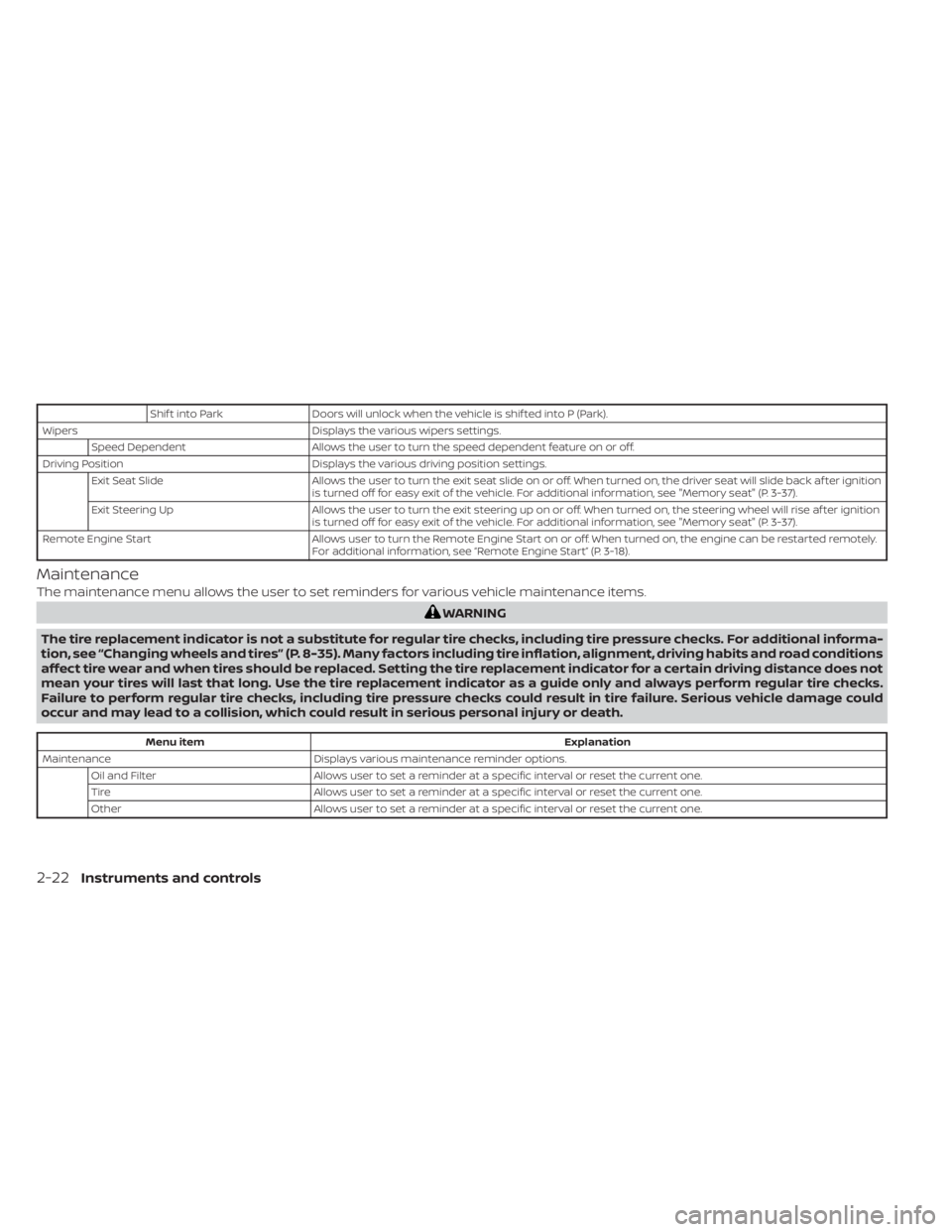
Shif t into ParkDoors will unlock when the vehicle is shif ted into P (Park).
Wipers Displays the various wipers settings.
Speed Dependent Allows the user to turn the speed dependent feature on or off.
Driving Position Displays the various driving position settings.
Exit Seat Slide Allows the user to turn the exit seat slide on or off. When turned on, the driver seat will slide back af ter ignition
is turned off for easy exit of the vehicle. For additional information, see "Memory seat" (P. 3-37).
Exit Steering Up Allows the user to turn the exit steering up on or off. When turned on, the steering wheel will rise af ter ignition
is turned off for easy exit of the vehicle. For additional information, see "Memory seat" (P. 3-37).
Remote Engine Start Allows user to turn the Remote Engine Start on or off. When turned on, the engine can be restarted remotely.
For additional information, see “Remote Engine Start” (P. 3-18).
Maintenance
The maintenance menu allows the user to set reminders for various vehicle maintenance items.
Menu item Explanation
Maintenance Displays various maintenance reminder options.
Oil and Filter Allows user to set a reminder at a specific interval or reset the current one.
Tire Allows user to set a reminder at a specific interval or reset the current one.
Other Allows user to set a reminder at a specific interval or reset the current one.
2-22Instruments and controls
Page 119 of 508
cruise
control switch on the steering wheel is
pressed and Cruise Control Alerts are en-
abled in the vehicle information display.
For additional information, see “Cruise con-
trol” (P. 5-55).
Cruise Target Speed SET
This message will appear if the Cruise Con-
trol system is on when the SET switch is
pushed and the Cruise Control Alerts are
enabled.
Instruments and controls2-27
Page 120 of 508
Intelli-
gent Cruise Control (ICC) switch on the
steering wheel is pressed and Cruise Con-
trol Alerts are enabled in the vehicle infor-
mation display.
For additional information, see “Intelligent
Cruise Control (ICC)” (P. 5-58).
Malfunction See Owner’s Manual
This warning appears when one of the fol-
lowing systems (if so equipped) is not func-
tioning properly:
• Automatic Emergency Braking (AEB) with Pedestrian Detection
• Blind Spot Warning (BSW)
• Intelligent Driver Alertness (I-DA)
• Intelligent Forward Collision Warning (I-FCW)
• Lane Departure Warning (LDW)
• Rear Automatic Braking (RAB)
• Rear Cross Traffic Alert (RCTA)
If one or more of these warning appears,
have the system checked. It is recom-
mended that you visit a NISSAN dealer for
this service.
2-28Instruments and controls
Page 134 of 508
The headlights must be on and the low
beams selected for the fog lights to oper-
ate. The fog lights automatically turn off
when the high beam headlights are
selected.To sound the horn, push near the horn icon
on the steering wheel.
LIC2227SIC4334
HORNCLIMATE CONTROLLED SEAT
SWITCHES (if so equipped)
Page 143 of 508
•Do not use double adapters or more
than one electrical accessory.
• Use power outlets with the engine
running to avoid discharging the ve-
hicle battery.
• Avoid using power outlets when the
air conditioner, headlights or rear
window defroster is on.
• Before inserting or disconnecting a
plug, be sure the electrical accessory
being used is turned off.
• Push the plug in as far as it will go. If
good contact is not made, the plug
may overheat or the internal tem-
perature fuse may open.
• When not in use, be sure to close the
cap. Do not allow water or any other
liquid to contact the outlet. The extended storage switch is pulled out
when in transit from the factory to the re-
tailer. It is located in the fuse panel to the
lef t of the steering wheel on the instrument
panel. If any electrical equipment does not
operate, ensure the extended storage
switch is pushed fully in place, as shown.
LIC4599LIC3266
Pulled position
EXTENDED STORAGE SWITCH
Instruments and controls2-51
Page 195 of 508
3. Press the OK button on the steeringwheel for about one second to turn off
the Loose Fuel Cap warning message
af ter tightening the fuel-filler cap.
LPD2741
STEERING WHEEL
Pre-driving checks and adjustments3-31
Page 196 of 508
AUTOMATIC OPERATION (if so
equipped)
Tilt and telescopic operation
To adjust the steering wheel move the
switch
O1in the following directions:
• Adjust the steering wheel up or down in direction
O2to the desired tilt position.
• Adjust the steering wheel forward or backward in direction
O3to the desired
telescopic position.
LPD3132
3-32Pre-driving checks and adjustments
Page 215 of 508

WARNING
• Failure to follow the warnings and in-
structions for the proper use of the
Intelligent Around View Monitor sys-
tem could result in serious injury or
death.
• The Intelligent Around View Monitor
is a convenience feature and is not a
substitute for proper vehicle opera-
tion because it has areas where ob-
jects cannot be viewed. The four cor-
ners of the vehicle in particular, are
areas where objects do not always
appear in the bird’s-eye, front, or rear
views. Always check your surround-
ings to be sure that it is safe to move
before operating the vehicle. Always
operate the vehicle slowly.
• The driver is always responsible for
safety during parking and other
maneuvers.
CAUTION
Do not scratch the camera lens when
cleaning dirt or snow from the front of
the camera. The Intelligent Around View Monitor sys-
tem is designed as an aid to the driver in
situations such as slot parking or parallel
parking.
The monitor displays various views of the
position of the vehicle in a split screen for-
mat. Not all views are available at all times.
Available views:
• Front View
An approximately 150–degree view of the
front of the vehicle.
• Rear View An approximately 150–degree view of the
rear of the vehicle.
• Bird's-Eye View The surrounding views of the vehicle
from above.
• Front-Side View The view around and ahead of the front
passenger's side wheel.
• Full Screen Rear View The view to the rear of the vehicle (which
is a little wider than the standard Rear
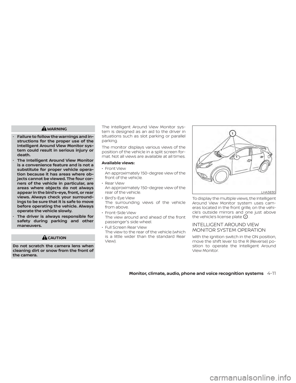
View). To display the multiple views, the Intelligent
Around View Monitor system uses cam-
eras located in the front grille, on the vehi-
cle’s outside mirrors and one just above
the vehicle’s license plate
O1.
INTELLIGENT AROUND VIEW
MONITOR SYSTEM OPERATION
With the ignition switch in the ON position,
move the shif t lever to the R (Reverse) po-
sition to operate the Intelligent Around
View Monitor.
LHA3830